| Issue |
A&A
Volume 630, October 2019
|
|
|---|---|---|
| Article Number | A133 | |
| Number of page(s) | 11 | |
| Section | The Sun | |
| DOI | https://doi.org/10.1051/0004-6361/201935126 | |
| Published online | 04 October 2019 | |
Using the infrared iron lines to probe solar subsurface convection
1
Max Planck Institute for Solar System Research, Justus-von-Liebig Weg 3, 37077 Göttingen, Germany
2
Department of Physics, University of Colorado, Boulder, CO 80309, USA
e-mail: This email address is being protected from spambots. You need JavaScript enabled to view it.
3
Laboratory for Atmospheric and Space Physics, University of Colorado, Boulder, CO 80303, USA
4
National Solar Observatory, Boulder, CO 80303, USA
Received:
25
January
2019
Accepted:
9
April
2019
Abstract
Context. Studying the properties of solar convection using high-resolution spectropolarimetry began in the early 1990s with the focus on observations in the visible wavelength regions. Its extension to the infrared (IR) remains largely unexplored.
Aims. The IR iron lines around 15 600 Å, most commonly known for their high magnetic sensitivity, also have a non-zero response to line-of-sight (LOS) velocity below log(τ) = 0.0. In this paper we explore the possibility of using these lines to measure subsurface convective velocities.
Methods. By assuming a snapshot of a three-dimensional magnetohydrodynamic simulation to represent the quiet Sun, we investigate how well the iron IR lines can reproduce the LOS velocity in the cube and to what depth. We use the recently developed spectropolarimetric inversion code SNAPI and discuss the optimal node placements for the retrieval of reliable results from these spectral lines.
Results. We find that the IR iron lines can measure the convective velocities down to log(τ) = 0.5, below the photosphere, not only at the original resolution of the cube, but also when degraded with a reasonable spectral and spatial PSF and stray light. Instead, the commonly used Fe I 6300 Å line pair performs significantly worse.
Conclusions. Our investigation reveals that the IR iron lines can probe the subsurface convection in the solar photosphere. This paper is a first step towards exploiting this diagnostic potential.
Key words: methods: data analysis / line: profiles / Sun: infrared
© I. Milić et al. 2019
 Open Access article, published by EDP Sciences, under the terms of the Creative Commons Attribution License (http://creativecommons.org/licenses/by/4.0), which permits unrestricted use, distribution, and reproduction in any medium, provided the original work is properly cited.
Open Access funding provided by Max Planck Society.
1. Introduction
Convective elements overshooting from below the solar surface manifest themselves as bright granules surrounded by dark intergranular lanes, a characteristic feature of the solar photosphere. Their properties, such as size, lifetime, brightness variation, and evolution, have been long studied and have helped to deepen our understanding of the energy and mass transport to the solar surface (Ruiz Cobo et al. 1996; Hirzberger et al. 1997; Berrilli et al. 1999; Borrero & Bellot Rubio 2002; Frutiger et al. 2000; Kiefer et al. 2000; Berrilli et al. 2002; Carbone et al. 2002; Koza et al. 2006; Kostik & Khomenko 2007; Oba et al. 2017a,b; Lemmerer et al. 2017). For a detailed review on solar convection see Nordlund et al. (2009).
The line-of-sight (LOS) component of the solar convective velocity can be estimated from the Doppler shift of spectral lines using methods such as bisector analysis, inversions applied to spectroscopic or spectropolarimetric data, and measuring the Doppler shift of the line core. Local correlation tracking and methods based on neural networks (Asensio Ramos et al. 2017) have been developed to measure the horizontal component. Measurements of the LOS velocity using ground- and space-based instruments show a general trend of decreasing upflow and downflow with increasing atmospheric height, consistent with overshooting convection. Over the years a range of values have been reported in the literature. For example, Berrilli et al. (1999), using THEMIS observations, measured the mean granular velocity to vary from −171 m s−1 to −93 m s−1 and in the cell boundaries from 57 m s−1 to 81 m s−1. Kiefer et al. (2000) measured 1–2 km s−1 rms velocity in the granules. Height stratified convective velocities using multi-line inversions employing multi-component model atmospheres can be found in Frutiger et al. (2000), Borrero & Bellot Rubio (2002), Koza et al. (2006). Recently, Oba et al. (2017a) measured amplitudes of upflow and downflow velocities ranging from −3.0 km s−1 to +3.0 km s−1, and compared them with numerical simulations.
Spectral lines in the visible range, Fe I 5576.1 Å, Fe II 5234 Å, the Fe I lines observed by Hinode Solar Optical Telescope at 6301 Å and 6302 Å, and Fe I 5250 Å to name a few, are commonly used for convective velocity measurements. These lines have a typical height of formation between 200 km and 400 km above the solar photosphere. Berrilli et al. (1999, 2002) used the C I 5380.3 Å line that probes lower heights (roughly 60 km above the photosphere) to study convection at the granules and the cell boundaries. However, probing the solar convection at infrared wavelengths has so far remained unexplored. The well-known Fe I lines in the infrared at 15 600 Å are known to have a low formation height (e.g., Borrero et al. 2016) and this property of the infrared lines has been exploited to probe deep into the solar photosphere, in the sunspot penumbrae, by Borrero et al. (2016), but also in the quiet Sun (Martínez González et al. 2007, 2008, 2016; Lagg et al. 2016; Kiess et al. 2018). Also, the mean solar spectrum of these lines was modeled, either to infer atomic parameters (Borrero et al. 2003) or to verify state-of-the-art magneto hydrodynamic (MHD) simulations (Beck et al. 2013). The authors most often discuss the ability of these lines to constrain the atmospheric parameters at log(τ5000) = 0.0. However, when we examine their response functions, the lines also sample layers below log(τ5000) = 0.0 (discussed in Sect. 2). Additionally, their high excitation potential make them less sensitive to temperature fluctuations. This leads us to the question of whether it is possible to extract reliable atmospheric parameters from layers below the photosphere, i.e., at log(τ5000) > 0. If yes, then what is an optimal setup required for the inversions? Exploring this is one of the main aims of the present paper, with a particular focus on the convective velocity.
We synthesize the Stokes profiles from a three-dimensional magneto hydrodynamic (3D MHD) cube representative of the quiet Sun atmosphere and perform state-of-the-art inversions using the newly developed Spectropolarimetric NLTE Analytically-Powered Inversion (SNAPI) code (Milić & van Noort 2017, 2018). By experimenting with the placement of nodes, we investigate the deepest layers in the solar atmosphere that we can reliably diagnose with the infrared lines of iron at 15 600 Å. We then repeat the process for the widely used iron line pair at 6300 Å, and discuss the differences in the retrieved velocities. The whole procedure is then repeated by degrading the data enough to resemble the observations from the new and upgraded version of the GREGOR Infrared Spectrograph (GRIS; Collados et al. 2012), which is called GRIS+. This study gives us an estimate on the extent of spatial detail we can hope to see from the inversion of this infrared spectral region using GRIS+. We present a detailed investigation with different levels of degradation. We compare the inverted atmosphere with the original MHD atmosphere, and this gives us an idea of the reliability of our diagnostics and helps us determine the optimal setup for the inversion of the actual telescope data.
Section 2 describes the details of the MHD cube and the Stokes profile synthesis. The inversion of synthetic data with different degrees of degradation is explained in Sect. 3, where the results from the infrared lines are compared with those from the Fe I 6300 Å line pair. Our conclusions are outlined in Sect. 4.
2. MHD cube and profile synthesis
For the purpose of this study, we consider a 3D MHD snapshot to be an example of a “true” solar atmosphere. We note that this very well might not be the case as we are currently not sure how well current simulations describe the Sun. That discussion, however, is beyond the scope of this paper. What matters to us is that the snapshot is probably a reasonable imitation of the real atmosphere as most of its observed properties can be reproduced (e.g., Danilovic et al. 2008). By synthesizing the spectra from the cube and applying instrumental effects to it, we aim to achieve data of similar quality to real observations. If we apply our diagnostics technique (inversion in this case) to this data, we obtain the physical properties of the atmosphere. There is one big difference with respect to the real observations, however: we know what the original atmosphere looks like, and we can compare the inferred atmosphere with the original one. Thus, we are able to test the reliability of our inversion. We focus on the following two aspects:
-
Retrieving information from deep layers: since the infrared lines of iron that we are interested in lie in the spectral region where the H− opacity reaches minimum, we expect the lines to be more sensitive to the deep layers (i.e., deeper than log τ = 0). By inverting synthetic data and comparing inferred and original atmospheres we can explicitly see up to what depth the two agree and thus conclude how deep we can probe by using this spectral window. Furthermore, we perform a direct comparison with the iron line pair at 6300 Å, i.e., we investigate which line pair recovers the original atmosphere to a higher degree.
-
Seeing effects: the images of the Sun we obtain from the ground-based telescopes are blurred because of the turbulence in the Earth’s atmosphere. This is in addition to the diffraction at the telescope aperture. Adaptive optics and state-of-the art image reconstruction techniques such as Multi-Object Multi-Frame Blind Deconvolution (MOMFBD; van Noort et al. 2005) eliminate this blurring by a certain amount; however, the images are still not infinitely sharp. This means that spatial structures still remain that cannot be retrieved. To analyze the influence of this effect on the inferred atmosphere, we convolve the synthetic data with a theoretical telescope point spread function (PSF), and then perform the inversion on this degraded, simulated spectropolarimetric dataset. Again, we compare the inverted and the original atmospheres to estimate the amount of information that is lost due to this degradation. We note that this process is not identical to simply smearing the original MHD datacube with the telescope’s PSF. This is true because the relationship between the parameters we want to infer and the observables (Stokes vector) is highly nonlinear.
This numerical experiment allows us to characterize the reliability of our inversion and estimate the amount of information we are able to retrieve. In addition, we can prepare an optimal setup for the inversion of these iron lines that are often used to observe a variety of solar targets at the GREGOR telescope (Schmidt et al. 2012) using GRIS (Collados et al. 2012), and are also well suited for the upcoming instruments and facilities like the GRIS+ at GREGOR, European Solar Telescope (EST, Collados et al. 2013a), and the Daniel K. Inouye Solar Telescope (DKIST, Elmore et al. 2014).
There is an additional caveat: here we assume that our synthesis procedure applied to the MHD simulation accurately depicts the way observed Stokes profiles are generated. There are a number of reasons why this might not be the case:
-
Possible departures for Fe I populations from LTE, for example due to radiative overionization. This effect is important for the temperature inference, but much less so for the velocity;
-
Presence of mixed atmospheres in the observed pixel (we address this in the Sect. 3.3);
-
Inaccuracies in the atomic parameters and/or background opacities;
-
Presence of systematics in the observed data (cross talk, fringes, etc.).
In the following, we assume that we can obtain atomic parameters and continuum opacities that are accurate enough, and that our data is properly calibrated, but it is important to note that in the applications to actual telescope data this might not be the case.
2.1. MHD cube description
The 3D MHD cube used here is a non-gray atmosphere simulated from the MURaM code (Vögler et al. 2005). The details of the numerical setup of this simulation are described in Riethmüller et al. (2014). The cube has a horizontal resolution of 20.83 km and spans 6 Mm. In the vertical direction, the cube extends 1.4 Mm with a resolution of 14 km. The cube was generated by introducing a uniform vertical magnetic field of Bz = 50 G into a hydrodynamic atmosphere. This cube is the same as the one used in Smitha & Solanki (2017). The maps of temperature, LOS velocity, and the magnetic field strength at log(τ5000) = 0 can be found in that paper.
2.2. Spectrum synthesis and post processing
The MHD cube is essentially a 3D array of temperature, gas pressure, magnetic field, and velocity vectors on a specified geometrical grid. These quantities, together with the atomic models, are fed into the SNAPI synthesis/inversion code to synthesize the Stokes spectra of five neutral iron lines in the spectral region between 15 640 and 15 670 Å, with 20 mÅ sampling. The details of the lines are given in Table 1. Their line strengths and Landé factors differ significantly, which offers an added advantage because spectral lines of different strength (opacity) probe different depths in the atmosphere, such that the full spectral window provides us with a larger vertical span compared to just one spectral line. Different magnetic sensitivity is crucial in decreasing degeneracy in the inferred parameters. Since these lines are formed quite deep in the atmosphere where collisions dominate, we assume local thermodynamic equilibrium (LTE), which accelerates the profile synthesis and the inversion. To calculate collisional broadening, we use the approach from Barklem & O’Mara (1997), and we provide the coefficients we used in the table.
Details of the infrared lines.
The next step is post-processing the data such that it resembles the real observations. We consider three main effects: spectral smearing in the spectrograph, spatial smearing due to the finite spatial resolution, and the presence of photon noise. Accordingly, we prepare three different versions of the dataset for the infrared lines:
-
Version 0 (v0): The original data without any instrumental effects;
-
Version 1 (v1): The original data, spectrally convolved with a Gaussian filter with full width at half maximum (FWHM) of 150 mÅ and then resampled to a spectral resolution of 60 mÅ. To this we added a wavelength independent Gaussian noise equal to 3 × 10⁻⁴ of the quiet Sun continuum intensity. This is the level of noise the GRIS+ instrument is expected to deliver when observing the quiet Sun;
-
Version 2 (v2): Same as version 1, except that we now also apply spatial smearing. We assume a Gaussian spatial PSF with FWHM of 0.26″ which corresponds approximately to 200 km on the solar surface or ten pixels in the original MHD simulation. In addition, we consider another component of PSF, which is also a Gaussian but much broader (FWHM = 2″), which mimics the so-called stray light. The stray light is a consequence of the broad wings of the PSF and is very hard to correct for using the MOMFBD or similar image restoration techniques. We assume different amounts of stray light (10%–30%), and refer to these versions as v2.1, v2.2, and v2.3. For inversion purposes, these data cubes have also been rebinned to 3 × 3 bins, which correspond to spatial sampling of 0.085″ in the plane of the sky.
An example of the v1 and v2 synthesized data is shown in Fig. 1. The loss of spatial detail after the convolution with a PSF 0.26″ in width is evident, although this would be a rather good resolution for a ground-based telescope so far in the infrared. Our goal now is to analyze this data, treating them like real observations.
 |
Fig. 1. Original (left) and convolved (right) synthetic images resulting from the MURaM cube. Upper panels show intensity in the continuum and lower panels the circular polarization in the wing of 15 662 Å line. |
3. Inversions
Spectropolarimetric inversion is the process of fitting a model atmosphere to the observed Stokes spectrum. The model atmosphere (or the corrections to it), are usually parametrized using nodes, pre-chosen points in depth, where the atmosphere is allowed to vary while the values in between the nodes are interpolated (usually using splines). This parametrization reduces the number of free parameters and keeps the inferred atmospheres relatively simple. Inversions allow us to infer the spatial distribution and height stratification of the temperature, LOS velocity, and magnetic field in the observed patch of the solar surface, making it one of the preferred tools for quantitative interpretation of spectropolarimetric data. For an excellent recent review on spectropolarimetric inversions, see del Toro Iniesta & Ruiz Cobo (2016).
In this section we present the inversions of the synthetic data described above. We again use SNAPI, which is an inversion code intended for NLTE lines, but can also be applied to lines formed in LTE conditions and provides increased flexibility in positioning of nodes for different parameters.
We chose an atmospheric model with five nodes in temperature, four nodes in the LOS velocity, and two in magnetic field strength with constant magnetic field inclination and microturbulent velocity. As our focus is mainly on velocity diagnostics, we chose to fit only the Stokes I and V profiles (also because the linear polarization still exhibits a relatively high level of noise). Adding information from Stokes V helps us determine the magnetic field strength, and thus avoid possible degeneracy between the magnetic field and velocity. The node positions are given in Table 2. We note that τ refers to the continuum optical depth at 5000 Å, so the deepest nodes are lying underneath what we usually refer to as the photosphere (log τ5000 = 0). We note that the optimal choice of nodes (their number and position) for the parametrization of the atmosphere is a matter of constant discussion in the spectropolarimetric community. While this has often been referred to as an art (del Toro Iniesta & Ruiz Cobo 2016), a detailed systematic investigation using model fitting is definitely lacking.
Node configuration used for the inversion of the synthetic data.
This particular node positioning was chosen to probe LOS velocities in the range −1.5 < log τ < 0.5. The uppermost velocity node (log τ = −2.5) sets the derivative of the velocity in the node at log τ = −1.5. The sensitivity of the chosen infrared lines to layers below log τ5000 can be seen from the response functions of Stokes I to the LOS velocity (Fig. 2). Response functions (Landi Degl’Innocenti & Landi Degl’Innocenti 1977; Ruiz Cobo & del Toro Iniesta 1994) are a measure of how the emergent spectrum responds to the perturbation of different physical quantities at different depths, and these particular ones are calculated from using the FALC (Fontenla et al. 1993) semi-empirical model atmosphere. Response functions provide information on the diagnostic potential of the lines in the selected wavelength region, and their calculation is necessary for the inversion procedure. From the figure, it is clear that radiation from the chosen spectral lines is sensitive to velocity perturbations from below the photosphere. Though the visible lines at 6300 Å also have a non-zero response for log τ > 0.0, the responses from the infrared lines seem to be somewhat stronger.
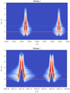 |
Fig. 2. Response functions of Stokes I to the LOS velocity, for the two reddest infrared iron lines (top), and for the iron pair at 6300 Å (bottom). Both response functions are normalized with respect to their maximum value. The blue line outlines the shape and the position of the spectral lines and the red line emphasizes the log τ5000 surface. |
It should be noted that we include microturbulent velocity in the model used for inversion, although the original MHD cube contains no such quantity. Microturbulent velocity was introduced in the early solar atmospheric modeling where it was used to explain the spectrum of the spatially unresolved Sun using 1D models. Originally, microturbulent velocity accounted for all the unresolved velocities, in all three coordinates. With today’s instruments, we can resolve velocities in the (x, y) plane (i.e., on the plane of the sky) rather well. Still, we use the microturbulent velocity in inversions in order to account for the complicated depth structure in velocity, which cannot be fully resolved by our simple, node-based model. Finally, we note that the term microturbulent is confusing as there is no consensus on the relationship between these ad hoc introduced velocities and turbulent processes in solar plasma.
As is commonly done, we eliminated gas pressure as a free parameter by using the assumption of hydrostatic equilibrium. To do this, one can either assume an upper boundary condition for the pressure, or make additional assumptions. The SNAPI code relies on the approach from Böhm-Vitense (1989), where the atmosphere is assumed to be exponentially stratified above the uppermost point, and then the pressure in that point is obtained by iteration.
The synthetic spectra are inverted using a multi-cycle approach for spatial regularization. In other words, after every ten fitting iterations we apply 2D median and Gaussian filters in the (x, y) plane, to each of the model parameters, which in the case of SNAPI are values in the pre-determined nodes in optical depth (for more details on the node approach, see, e.g., Milić & van Noort 2018; de la Cruz Rodríguez et al. 2019). This ensures the smoothness of the parameter maps and helps avoid local minima. The process is repeated until both average χ2 and the maximum χ2 in all the pixels do not change substantially (typically 6–7 cycles, or ≈100 iterations in total). After obtaining the converged solution, we take the following steps: (1) Compare the observed and fitted spectra to make sure that the agreement is satisfactory; (2) Compare the inferred and the original atmospheres and check if we are able to reliably retrieve velocities at the optical depths we are interested in.
3.1. Inversion of the data with no telescope PSF
As a first test of our inversion setup we first invert the original data, without any noise and with the original sampling (i.e., v0 data), and compare the original MHD atmosphere with the inverted atmosphere. From now on we only show the comparison between velocities. In the original cube we have the physical parameters on a (x, y, z) grid. Inversions, however, can only retrieve parameters on a (x, y, τ) grid, due to the nature of the radiative transfer process (from now on we use τ to denote continuum optical depth at 5000 Å). Therefore, we must change the z coordinate in the original MHD cube to τ. The SNAPI code does this automatically during the synthesis. We chose three different depths for comparison: log τ = 0.5 (deep photosphere), log τ = −0.5 (a layer where commonly used lines in the optical domains are sensitive to velocity), and log τ = −1.5 (upper photosphere). Figure 3 shows agreement between velocities in these three atmospheric depths. The velocity map in the upper layers (log τ = −1.5) is somewhat more noisy, while the velocities in the deep photosphere seem to show slightly higher values than the original ones. However, from the point of the velocity field distribution, agreement is generally excellent at each of the three depths, which shows that this spectral region carries enough information to reliably retrieve velocities at different depths, assuming the observations have very high spectral resolution and very low noise.
 |
Fig. 3. Comparison between LOS velocities in the MHD simulation and as returned by the inversion code, from the undegraded synthetic data, at three different depths in the atmosphere (log τ = −1.5, − 0.5, 0.5). In all the figures, the LOS velocities are indicated in km s−1. |
We then show the results from the inversion of synthesized spectra which has been convolved with spectrograph profile and with added photon noise, but without spatial convolution (i.e., v1 data) and qualitatively compare the original and the inferred atmospheres. As a first check, we assess the goodness of the fit to the synthetic data by comparing the observed and fitted Stokes I/Iqs and V/Iqs at the continuum and at the core of the two redmost spectral lines (Fig. 4). Here Iqs is the spatially averaged continuum intensity at 15 600 Å.
 |
Fig. 4. Observed (Cols. 1 and 3), and best fit (Cols. 2 and 4) images at wavelengths corresponding to the continuum (top), and the line centers of the two reddest IR spectral lines considered in this study. All five lines were inverted, but only the two reddest are shown. The inverted data is the version 1 data (convolved with spectra PSF and with noise added). Stokes V images correspond to wavelengths shifted by 100 mÅ to the red. |
The fit quality in the two Stokes parameters is very good, with the average reduced χ2 around 10. We note that we fit the synthetic observations of all five lines, but only show fits for two of them for the sake of brevity. The fits in the other three lines are equally good. When discussing this particular value of χ2, it should be kept in mind that in spectropolarimetric inversions we are working with simplified atmospheres (with parameters defined just at the nodes) and that a noise of 3 × 10⁻⁴ is quite low. In our case, we obtain an average agreement between the observed and fitted spectra of around 0.1%, which would be extremely satisfying when fitting actual data from a telescope. Here we neglect all the possible systematics in the data, as well as possible inadequacies of the model (e.g., inaccurate atomic parameters).
We show the comparison between the original and inferred velocity structure in Fig. 5. The agreement in the two lowest depths is still remarkably good and we can conclude that the velocity structure of the atmosphere is well reproduced. In the upper layers (log τ = −1.5), the maps are slightly more noisy. Our explanation is as follows: convolving and resampling the data in wavelength results in smearing out the sensitivity of the line cores, and fewer data points from the line cores are sampled. Since the line cores are the spectral regions that are the most sensitive to the upper atmosphere, the sensitivity decreases. Still, the topology of the velocity field is well retrieved and there are no systematic offsets.
 |
Fig. 5. Same as Fig. 3, but here the spectra used for inversion have been convolved in wavelength to account for finite spectral resolution, and photon noise has been added. |
In order to test the limits of the sensitivity of those lines, we inverted the whole cube again, adding a node in velocity at log τ = 1. In the semi-empiric FALC atmosphere model, this corresponds to an extra ≈30 km in depth. If the spectra are sensitive to these depths, we expect the velocities to be well constrained. However, Fig. 6 shows that this is not the case. Although the agreement at log τ = 0.5 is still very good, velocity maps at log τ = 1 show a great deal of “salt-and-pepper” noise and artifacts. This indicates that sensitivity there is significantly lower, and that it does not make sense to infer velocities so deep in the atmosphere. We note that this is not a consequence of simple degeneracy (also known as cross talk) between the values of velocity in the two lowest nodes as in that case we would expect both parameter maps to be noisy.
 |
Fig. 6. Same as Fig. 5, except with now also invert and compare the plasma velocity at log τ = 1, and we compare the atmospheres at the different optical depths, namely log τ = 0.5, 1. |
3.2. Comparison with Fe I 6300 Å line pair
The analysis above clearly illustrates the capability of this infrared spectral region to retrieve sub-photospheric (i.e., below log τ5000) velocities. However, to truly evaluate its advantages and disadvantages with respect to visible lines, we repeated the analysis with the Fe 6300 Å line pair. These two spectral lines are widely used for magnetic field and velocity diagnostics (see, e.g., Lites et al. 1993; Westendorp Plaza et al. 1997, 2001, but also numerous recent works using data from Hinode SOT/SP instrument).
The data preparation and degradation process is identical, except that we calculate the spectrum with 10 mÅ sampling, and then convolve it with 20 mÅ FWHM Gaussian spectral PSF. Continuum intensity at 6300 Å is around 7 times higher than in the previously discussed infrared region, but the spectral sampling is 6 times more dense. This means that the number of photons arriving into our hypothetical detector per spectral bin is approximately the same, assuming the same spatial sampling and transmission. Hence, we degraded the data with the same relative photon noise as in the example above.
To make the comparison as straightforward as possible, we decided to fit the Fe 6300 Å data with the same node configuration as the infrared data (see Table 2 for the exact node configuration). Since there were many more nodes than normally used to invert Hinode data (e.g., Danilovic et al. 2016), we took special care to ensure that our retrieved atmospheres were smooth by employing a multicycle approach. We started with a smaller number of nodes and then worked up toward the more complicated models (e.g., as done in the SIR code by Ruiz Cobo & del Toro Iniesta 1992). We were thus able to compare which of the two synthetic datasets (infrared or the visible) constrains the model better. We focused on the velocity retrieval. Figure 7 shows the original and inferred velocities at the same three optical depths as in the previous example. In the upper layers (log τ = −1.5) the agreement looks slightly better than in the case of infrared lines. In the middle layers the agreement is equally good. However, in the deep layers there is large overshoot of the intergranular velocities. Our interpretation is that, because of the low sensitivity of the lines to deep velocities, the inversion code overestimates the magnitude in order to get correct derivative of the velocity in the upper layers, while misdiagnosing the actual velocity values at log τ = 0.5. The better performance of the infrared lines in the deeper layers can also be seen from the scatter plots between the original and the inferred values in Figs. 5 and 7.
While plotting the distributions of the velocities gives us an insight into diagnostic potential, it is beneficial to come up with a quantitative measure of the agreement and compare it between different sets of lines. The simplest way is to compare the standard deviation of the absolute difference between the LOS velocities in original and inferred atmospheres at several depths. We present this plot in Fig. 8. We also plot the Pearson’s correlation coefficients between the original and inferred velocities at multiple optical depths. Both quantities confirm what we see in the images: infrared lines retrieve better subphotospheric velocities, while in the upper layers the two sets of lines give similar results. We note that the standard deviation and the correlation coefficients are subject to noise (which increases scatter) and the node configuration (which can systematically change agreement between original and inferred atmospheres). However, these results confirm the prevailing understanding that the infrared iron lines are, in general, better at probing deeper layers of the atmosphere. We did not test the agreement in the even higher layers thoroughly, but we note that at log τ = −2 the reliability of infrared lines suddenly drops. This is similar to what happens with visible lines at log τ = 0.5. This suggests that the sensitivity of spectral lines to velocity is confined to a well-defined range of optical depths.
 |
Fig. 8. Top: Pearson’s correlation coefficient between the velocities in the original MHD cube, and the velocities inferred by spectropolarimetric inversion from the two sets of lines (the value closer to unity is better). Bottom: standard deviation of the absolute difference between the original and the inferred velocities (lower values are better). |
3.3. Inversion of the spatially smeared data
In the previous subsections we discussed the retrieval of the original atmosphere under the implicit assumption that we are able to resolve it spatially. However, we are almost sure that with today’s resolving power the part of the solar atmosphere that fits into a resolution element is not homogeneous in the (x, y)-plane, i.e., we are observing a mixture of 1D atmospheres. We have already illustrated its effect on the observables in Fig. 4.
Now we discuss the atmosphere obtained by inverting synthesized spectra that have been subsequently spatially smeared using a Gaussian filter with FWHM equal to 0.26″, corresponding to the diffraction limit for the GREGOR telescope at 15 600 Å. Under good seeing conditions, and after the application of the spectral restoration technique van Noort (2017), we can realistically expect to achieve a spatial resolution close to this value. Inversion of the data convolved with the telescope PSF will result in a 3D atmosphere. We note that this atmosphere is not identical to the original atmosphere convolved with the PSF, because spectral synthesis and PSF application do not commute; in other words, the atmosphere that explains PSF-smeared observations is not the same as the PSF-smeared original atmosphere.
Before discussing the results we note that there is an another effect that will spatially couple the neighboring atmospheres: multidimensional radiative transfer in the presence of scattering. These effects can be safely neglected for the lines we are considering, but they become very important for scattering dominated lines formed in the upper photosphere and the chromosphere.
The fit of the convolved profiles is again excellent, although the inferred atmospheres show a significant loss of spatial detail, as expected. While the topology and the velocities are rather well recovered in the middle and lower layers, the discrepancy at log τ5000 = −1.5 is large. Notably, the surface area covered by downflows is much smaller and it also seems that the downflow intensity is lower (left panel of Fig. 9).
 |
Fig. 9. Comparison between the inferred velocities at three optical depths for the data smeared only with narrow PSF (left), and with added stray light (right). |
It is not obvious how to statistically compare the simulated and inverted atmospheres in this case. We prefer not to convolve the original atmosphere with PSF since, as we have already stressed, PSF can only operate on the observables. For the moment we conclude that the velocities around log τ = −0.5 and log τ = 0.5 are well recovered, despite the loss of resolution, and that the eventual use of telescopes with larger apertures will allow us to resolve finer structures of the velocity field (see next Sect. 3.4 for a more quantitative analysis).
3.4. Influence of stray light
In addition to the relatively narrow and arguably well understood PSF of the telescope, which is in large part compensated for by using adaptive optics and restoration techniques, solar images often suffer from non-negligible stray light. This stray light can be understood as a relatively spatially flat, wavelength dependent background added to the spectral cube. Its origin is probably in the very wide wings of the PSF that the adaptive optics and image reconstruction cannot compensate for. In our study we modeled it as an additional, broader Gaussian (FWHM = 5″). So, when accounting for stray light we generated our simulated images as
 (1)
(1)
Here G(σ) denotes a Gaussian with FWHM equal to σ, k is the amount of stray light that we vary from 0 to 30%,  , and σ2 = 2″. The operator ⊛ represents convolution. In the first approximation, in the observations of the quiet Sun, the stray light adds an amount of mean quiet Sun spectrum to each individual pixel, thus lowering the contrast, broadening the lines, and decreasing the sensitivity of the spectrum to the velocity fields.
Some inversion codes use stray light as a free parameter in the inversion procedure. In our opinion, stray light should be consistently applied to all the pixels either by inferring it separately before the inversion or by simultaneously inverting the whole field of view (similarly to, e.g., van Noort 2012). In this work we do not employ any of these, specifically because we want to see how the unknown stray light influences the inferred atmospheres.
Qualitatively, the presence of stray light in these amounts does not fundamentally change the inferred velocities, and the inferred velocity maps (Fig. 9) exhibit the same properties as discussed in Sect. 3.3. As a way of quantitatively analyzing the data, we show the distributions of the absolute values of the LOS velocities at these three atmospheric depths, for the original MHD atmosphere, the inversion of the spatially smeared data, and the inversion of spatially smeared data with the PSF. The distributions are given in Fig. 10. It seems like the presence of the stray light does not significantly change the inferred velocity distributions. The biggest difference is in the deepest layers, which makes sense because velocities there leave imprints in the far wings of the spectral lines where the intensity contrast is the lowest, and is thus affected the most by the presence of the stray light.
 |
Fig. 10. Histograms of the absolute values of LOS velocities in the original atmosphere and as inferred from the inversion of PSF-smeared data, without and with the additional stray light. |
4. Conclusions
In this paper we studied the diagnostic potential of the five infrared iron lines around 15 000 Å. The main premise is, because of the low continuum opacity around these wavelengths, that we should be able to probe atmospheric parameters in deeper layers in comparison to the commonly used lines in the optical domain (e.g., Fe 6300 Å line pair). In this particular study we focused on the LOS velocities as they are of great interest in the study of the behavior of convection at different atmospheric depths.
To this end, we synthesized polarized spectra of the five considered spectral lines (Table 1), using a state-of-the-art MuRAM radiative magnetohydrodynamic simulation of the quiet solar atmosphere as the input. We then degraded the synthesized spectra by adding spectral PSF, photon noise, and the spatial two-component PSF. In this way we tried to mimic the telescope data, which was subsequently inverted (i.e., we tried to infer the atmospheric parameters in the input MHD cube). We then directly compared the inferred and original velocities at three iso-optical depth surfaces (log τ = −1.5, − 0.5, 0.5). Our analysis indicates the following:
-
Inversion of the “original” (i.e., undegraded) spectra, retrieves original velocities very well;
-
Spectrally smearing the data assuming modest spectral resolution of 105 and adding a small amount of photon noise of 3 × 10⁻⁴ in the units of continuum intensity does not change results significantly;
-
The agreement breaks at log τ = 1, although the topology of the velocity field is roughly retrieved;
-
Repeating the same experiment using 6300 Å lines of iron shows that optical lines are much less sensitive to the deeper layers, though they have a non-zero response function at these layers. Specifically, the intergranular velocities at deeper layers (log τ = 0.5) are significantly overestimated. In the layers where −1.5 < log τ < 0, in the absence of spatial PSF, both spectral regions show excellent diagnostic potential;
-
Inversion of spatially smeared and binned data leads to the expected loss of spatial detail, but it also seems that the velocities in the upper layers are severely misdiagnosed: granular velocities seem to be higher than the original ones, while the area covered by downflows seems to be smaller;
-
Adding another wide component to the PSF that mimics the stray light in the amount of 30% does not change the inferred velocities significantly. This is evident from Figs. 9 and 10.
We hope that this investigation emphasizes the strengths of this spectral region in spectropolarimetric inversions. Estimating velocity (and the magnetic field) deep in the photosphere, combined with the chromospheric diagnostics paints a complete picture of the solar atmosphere and allows us to better characterize important phenomena (e.g., energy transport, reconnection). Also, there might be phenomena happening only in the deep layers that we will not be able to detect using other diagnostics. Finally, with the advent of next generation solar telescopes (e.g., DKIST and EST Elmore et al. 2014; Collados et al. 2013b), it will be of crucial importance to use spectral regions outside of visible, and we argue that this is one of the most useful ones for photospheric diagnostics.
Acknowledgments
We thank T. Riethmüller for kindly providing the MHD cube used in this paper. This project has received funding from the European Research Council (ERC) under the European Union’s Horizon 2020 research and innovation program (grant agreement No. 695075). This research has made use of NASA’s Astrophysics Data System.
References
- Asensio Ramos, A., Requerey, I. S., & Vitas, N. 2017, A&A, 604, A11 [NASA ADS] [CrossRef] [EDP Sciences] [Google Scholar]
- Barklem, P. S., & O’Mara, B. J. 1997, MNRAS, 290, 102 [Google Scholar]
- Beck, C., Fabbian, D., Moreno-Insertis, F., Puschmann, K. G., & Rezaei, R. 2013, A&A, 557, A109 [NASA ADS] [CrossRef] [EDP Sciences] [Google Scholar]
- Berrilli, F., Florio, A., Consolini, G., et al. 1999, A&A, 344, L29 [NASA ADS] [Google Scholar]
- Berrilli, F., Consolini, G., Pietropaolo, E., et al. 2002, A&A, 381, 253 [NASA ADS] [CrossRef] [EDP Sciences] [Google Scholar]
- Böhm-Vitense, E. 1989, Introduction to Stellar Astrophysics. Vol. 2. Stellar Atmospheres (Cambridge: Cambridge University Press) [Google Scholar]
- Borrero, J. M., & Bellot Rubio, L. R. 2002, A&A, 385, 1056 [NASA ADS] [CrossRef] [EDP Sciences] [Google Scholar]
- Borrero, J. M., Bellot Rubio, L. R., Barklem, P. S., & del Toro Iniesta, J. C. 2003, A&A, 404, 749 [NASA ADS] [CrossRef] [EDP Sciences] [Google Scholar]
- Borrero, J. M., Asensio Ramos, A., Collados, M., et al. 2016, A&A, 596, A2 [NASA ADS] [CrossRef] [EDP Sciences] [Google Scholar]
- Carbone, V., Lepreti, F., Primavera, L., et al. 2002, A&A, 381, 265 [NASA ADS] [CrossRef] [EDP Sciences] [Google Scholar]
- Collados, M., López, R., Páez, E., et al. 2012, Astron. Nachr., 333, 872 [NASA ADS] [CrossRef] [Google Scholar]
- Collados, M., Bettonvil, F., Cavaller, L., et al. 2013a, in Highlights of Spanish Astrophysics VII, eds. J. C. Guirado, L. M. Lara, V. Quilis, & J. Gorgas, 808 [Google Scholar]
- Collados, M., Bettonvil, F., Cavaller, L., et al. 2013b, Mem. Soc. Astron. It., 84, 379 [NASA ADS] [Google Scholar]
- Danilovic, S., Gandorfer, A., Lagg, A., et al. 2008, A&A, 484, L17 [NASA ADS] [CrossRef] [EDP Sciences] [Google Scholar]
- Danilovic, S., van Noort, M., & Rempel, M. 2016, A&A, 593, A93 [NASA ADS] [CrossRef] [EDP Sciences] [Google Scholar]
- de la Cruz Rodríguez, J., Leenaarts, J., Danilovic, S., & Uitenbroek, H. 2019, A&A, 623, A74 [NASA ADS] [CrossRef] [EDP Sciences] [Google Scholar]
- del Toro Iniesta, J. C., & Ruiz Cobo, B. 2016, Liv. Rev. Sol. Phys., 13, 4 [Google Scholar]
- Elmore, D. F., Rimmele, T., Casini, R., et al. 2014, in Ground-based and Airborne Instrumentation for Astronomy V, Proc. SPIE, 9147, 914707 [Google Scholar]
- Fontenla, J. M., Avrett, E. H., & Loeser, R. 1993, ApJ, 406, 319 [NASA ADS] [CrossRef] [Google Scholar]
- Frutiger, C., Solanki, S. K., Fligge, M., & Bruls, J. H. M. J. 2000, A&A, 358, 1109 [NASA ADS] [Google Scholar]
- Hirzberger, J., Vázquez, M., Bonet, J. A., Hanslmeier, A., & Sobotka, M. 1997, ApJ, 480, 406 [NASA ADS] [CrossRef] [Google Scholar]
- Kiefer, M., Stix, M., & Balthasar, H. 2000, A&A, 359, 1175 [NASA ADS] [Google Scholar]
- Kiess, C., Borrero, J. M., & Schmidt, W. 2018, A&A, 616, A109 [NASA ADS] [CrossRef] [EDP Sciences] [Google Scholar]
- Kostik, R. I., & Khomenko, E. V. 2007, A&A, 476, 341 [NASA ADS] [CrossRef] [EDP Sciences] [Google Scholar]
- Koza, J., Kučera, A., Rybák, J., & Wöhl, H. 2006, A&A, 458, 941 [NASA ADS] [CrossRef] [EDP Sciences] [Google Scholar]
- Lagg, A., Solanki, S. K., Doerr, H.-P., et al. 2016, A&A, 596, A6 [NASA ADS] [CrossRef] [EDP Sciences] [Google Scholar]
- Landi Degl’Innocenti, E., & Landi Degl’Innocenti, M. 1977, A&A, 56, 111 [NASA ADS] [Google Scholar]
- Lemmerer, B., Hanslmeier, A., Muthsam, H., & Piantschitsch, I. 2017, A&A, 598, A126 [NASA ADS] [CrossRef] [EDP Sciences] [Google Scholar]
- Lites, B. W., Elmore, D. F., Seagraves, P., & Skumanich, A. P. 1993, ApJ, 418, 928 [NASA ADS] [CrossRef] [Google Scholar]
- Martínez González, M. J., Collados, M., Ruiz Cobo, B., & Solanki, S. K. 2007, A&A, 469, L39 [NASA ADS] [CrossRef] [EDP Sciences] [Google Scholar]
- Martínez González, M. J., Collados, M., Ruiz Cobo, B., & Beck, C. 2008, A&A, 477, 953 [NASA ADS] [CrossRef] [EDP Sciences] [Google Scholar]
- Martínez González, M. J., Pastor Yabar, A., Lagg, A., et al. 2016, A&A, 596, A5 [NASA ADS] [CrossRef] [EDP Sciences] [Google Scholar]
- Milić, I., & van Noort, M. 2017, A&A, 601, A100 [NASA ADS] [CrossRef] [EDP Sciences] [Google Scholar]
- Milić, I., & van Noort, M. 2018, A&A, 617, A24 [NASA ADS] [CrossRef] [EDP Sciences] [Google Scholar]
- Nordlund, Å., Stein, R. F., & Asplund, M. 2009, Liv. Rev. Sol. Phys., 6, 2 [Google Scholar]
- Oba, T., Iida, Y., & Shimizu, T. 2017a, ApJ, 836, 40 [NASA ADS] [CrossRef] [Google Scholar]
- Oba, T., Riethmüller, T. L., Solanki, S. K., et al. 2017b, ApJ, 849, 7 [NASA ADS] [CrossRef] [Google Scholar]
- Riethmüller, T. L., Solanki, S. K., Berdyugina, S. V., et al. 2014, A&A, 568, A13 [NASA ADS] [CrossRef] [EDP Sciences] [Google Scholar]
- Ruiz Cobo, B., & del Toro Iniesta, J. C. 1992, ApJ, 398, 375 [NASA ADS] [CrossRef] [Google Scholar]
- Ruiz Cobo, B., & del Toro Iniesta, J. C. 1994, A&A, 283, 129 [NASA ADS] [Google Scholar]
- Ruiz Cobo, B., del Toro Iniesta, J. C., Rodriguez Hidalgo, I., Collados, M., & Sanchez Almeida, J. 1996, in Cool Stars, Stellar Systems, and the Sun, eds. R. Pallavicini, & A. K. Dupree, ASP Conf. Ser., 109, 155 [NASA ADS] [Google Scholar]
- Schmidt, W., von der Lühe, O., Volkmer, R., et al. 2012, Astron. Nachr., 333, 796 [NASA ADS] [CrossRef] [Google Scholar]
- Smitha, H. N., & Solanki, S. K. 2017, A&A, 608, A111 [NASA ADS] [CrossRef] [EDP Sciences] [Google Scholar]
- van Noort, M. 2012, A&A, 548, A5 [NASA ADS] [CrossRef] [EDP Sciences] [Google Scholar]
- van Noort, M. 2017, A&A, 608, A76 [NASA ADS] [CrossRef] [EDP Sciences] [Google Scholar]
- van Noort, M., Rouppe van der Voort, L., & Löfdahl, M. G. 2005, Sol. Phys., 228, 191 [NASA ADS] [CrossRef] [Google Scholar]
- Vögler, A., Shelyag, S., Schüssler, M., et al. 2005, A&A, 429, 335 [NASA ADS] [CrossRef] [EDP Sciences] [Google Scholar]
- Westendorp Plaza, C., del Toro Iniesta, J. C., Ruiz Cobo, B., et al. 1997, Nature, 389, 47 [NASA ADS] [CrossRef] [Google Scholar]
- Westendorp Plaza, C., del Toro Iniesta, J. C., Ruiz Cobo, B., et al. 2001, ApJ, 547, 1130 [NASA ADS] [CrossRef] [Google Scholar]
Appendix A: Examples of fits and inferred profiles
An interesting aspect of this paper is the question of how well we can fit the synthetic spectra from the MHD model atmospheres that have complicated stratifications. On the other hand, the model we use is based on a fixed number of nodes, which means that we are, inevitably, simplifying the model atmospheres. Since the noise we use in this numerical experiment is very low (3 × 10⁻⁴), it is not a big surprise that we fail to obtain optimal fits. A simple criterion for an optimal fit in this case could be  , where
  is the reduced chi-squared.
We show in Fig. A.1 two representative fits, and the inferred and the original atmospheres. Qualitatively speaking, Stokes I fits are excellent as the continuum level, line depth, and line shape are completely reproduced. Stokes V fits are not as good, but mostly because the magnitude of the Stokes V is very small (the magnetic field is rather weak). It can be seen that temperature, gas pressure, and the velocity are well reproduced, while the magnetic field stratification seems to be too complicated to be picked up with our simple, two-node model.
 |
Fig. A.1. Top row (four panels): synthetic spectra and the best fits using node-based atmosphere model. Bottom rows (eight panels): inferred and original model atmospheres. Left: pixels with no polarization signal. Right: pixels with a weak polarization signal. |
However, the spatial distribution of the magnetic field seems to be well recovered (see Fig. A.2). Qualitatively, the magnetic fields agree with the original ones, but because they are generally weak there are many pixels where the discrepancy is large. We wanted to show these additional plots to demonstrate that our inversion scheme, although relatively simple, yields good fits and reproduces well the original MHD cube. To recover very complicated depth stratifications, we might have to turn to more sophisticated methods, such as regularization methods as suggested by de la Cruz Rodríguez et al. (2019), among others. We note that there is a fundamental limit in height resolution, dictated by the radiative transfer processes that sets the limit on how fine a vertical structure we can recover.
 |
Fig. A.2. Comparison between LOS magnetic fields in the MHD simulation and as returned by the inversion code, from the spectrally degraded synthetic data, at three different depths in the atmosphere (log τ = −1.5, − 0.5, 0.5). In all the figures, the magnetic field is in gauss. |
In this manuscript we chose to focus on convective LOS velocities, but a similar study is in place regarding the magnetic fields, especially in the age of new solar telescopes that should provide us with a leap in spatial resolution and polarimetric sensitivity.
All Tables
All Figures
|
Fig. 1. Original (left) and convolved (right) synthetic images resulting from the MURaM cube. Upper panels show intensity in the continuum and lower panels the circular polarization in the wing of 15 662 Å line. |
| In the text | |
|
Fig. 2. Response functions of Stokes I to the LOS velocity, for the two reddest infrared iron lines (top), and for the iron pair at 6300 Å (bottom). Both response functions are normalized with respect to their maximum value. The blue line outlines the shape and the position of the spectral lines and the red line emphasizes the log τ5000 surface. |
| In the text | |
|
Fig. 3. Comparison between LOS velocities in the MHD simulation and as returned by the inversion code, from the undegraded synthetic data, at three different depths in the atmosphere (log τ = −1.5, − 0.5, 0.5). In all the figures, the LOS velocities are indicated in km s−1. |
| In the text | |
|
Fig. 4. Observed (Cols. 1 and 3), and best fit (Cols. 2 and 4) images at wavelengths corresponding to the continuum (top), and the line centers of the two reddest IR spectral lines considered in this study. All five lines were inverted, but only the two reddest are shown. The inverted data is the version 1 data (convolved with spectra PSF and with noise added). Stokes V images correspond to wavelengths shifted by 100 mÅ to the red. |
| In the text | |
|
Fig. 5. Same as Fig. 3, but here the spectra used for inversion have been convolved in wavelength to account for finite spectral resolution, and photon noise has been added. |
| In the text | |
|
Fig. 6. Same as Fig. 5, except with now also invert and compare the plasma velocity at log τ = 1, and we compare the atmospheres at the different optical depths, namely log τ = 0.5, 1. |
| In the text | |
 |
Fig. 7. Same as Fig. 5, but using the Fe 6300 Å line pair. |
| In the text | |
|
Fig. 8. Top: Pearson’s correlation coefficient between the velocities in the original MHD cube, and the velocities inferred by spectropolarimetric inversion from the two sets of lines (the value closer to unity is better). Bottom: standard deviation of the absolute difference between the original and the inferred velocities (lower values are better). |
| In the text | |
|
Fig. 9. Comparison between the inferred velocities at three optical depths for the data smeared only with narrow PSF (left), and with added stray light (right). |
| In the text | |
|
Fig. 10. Histograms of the absolute values of LOS velocities in the original atmosphere and as inferred from the inversion of PSF-smeared data, without and with the additional stray light. |
| In the text | |
|
Fig. A.1. Top row (four panels): synthetic spectra and the best fits using node-based atmosphere model. Bottom rows (eight panels): inferred and original model atmospheres. Left: pixels with no polarization signal. Right: pixels with a weak polarization signal. |
| In the text | |
|
Fig. A.2. Comparison between LOS magnetic fields in the MHD simulation and as returned by the inversion code, from the spectrally degraded synthetic data, at three different depths in the atmosphere (log τ = −1.5, − 0.5, 0.5). In all the figures, the magnetic field is in gauss. |
| In the text | |
Current usage metrics show cumulative count of Article Views (full-text article views including HTML views, PDF and ePub downloads, according to the available data) and Abstracts Views on Vision4Press platform.
Data correspond to usage on the plateform after 2015. The current usage metrics is available 48-96 hours after online publication and is updated daily on week days.
Initial download of the metrics may take a while.