Fig. 2
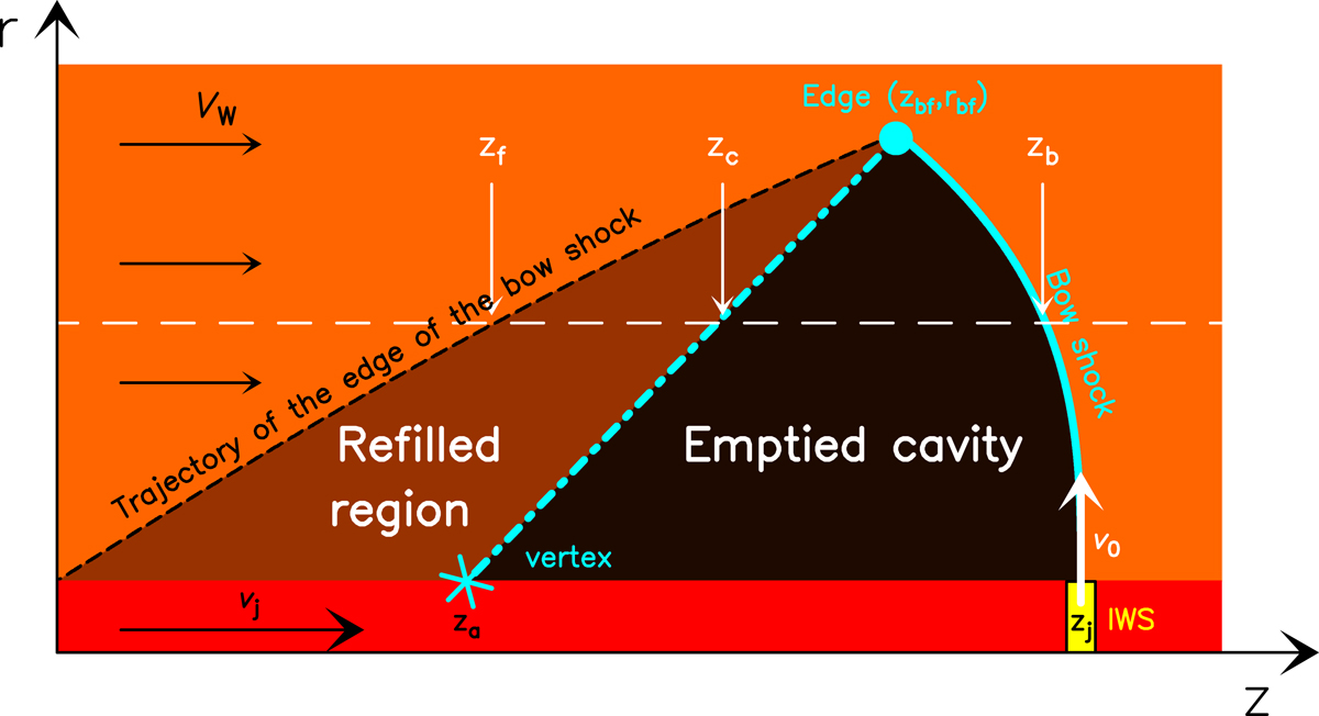
Schematic diagram showing the flow around a working surface of a jet (in this case the leading working surface, but the diagram also applies for an internal working surface). The jet is the horizontal, red rectangle at the bottom of the graph, with the source located at z = 0. The working surface in yellow is located at a distance zj from the source and travels at a velocity vj. It ejects material away from the axis at an initial velocity v0. The jet is surrounded by a “disk wind”, which travels along the outflow axis at a velocity vw. The shape of the thin-shell bow shock (thick cyan line) is given by zb as a function of r and ends at the edge of the bow wing (cyan point; zb f, rb f). The bow shock leaves behind a “cavity” (black region), which is partially refilled by the disk wind (brown region). The boundaries of the initial swept up cavity (in black dashed line) and of the refilled region (cyan dash-dotted line) are given by zf an zc (respectively) as a function of cylindrical radius r (see Eqs. (14) and (15)).
Current usage metrics show cumulative count of Article Views (full-text article views including HTML views, PDF and ePub downloads, according to the available data) and Abstracts Views on Vision4Press platform.
Data correspond to usage on the plateform after 2015. The current usage metrics is available 48-96 hours after online publication and is updated daily on week days.
Initial download of the metrics may take a while.