Fig. 1
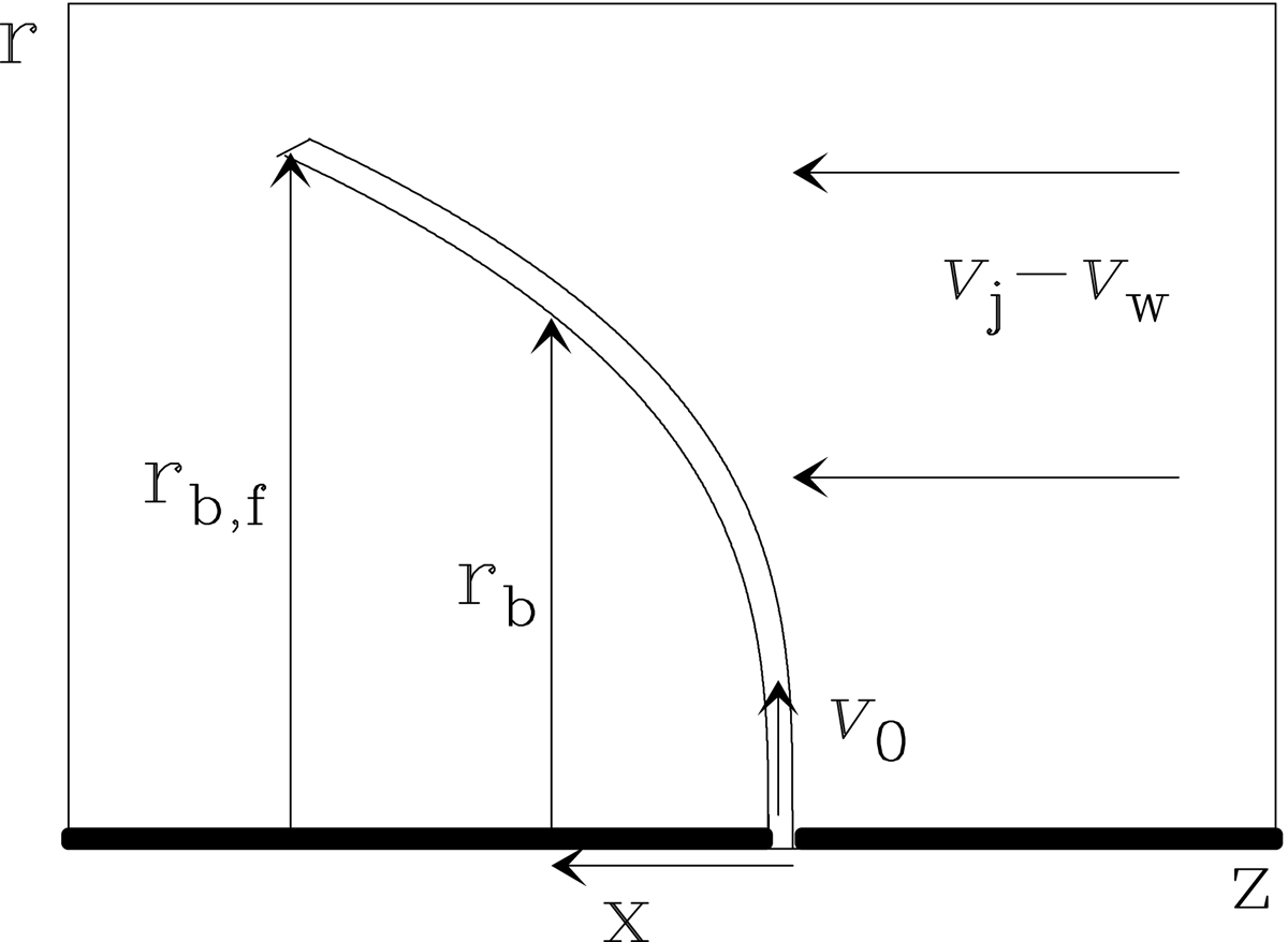
Schematic diagram of the flow around an internal working surface (IWS) in the frame of reference co-moving with the IWS at velocity vz = vj (a similar configuration would apply for the leading working surface of a jet). The thick, horizontal line at the bottom of the graph is the jet (with a gap showing the position of the IWS). The working surface ejects jet material sideways at an initial velocity v0 into the slower disk wind, which in this frame of reference moves towards the outflow source at velocity vj – vw. The distance x is measured towards the outflow source.The shape of the thin shell bow shock is given by rb(x) (see Eq. (5)), and terminates at the cylindrical radius rb; f(t) with t the time elapsed since formation of the IWS (see Eq. (8)).
Current usage metrics show cumulative count of Article Views (full-text article views including HTML views, PDF and ePub downloads, according to the available data) and Abstracts Views on Vision4Press platform.
Data correspond to usage on the plateform after 2015. The current usage metrics is available 48-96 hours after online publication and is updated daily on week days.
Initial download of the metrics may take a while.