Fig. 1
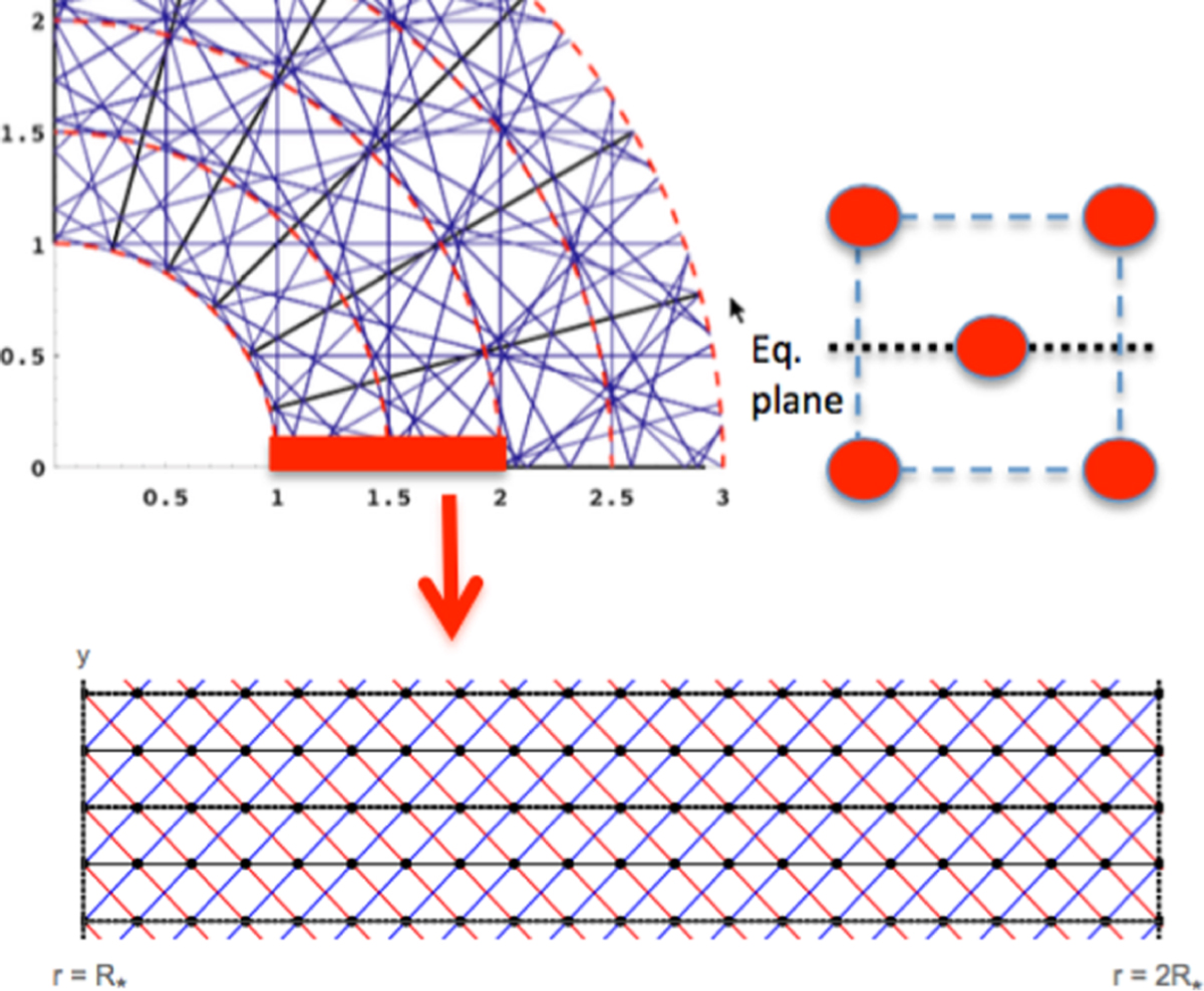
Sketch illustrating the basic idea of the pseudo-planar, box-in-a-wind approach used in this paper. The upper left illustrates the general situation of non-alignment between oblique rays and the numerical grid points. The lower panel then shows how we create a pseudo-planar box in the wind by cutting out a small but representative fraction of the wind volume. For illustration purposes, it shows projections onto the equatorial plane of rays in the prograde (blue), retrograde (red), and radial (black) directions for two lateral periods of a simple case with just ny = 2 zones in lateral direction y. The right panel then illustrates how extension out of the equatorial plane involves a total of five rays: one radial plus two oblique pairs that extend up/down from the plane. See Appendix A for a detailed explanation and for further illustrations of the assumed ray geometry.
Current usage metrics show cumulative count of Article Views (full-text article views including HTML views, PDF and ePub downloads, according to the available data) and Abstracts Views on Vision4Press platform.
Data correspond to usage on the plateform after 2015. The current usage metrics is available 48-96 hours after online publication and is updated daily on week days.
Initial download of the metrics may take a while.