| Issue |
A&A
Volume 607, November 2017
|
|
|---|---|---|
| Article Number | A6 | |
| Number of page(s) | 16 | |
| Section | Planets and planetary systems | |
| DOI | https://doi.org/10.1051/0004-6361/201630328 | |
| Published online | 30 October 2017 | |
A new method of correcting radial velocity time series for inhomogeneous convection
Univ. Grenoble Alpes, CNRS IPAG, 38000 Grenoble, France
e-mail: This email address is being protected from spambots. You need JavaScript enabled to view it.
Received: 22 December 2016
Accepted: 18 July 2017
Abstract
Context. Magnetic activity strongly impacts stellar radial velocities (RVs) and therefore the search for small planets. We showed previously that in the solar case it induces RV variations with an amplitude over the cycle on the order of 8 m/s, with signals on both short and long timescales. The major component is the inhibition of the convective blueshift due to plages.
Aims. In this paper we explore a new approach used to correct for this major component of stellar radial velocities in the case of solar-type stars.
Methods. The convective blueshift depends on line depths; we use this property to develop a method that will characterize the amplitude of this effect and to correct for this RV component. We build realistic RV time series corresponding to RVs computed using different sets of lines, including lines in different depth ranges. We characterize the performance of the method used to reconstruct the signal without the convective component and the detection limits derived from the residuals.
Results. We identified a set of lines which, combined with a global set of lines, allows us to reconstruct the convective component with a good precision and to correct for it. For the full temporal sampling, the power in the range 100−500 d significantly decreased, by a factor of 100 for a RV noise below 30 cm/s. We also studied the impact of noise contributions other than the photon noise, which lead to uncertainties on the RV computation, as well as the impact of the temporal sampling. We found that these other sources of noise do not greatly alter the quality of the correction, although they need a better noise level to reach a similar performance level.
Conclusions. A very good correction of the convective component can be achieved providing very good RV noise levels combined with a very good instrumental stability and realistic granulation noise. Under the conditions considered in this paper, detection limits at 480 d lower than 1 MEarth could be achieved for RV noise below 15 cm/s.
Key words: techniques: radial velocities / planetary systems / Sun: activity / Sun: faculae, plages / sunspots
© ESO, 2017
1. Introduction
Stellar variability at various timescales strongly affects the ability to detect exoplanets. The magnetic activity contribution to radial velocities (RVs) is due to the following components (Meunier et al. 2010): the photometric contribution of spots, plages, and network (hereafter RVsppl), which depends on their intensity contrast and size, and the attenuation of the convective blueshift in plages (hereafter RVconv), which depends on the attenuation of the convective blueshift and plage size. In the case of the Sun, the latter is expected to dominate the signal, as shown in Fig. 1. Attempts to correct for the RVconv signal have been made using different techniques: correlation with chromospheric emission (Meunier & Lagrange 2013), which provides correction on both long (cycle) timescales and short (rotational) timescales, or correlation with a smoothed chromospheric emission (Dumusque et al. 2012) to remove some contribution on long timescales; harmonic fittings or fits using a limited number of structures to remove some stellar signals at the rotational period (e.g., Boisse et al. 2011; Dumusque et al. 2012, 2014); use of photometric times series to estimate the RV signal (Aigrain et al. 2012).
On the other hand, it has been shown that the amount of convective blueshift, when the spectral line positions are computed using the bottom of lines, i.e., the lower part of the line around the line center, and eliminating the contribution of the wings depends on the depths of the spectral lines used to compute the RV (Dravins et al. 1981), controlling directly the RVconv amplitude, while RVsppl does not depend on these line depths. We propose to use that property to retrieve the different components from several RV time series computed with different sets of lines and attempt to correct the observed RV for the convective component. The differential velocity shifts of spectral lines, which correspond to the velocity shifts computed for various spectral lines versus the line depth (see Meunier et al. 2017, for a discussion about the difference between the relative and absolute shift), have been studied for the Sun and small samples of stars (Dravins et al. 1981; Gray 1982; Dravins 1987, 1999; Hamilton & Lester 1999; Landstreet 2007; Allende Prieto et al. 2002; Gray 2009). Meunier et al. (2017) have studied this effect for a much larger sample of stars (167 main sequence G and K stars using HARPS spectra) and showed for the first time the impact of magnetic activity on it. Reiners et al. (2016) have also recently reevaluated precisely this signature for the Sun.
Our objective is to test the performance of a correction method based on the computation of two different RV time series from the same observed spectra, but using different spectral lines for different noise levels on RV. We focus on stars with a convection amplitude similar to that of the Sun. The outline of the paper is the following. In Sect. 2, we present the method. The results are described in Sect. 3: we characterize the reconstructed time series and evaluate the performance of the correction. We study the impact of the temporal sampling and of our assumptions on our results in Sect. 4, and test our method on current HARPS data. We conclude in Sect. 5.
 |
Fig. 1 RV due to spots and plages (black) and convection attenuation in plages (red) in the solar case, from Meunier et al. (2010). |
2. Method
2.1. Philosophy of our approach
2.1.1. General principles
Measured RVs are the sum of several contributions: the RV due to the attenuation of the convective blueshift, the RV due to the photometric contribution of spot and plages, and the RV due to other sources impacting short timescales such as granulation and photon noise. Radial velocity time series computed using different sets of spectral lines corresponding to different depths should exhibit a different amplitude because the convective blueshift induced contribution depends on the line depth. The measured RV is therefore the sum of two types of RV, one (including RVsppl) is independent of the lines used to compute RV, while the other depends on the choice of spectral lines.
In the following, we focus on three components: the photometric contribution of spots and plages, the convective component due to inhomogeneous magnetic activity, and photon noise (which is modeled by a Gaussian noise applied to the RV time series). We call RVconv the convective contribution which would be obtained when using a large set of spectral lines S0. The same convective component but measured with another set of spectral lines is αRVconv, where α = ΔV/ ΔV0 is the ratio between the convective blueshift corresponding to that set of lines and the convective blueshift corresponding to S0. Because a given set of lines uses only a subset of the lines present in the spectra, given a certain signal-to-noise ratio (S/N) on the spectra the uncertainties on the computed RV differ from one set of lines to the other. We study these properties for the different sets of lines and test different methods for retrieving the two components (spot+plage and convection) from different time series.
2.1.2. Outline of the method
The problem to solve can then be described as follows. A time series RV0(t) is computed from a large set of lines S0, while another time series RV1(t) is computed from a set of lines S1 including only lines with flux within a restricted range for which the convective blueshift is different from that due to S0,  where α1 = ΔV1/ ΔV0 is the ratio between the blueshifts corresponding to the two sets of lines. We recall that RVsppl is the photometric contribution of spots and plages to RV, and RVconv is the contribution to RV due to the attenuation of the convective blueshift in plages. We neglect the chromatic effect on RVsppl here (because we consider a relatively small range in wavelength). The question is then is it possible to retrieve the RVsppl and RVconv time series from the RV0 and RV1 time series, and if so with what precision? From a mathematical point of view, if α1 is known, it is straightforward to solve this system of equations for each time step, while if α1 is not known some assumptions must be made in order to solve them.
Reference series properties.
We use the RVsppl and RVconv (which we wish to correct for in this paper) obtained by Meunier et al. (2010) as reference series. They are considered “true” series, and we will attempt to retrieve them; hereafter they are denoted  and
and  . Table 1 summarizes important properties of these time series. Then, we implement the following procedure:
-
Step 0: Characterizing and choosing the best sets of lines. We define the sets of lines and their properties: this defines ΔV hence α for each set of lines, and the noise on RV (Sect. 2.2).
-
Step 1: Building synthetic RV time series corresponding to the different sets of lines. We use
and to build the synthetic time series RV0 and RV1 (corresponding to two sets of lines S0 and S1) according to Eqs. (4) and (5), using α and some specific noise for each measurement accordingly (Sect. 2.3). -
Step 2: Choosing the value of α and retrieving reconstructed series
 and
and  . The value of α is either known (precisely or with some uncertainty) or we must estimate it from the RV0 and RV1 series. The system is then solved under various assumptions (with no a priori knowledge on the value of α), leading to reconstructed
  ,
,  and α (see Sect. 2.4).
 -
Step 3: Testing the quality of the reconstruction. These reconstructed values (
, , and α) are compared to the input values from Step 1 (Sect. 2.5). -
Step 4: Applying a correction to RV0.The simulated series can be corrected for the convective component by subtracting
from RV0 (Sect. 2.6). -
Step 5: Testing the quality of the RV correction. The residuals after correction are analyzed and characterized (Sect. 2.6).
2.2. Step 0: Line set determination and properties
2.2.1. Sets of lines
To determine the line depth, we use the solar optical spectra from Kurucz et al. (1984) and re-reduced in 2005 by Kurucz1. We identify all lines with a flux f (at the bottom of the lines) between 0.05 and 0.9 for wavelengths between 4000 and 6600 Å, producing a line set used as a reference. This leads to a set of 3858 lines, constituting the reference set of lines S0. Figure 2 shows the distribution of the fluxes for these lines. From S0 we can also select lines with fluxes between F1 and F2, forming new sets of lines: a set of lines is defined by the selection of lines with flux between a minimum flux F1 and a maximum flux F2.
2.2.2. Set of line properties: ΔV and P
 |
Fig. 2 Distribution of the line fluxes in the reference line set S0. |
For a given set of spectral lines, we estimate a realistic ΔV as follows. We compute the convective blueshift associated with each spectral line using the relationship obtained by Reiners et al. (2016) for the Sun between the shift of an individual line δVi and the line depth xi = 1 − Fi:  (3)The average of δVi over the required set of lines provides the corresponding ΔV. Figure 4 illustrates the typical values taken by ΔV for thirty different sets of lines as a function of the number of lines identified in that set. This is discussed in Sect. 2.2.4. The different sets illustrated here correspond to F1 with values of 0.05, 0.2, 0.3, 0.4, and 0.5, and F2 with values between F1+0.1 and 0.9. Each set therefore includes a different number of spectral lines (which is not chosen a priori).
2.2.3. Uncertainties of computed RV for different sets of lines
We use here the synthetic solar optical spectra used in the SAFIR software Galland et al. (2005) from Kurucz (1993), as in our previous simulations (Desort et al. 2007; Lagrange et al. 2010b; Meunier et al. 2010; Borgniet et al. 2015). The SAFIR software computes RV from cross-correlations between spectra (Chelli 2000), and can be applied to observed stellar spectra (e.g., Galland et al. 2005) and also to simulated spectra such as in Desort et al. (2007), Lagrange et al. (2010b), or Meunier et al. (2010). This spectrum, with a pixel size of 0.0063 Å, has been convolved with the HARPS instrumental response (in practice a convolution by a Gaussian whose full width at half maximum is the instrumental resolution; Mayor et al. 2003) and the continuum is equal to 1.
For a given set of lines and S/N on each pixel of the spectra, the computation of the shift between two spectra for many realizations of the photon noise on the spectra provides a series of RVs whose root mean square (hereafter rms) gives the uncertainty on the resulting RVs due to the photon noise. This is performed as follows. For each set of lines, we add the corresponding photon noise to the synthetic spectra (for a given S/N y, the spectra is multiplied by y2, a noise equal to the square root of the intensity at each pixel is then added: the indicated S/N therefore corresponds to the continuum, while the S/N is therefore larger at the bottom of the lines where the flux is lower). One hundred realizations of the noise are performed. The average spectra is computed and is used as a reference. The bottom of the line positions are computed for this reference spectra and for each of the 100 realizations for each line in the set using a second-degree polynomial fit over ± 0.02 Å, the difference between the two providing a RV for that realization. Such a fit is illustrated in Fig. 5. The choice of 0.02 Å is a compromise between selecting enough points to be able to perform the polynomial fit and the need to consider only the center of the lines. The rms RV over the 100 realizations gives the uncertainty corresponding to that set of lines and the S/N. The square symbols in Fig. 3 shows the uncertainties versus S/N for the set of lines S0: it reaches the 10 cm/s level for S/N around 2000.
 |
Fig. 3 rms RV versus S/N for set S0 (0.05–0.9, squares), S1 (0.05–0.5, stars), and S2 (0.5–0.9, diamonds). |
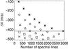 |
Fig. 4 ΔV versus the number of lines for various sets of lines for a minimum flux of 0.05 (stars), 0.2 (diamonds), 0.3 (triangles), 0.4 (squares), and 0.5 (crosses); the maximum varies between a value above the minimum up to 0.9. The horizontal line corresponds to S0. |
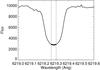 |
Fig. 5 Example of a spectral line (thin solid line) and the second-degree polynomial fit around line center (thick solid line) delimited by the two vertical dotted lines. |
For simplicity we consider only the RV uncertainty related to the RV computation, which is directly related to the S/N on the spectra and therefore to the photon noise. However, it does not include the RV uncertainty related to the instrumental stability for example, which would take the same value for all sets of lines (see Sect. 4.3 for a discussion on this issue).
 |
Fig. 6 Upper panel: α versus the number of lines for various sets of lines (same symbol code as Fig. 4). Lower panel: same, but for α versus the uncertainty ratio (rms RV for the set of lines divided by the rms RV for S0). |
2.2.4. Line set choice
Figures 4 and 6 illustrate the typical values taken by ΔV and α for different sets of lines, as a function of the number of lines identified in that set. We note that at this stage α depends only on the ΔV estimated in the previous section, not on the RVt(t) series. The value of α is also shown as a function of the ratio R defined as the ratio between the rms RV for the considered set of lines and the rms RV for S0. This allows in the following the uncertainties to be expressed as a function of the uncertainties derived for S0, closely related to the usual uncertainties in the literature: for example, the usual RV computation techniques (e.g., Galland et al. 2005) for HARPS use all lines available with associated uncertainties corresponding to this set of lines. The amplitude depends on the S/N and on the spectral type, but the usual S/N for solar-type stars in the ESO archives is in the range 0.5−1 m/s. To obtain the best reconstruction in the next sections, we know that we need to compute RV time series that are as different as possible with the best noise levels, and therefore to choose a set of lines with
-
αas far from 1 as possible;
-
R(or rms RV) as low as possible.
It should be noted that stars with identical spectral types but different levels in small-scale convection such as granulation (either on average or its temporal variability) impacting the convective blueshift, such as that derived by Meunier et al. (2017), will give a similar α if the differential velocity shift of spectral lines is universal, as pointed out by Gray (2009), because the shape of the differential velocity shift will be similar to that of Eq. (3). However, the value of α will vary for a given set of lines from one spectral type to the other because the same lines correspond to a different flux range as Eq. (3) is not linear. However, this will not be strongly affected by the level of convection itself because α is a relative variable. Our method is based the strong variability of the convective signal with time due to inhomogeneity from plages: it cannot be used if the star is quiet or when considering a large number of points over a very short time (for example one night).
 |
Fig. 7 Distribution of the excitation potentials for 2532 lines of S0 (solid line), 1146 lines of S1 (dashed line), and 1386 lines of S2 (dotted line). Line identifications were made using the spectrum of Wallace et al. (2007) and the solar spectrum available in the BASS2000 archive2, and the excitation potentials were retrieved from the VALD archive (Piskunov et al. 1995; Ryabchikova et al. 1999, 2015; Kupka et al. 1999, 2000). |
We identify two sets of lines corresponding to different compromises between the two constraints, with fluxes in the range 0.06−0.5 (S1) and 0.5−0.9 (S2). The rms RV versus σ0 (hereafter the uncertainty on RV for S0, σ0 is on the order of 0.5−1 m/s for current observations with HARPS using cross-correlation techniques with reference masks or reference spectra) is shown in Fig. 3 for two sets of lines S1 and S2 and compared to S0. The ratio between the rms RV for S1 (or S2) with the rms RV for S0 will be used in the following simulations to estimate the noise on each time series, given a RV noise level for S0. The properties of the sets used in the following are shown in Table 2 (the ratio R has been averaged over the eight S/N levels illustrated in Sect. 2.2.3 and Fig. 3). In the next sections we focus on the results obtained with the set of lines S1. Its performance level is very similar (although marginally better) to that obtained with S2. In addition, for most of the considered S/N values, S2 shows properties between the two other sets, and the difference between sets here is probably due to the number of lines in each of them (S2 includes more lines than S1). Figure 7 shows the distribution of the excitation potential for the different sets of lines for a large fraction of spectral lines. Although the dispersion is large (Chiavassa et al. 2011), the average excitation potential is lower for S1 (2.80) than for S2 (3.22).
Selected sets of line properties.
2.3. Step 1: Building of the time series for S0 and S1
We build RV time series as follows for S0 and S1 respectively:  where bi is the noise due to the RV computation added to each RV time series and the exponent “t” indicates the reference values. For S0, b0 has a rms of σ0, which varies between 0 and 1 m/s with steps of 0.01 m/s. For S1, the rms of bi(t) is R (defined in Sect. 2.2.4 and Table 2) times σ0, but the two time series b0(t) and bi(t) are not correlated. Twenty realizations of the noise are performed for each noise level.
2.4. Step 2: Choice of α and reconstructed RV time series
We consider two cases to estimate α:
-
Case 1: α is known independently with some uncertainty. We characterize the quality of the reconstructed
and for a given uncertainty on α, the exponent “r” indicating reconstructed values; -
Case 2: α is not known at all. This is the most general case. We therefore must make assumptions to solve the system in order to estimate α from our RV time series.
2.4.1. Case 1: α known with a given uncertainty
For a given α, the system described by Eqs. (4) and (5) for sets of lines S0 and S1 can be solved to provide the reconstructed RV times series:  here we consider that α may be known with a certain uncertainty; α could indeed be estimated independently from the RV series, for example by analyzing the spectra, as done by Gray (2009), Meunier et al. (2017), either for the star being studied or for the spectral type corresponding to it, or by magnetohydrodynamic numerical simulations of convection associated with the production of spectra for various spectral types (such as those produced by e.g., Ramírez et al. 2009; Chiavassa et al. 2011; Allende Prieto et al. 2013; Magic et al. 2014) that would then be analyzed as observed spectra. Such techniques to derive α, independent of the RV time series, have not yet been fully developed, but may in the future allow for a complementary computation of α. It should be noted that if the differential velocity shift of spectral lines is universal, as claimed by Gray (2009), we expect the ratio α to vary little from one star to the next, because lines tend to be deeper for lower mass (main sequence) stars. We solve the equations for two values, α − σα and α + σα, to provide a reconstruction of the RV time series in two extreme conditions; α is the true value and σα is the typical uncertainty on α.
Assumptions and methods.
2.4.2. Case 2: α unknown
For a given star, the value of α is currently not known precisely. We have therefore tested several methods based on different assumptions regarding α, RVsppl, and RVconv to estimate α from the RV time series themselves. Depending on the observation, one assumption may be better than another. This approach should also allow us to estimate the small-scale convection (such as granulation) amplitude in the star in addition to a corrected RV, for example as determined by Meunier et al. (2017). Once α is estimated using one of these methods, Eqs. (6) and (7) provide , and . The assumptions and methods are summarized in Table 3.
Method 1. We assume that ⟨ RVsppl ⟩ = 0. This is not the case for RVconv, which is positive for all time steps. We note that in the reference series  m/s and
  m/s (Table 1). We search for the value of α that leads to a reconstructed with an average of zero. The quality of the reconstruction when an offset is present is also tested (Sect. 4.1); although this assumption is correct for our simulated solar RV, this may not be the case for observed RV.
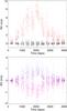 |
Fig. 8 Upper panel: reconstructed RV due to spots and plages |
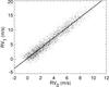 |
Fig. 9 RV1 versus RV0 for a noise of 0.5 m/s (dots) and linear fit (solid line) for the sets of lines S1 and S0, respectively. |
Method 2. We assume that the time series RVsppl(t) and RVconv(t) are uncorrelated. This is justified by the property of reference RV time series with a correlation between RVsppl(t) and RVconv(t) of 0.02, i.e., very close to zero. This is due to the different natures of the RV signal in the two cases: in the first case, the RV signal changes sign when the magnetic regions cross the central meridian (e.g., Desort et al. 2007; Lagrange et al. 2010a). In the second case, the RV signal is always positive and reaches a maximum when the structures crosses the central meridian. We therefore determine the unique value3 of α that cancels the correlation between the reconstructed and .
In the absence of noise, this technique gives a very precise value of α. However, in the presence of noise, this is not so and a correction must be performed. The reason is the following: the synthetic observed time series was built following Eqs. (4) and (5). When deriving and from RV0 and RV1 for a given αr, these reconstructed time series depend on both b0 and b1. Therefore, the noise in and is correlated, leading to a shift in the correlation: in the presence of noise, instead of searching which value of α leads to a correlation of zero, we search for the value leading to the correlation due to the noise. We assume that the amplitude of the noise is well estimated for the set of lines considered. The amplitude of this effect is estimated and corrected for.
Method 3.This method, as for the solar case, is based on the assumption that the convection signal dominates the total RV Meunier et al. (2010), and we use the relationship between RV1 and RV0. This can be checked on the reference series, especially during high activity periods, as has a rms on the order of 0.3 m/s for an average close to 0, while has a rms one order of magnitude larger and can reach values as high as 8−10 m/s as shown by Meunier et al. (2010) and in Table 1.
In that case, the slope of RV1 versus RV0 is very close to α. An example of RV1 versus RV0 is shown in Fig. 9 for a noise of 0.5 m/s, showing a slope of 0.67, while the true α is 0.70 (Table 2). We therefore perform a linear fit and derive an estimate of α from the slope.
Method 4. This method is based on the same assumption as method 3, i.e., RVconv amplitudes are much larger than RVsppl, but here we directly compare the amplitudes of the RV signal. When α is properly determined, we expect the rms of to be small. If α is not properly determined, however, RVconv can leak into the reconstructed , i.e., would include a fraction of RVconv which may not be negligible with respect to RVsppl, which would increase its rms significantly. We minimize the ratio rms of RVsppl/rms of RVconv.
Method 5. This method is based on the same assumption as the previous method, but we consider long timescale variations. We minimize the rms of RVsppl smoothed over 30 days. This method is the only one sensitive only to long timescales, while the previous ones are sensitive to all timescales. The reason is that RVconv presents some large-scale temporal variations (due to the solar cycle), while RVsppl does not; therefore, the contribution of RVconv to is easier to identify after removing the small-scale temporal variations.
2.5. Step 3: Time series reconstruction characterization
Because we know how the RVi series were built, we can compare the reconstructed αi (case 2, for five methods), and the RVs with their true reference values. We use three complementary criteria to compare the reference and reconstructed RVs:
-
The correlation between the reference and reconstructed timeseries. A very good correlation indicates that the variations in thesignal are well reproduced. We note that a correlation close to 1may be obtained even if the proper amplitude is not retrieved,hence the following complementary criteria.
-
The rms of the residuals between the reference and reconstructed series. If the performance of the correction is good, this rms should follow the noise level.
-
The correlation between
and . Although a small correlation is not sufficient to guarantee an excellent reconstruction at all timescales, a correlation different from zero means that the correction is not optimal and that the spot+plage residuals probably contain a significant part of the convection signal.
2.6. Steps 4 and 5: RV correction and performance for exoplanet detectability
Once we have obtained reconstructed times series, we correct RV0 by subtracting the reconstructed .
A straightforward estimation of the quality of the correction is obtained by directly comparing the RV time series. This is illustrated in Sect. 3.2. Given the number of simulations (for different S/N levels, methods, temporal samplings), it is also necessary to quantify the quality of the correction using some criteria so that the methods can be compared and the impact of the noise level on the performance can be studied more easily. We therefore use several complementary criteria to characterize the residuals (i.e., ):
-
The rms RV is computed and compared with the rms before correction and the best rms that can be theoretically achieved (i.e., the rms after correction with the reference
). -
The periodogram of the corrected RV is computed and the maximum power in four frequency domains is derived: 2−10 d, 10−40 d (corresponding to the rotational period and harmonics), and 100−500 d, 500−800 d (both corresponding to long-term variability during the solar cycle), also to be compared with the power computed in the same ranges before correction (i.e., on RV0) and on the time series after correction with the reference
. -
The detection limits at 480 d (corresponding to 1.2 AU), as in Lagrange et al. (2010b) and Meunier et al. (2010), are computed using the local power amplitude (LPA) method (Meunier et al. 2012; Meunier & Lagrange 2013) and compared with those before correction and after correction with the reference
. We note that we use a revised version allowing a
much faster computation, and with a slightly different threshold (Lannier et al. 2017)4.
is the sum of mostly two components: the reference and some noise coming from both b0 and b1.
3. Results
3.1. Parameters of the simulation
In this section, we perform a simulation over all points covering one solar cycle using the properties described in Table 2 for the set of line S1, with S0 used as a reference; we exclude a four-month period every year, as done in Lagrange et al. (2010a) and Meunier et al. (2010), to simulate that a given star is not observable at all times during the year, which introduces a one-year periodicity in the temporal sampling. The uncertainty on α for case 1 is chosen to be 5%. This order of magnitude corresponds to the value obtained for noise below 0.5 m/s; therefore, it is an upper limit for a relatively good S/N (if an estimation of α in other conditions leads to a higher level, a scaling of the results must therefore be applied). We first consider the case with no noise, then we consider different noise levels. We note that although the case where α is known precisely is not realistic, it should give an upper limit to what can be done in an ideal case and allows an estimation of how close other cases are to this ideal situation.
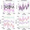 |
Fig. 10 Upper left panel: reference |
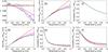 |
Fig. 11 Panel a: reconstructed α versus σ0 for S1, full temporal sampling (with a 4 month gap every year) and different methods (see Fig. 10, lower panels, for the color-coding; the curves for methods 3 and 4 are almost indistinguishable here). All noise realizations have been averaged. The true value is indicated by a solid line (only for this panel). Panel b: same, but for the rms RV of |


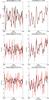 |
Fig. 12 Upper panels: reference RV component (black) and reconstructed (red) RV computed with method 1 during a period of high activity for the set of lines S1, for the spot+plage (left columns) and convection (right columns), for σ0 = 1 cm/s. Middle panels: same, but for σ0 = 10 cm/s. Lower panels: same, but for σ0 = 20 cm/s. |
3.2. No-noise case
We first consider the no-noise case. The different methods are explored and are compared with the case for which α is known precisely or with a given uncertainty.
Figure 8 (upper panel) shows the reconstructed RV for method 1 over the whole time range, which is representative of most methods used to fit α. These reconstructed RVs can be compared to the reference values shown in Fig. 1, and show a very good agreement. The lower panel of Fig. 8 illustrates the impact of a bad estimation of α: in this example (α over- or underestimated by 5%), exhibits a long-term variation representing a fraction on the order of 10% of leading to an amplitude on the order of 0.8−1 m/s due to the error on α. This illustrates the discussion for the choice of method 4 in Sect. 2.4.2.
Figure 10 shows a zoom on a limited time range during a high activity period for all cases and methods. The upper panels allow the reconstructed RVs to be compared with the reference values for case 1, i.e., α known with a 5% uncertainty, and for an exact value of α. When α is exactly known, the reconstructed RV time series are exactly the same as the reference series. For α higher or lower than the true value, however, the reconstructed values are offset by a significant amount, which is proportional to . As a consequence, , which can be used to correct the original signal for the convective contribution, differs from the true value by about 10%. This gives a good idea of the impact of the error of 5% on α on the quality of the reconstructed .
The lower panels of Fig. 10 show the difference between the reconstructed and the reference time series in case 2, with α fitted using the five different methods. The time series differs from the reference values by 1.1% (methods 1, 2, 5), 1.8% (method 3), and 2% (method 4). The differences are slightly larger for , with values between 1.9 and 3.4% depending on the method, and up to 18% for the 5% error on α case. We note that the difference is systematically negative for the spot+plage signal, and systematically positive for the convective component. This is due to the error on α: as illustrated in Fig. 8, the sign of the error on α controls the sign of the difference between reconstructed and true value.
In the absence of noise, we therefore obtain excellent reconstructed RV time series, which should allow us not only to correct properly for the convective contribution to RV, but also to study very precisely the RV variations due to activity themselves.
3.3. Impact of noise
3.3.1. Validation of the reconstructed series
We first compare the reconstructed α with the true values. The results are shown in Fig. 11 (panel a) for various σ0 and methods. For low noise levels (below 20 cm/s), the reconstructed α is very good. The reconstructed α remains within 5% of the true value up to 50 cm/s. For higher noise levels (up to 1 m/s), method 1 (within perfect conditions), always leads to good results and is therefore quite insensitive to noise. The other methods are all divergent, however.
We now compare the reconstructed RV with the reference value using the correlation between reference and reconstructed RVs and the rms RV of the difference in Fig. 11 (panels b to f). Let us consider first the reconstruction of the convective component . The rms of the difference with the reference RV series (panels b and c) naturally increases with noise, reaching ~1 m/s for a noise level around 20 cm/s. This is observed for all methods. The correlation between and (panel c) decreases as the noise increases, reaching values of 0.8 around 25 cm/s for all methods, and 0.4 for a noise above 80 cm/s.
As for , which is of great interest because it is the residual after correction of the convection signal, the rms of the difference with the reference RV series (panel d) are globally similar to the convective component. The correlation (panel e) on the other hand decreases towards 0 much faster, showing that even for low noise levels it is impossible to reproduce the temporal variation of this component in a realistic way. Only for a noise level of a few cm/s would this be possible.
Finally, the correlation between and is shown in panel f. In principle this correlation should be close to zero. If it is not the case, it means that includes a significant part of the convective signal as the large amplitude of the latter dominates the correlation. This correlation is close to zero for a noise level of just a few cm/s.
Figure 12 shows an example of reconstructed time series with method 1 during a period of high activity for three different noise levels (1, 10, and 20 cm/s). is noisier than . It is possible to recognize some short-term variations, although it is noisier than the reference signal, only for very low noise levels (cm/s). The convective signal is better reproduced up to 10 cm/s. Naturally, the very good agreement for the convective contribution is crucial because it shows that it is reasonably possible to correct for it in good conditions.
3.3.2. Performance for exoplanet detectability
We characterize the RV residuals after the correction with by computing their rms, the power of the periodogram in various ranges, and detection limits at 480 days, as described in Sect. 2.6. These detection limits can also be compared to those found by Meunier & Lagrange (2013) using a correction based on the calcium index (hereafter Ca correction). The Ca correction used in this paper represents the chromospheric emission, which is directly related to the surface covered by plages and therefore also directly related to . This is a variable that can be determined from stellar observations.
The maximum power in four period ranges is shown in Fig. 13 (panels a to d), illustrating synthetically how the periodograms evolve with noise before and after correction. The power is always increasing with σ0, all methods performing similarly. The gain in power is the best for the power in the range 100−500 d (of great interest for Earth-like planets in the habitable zone around solar-type stars) and 500−800 d, for which the gain can reach three orders of magnitude at very low noise levels. The gain is about one order of magnitude only around 0.6 m/s for the 100−500 d range. On the other hand, for the power at low periods, the gain is much smaller and a significant gain is achieved only for low noise levels: the power is the 2−10 range is higher than before correction for σ0 above 20 cm/s, and in the 10−40 d range it reaches the power before correction around 60 cm/s. When performing the correction, we therefore add a significant amount of noise at high frequencies.
Figure 14 shows a few examples of periodograms (1 out of the 20 realizations) before and after correction (only one plot is shown before correction as they are very similar for the different noise levels). The periodogram before correction shows some strong peaks in the period range of 100−800: this strong power has already been noticed by Meunier et al. (2010) and is due to variations in the filling factor of plages (and network) during the solar cycle. Figure 14 illustrates how well the power is reduced at all frequencies for a very low noise level (σ0 of 10 cm/s), with power and false alarm probabilities (fap) much lower than before correction. The 1 m/s plot exhibits a much higher power after correction, which is comparable to the power at long periods obtained when using the Ca correction for a medium Ca noise level (see Fig. 17 in Meunier & Lagrange 2013), although there is much more noise here at low periods. However, the power in the range of 100−500 days obtained for a σ0 of 50 cm/s is better than that obtained with the medium Ca noise level. The typical faps are lower than the fap before correction for σ0 below 40 cm/s, as is the maximum power: this is similar to what is obtained below when comparing the rms RV before and after correction. Finally, we note that for the example shown for 50 cm/s there are a few high peaks at periods around a few days and around 30 days: these peaks are not present for the other realizations. At the different noise levels, there are indeed a few realizations for which we do observe such peaks, most of the time below the 1% and 10% fap, but there a few cases for which they are above them. We note that for σ0 below 10 cm/s the maximum power is above the fap but corresponds to a true power (rotation modulation). We have quantified the number of such peaks as a function of noise outside the rotational modulation period range, and found that the power is higher than the 1% fap level in one realization at most.
 |
Fig. 13 Panel a: maximum power in the 2−10 d range computed on the periodogram of the RV residuals after correction versus σ0 for S1, full temporal sampling (with a 4 month gap every year) and different methods (see Fig. 10, lower panels, for the color-coding; the curves for methods 3 and 4 are almost indistinguishable here). The solid black line shows the power before correction and the dotted black line the power after correction in an ideal case (i.e., correction with the reference |
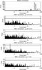 |
Fig. 14 First panel: periodogram of the simulated time series before correction (all points except for a 4 month gap), for a σ0 of 10 cm/s. From second to fifth panel: same after correction using method 1 and the set of lines S1, respectively for a σ0 of 10 cm/s, 20 cm/s, 50 cm/s, and 1 m/s. The horizontal lines show the false alarm probability (fap) at 1% (dashed lines) and 10% (solid lines). |
The rms of the residuals are shown in panel e in Fig. 13 and the detection limits in panel f. The rms remains below 1 m/s for σ0 lower than 15 cm/s, but is above the rms RV before correction above 40 cm/s. The detection limits are very low at low σ0: they are below 1 MEarth for σ0 lower than 15 cm/s. For σ0 lower than 10 cm/s, they are also below the value of 0.8 MEarth found for the Ca correction with high Ca S/N in Meunier & Lagrange (2013) for most methods. For the largest σ0, the detection limit may be better than before correction (and could correspond to the super-Earth regime), while the correction does increase the rms of residuals: this larger rms is due mostly to an increase in power at small timescales, and in these cases the correction is to be taken with caution despite the gain in detection limit.
 |
Fig. 15 First panel: fraction of realizations for which the planet amplitude after correction differs by more than 50% (black) and 10% (green) from the theoretical value. The red curve shows the 50% curve for the signal |
Finally, we performed an additional test adding a planetary signal (planet with masses 1, 2, 5, and 10 MEarth) at the same period (480 d) before applying our correction methods. Our objective is to see how the peak corresponding to the planet behaves as the noise level increases in order to check whether the correction impacts that peak. The amplitude of the peak (i.e., the power at these periods) in the periodograms for these planets alone is around 4, 16, 100, and 400, respectively, which can be compared to the power in Fig. 14. At σ0 = 10 cm/s, the planetary peak remains mostly unaffected for the four tested masses because of the low noise level. However, for higher noise levels, the number of realizations for which the planet peak amplitude is modified increases. This is illustrated in Fig. 15: the solid line shows the fraction of realizations for which the planet peak amplitude after correction differs from the expected value by more than 50% for the four planet masses. For 1 and 2 MEarth, this fraction represents more than half the realizations for σ0 above 20 cm/s and 30 cm/s, respectively, although this fraction is much lower for larger masses. The threshold of 10% is represented by the dashed lines: even for 10 MEarth, more than half the realizations lead to a difference of more than 10%. Finally, we also show the same fraction (for the 50% threshold) computed for +planet+noise, i.e., what would be obtained with a perfect correction: we also observe a significant impact on the planet peak amplitude, but smaller than the impact after correction, showing that a significant part of the variation is related to the correction. Care should therefore be taken when interpreting the planet peak amplitudes.
4. Discussion of our assumptions
4.1. Impact of assumptions in the different methods
Method 1 is very promising. However, it relies on a strong assumption: the signal is the addition of RVsppl with a zero average and of RVconv. On real observations the true zero of RVs is not necessarily known with a good precision. If an offset is added to the simulated signal the assumption is no longer true, and this indeed leads to a bias. We have tested the impact of this issue by adding an offset of 2 m/s to the simulated RV. This choice is arbitrary, but given the typical RV variations such as those in Fig. 1, we estimate that if the convection inhibition is important, it should be possible to estimate the RV zero within this uncertainty or possibly better. This is a realistic value given the average of the total signal, although for a well-observed star it may be lower. A strong bias is observed, even with no noise: instead of a value close to 0.70 we find α = 0.81, which is significantly outside the ±5% range and correspond to typical biases obtained for σ0 above 0.8 m/s for the other methods. The gain in power is very small in all period ranges, even for a very good S/N, and the detection limits remain above 10 MEarth.
In methods 3 to 5, we assume that the convection signal is much larger than the spot+plage signal. While this is true for the Sun, it may not be true for other stars. We therefore performed a similar simulation with the convective signal divided by a factor of two, so that the relative amplitude between RVconv and RVsppl is smaller (ratio divided by a factor two). Method 1 performs similarly to the previous case, but the other methods all diverge faster from the true α value as the noise increases, reaching a 3% difference around 10 cm/s. Methods 3 and 4 also show a bias on that order of magnitude even when no noise is present. However, the rms RV between the reconstructed and reference RV series are similar up to 30 cm/s and then much better (except for method 1, no decrease) than for the full convection signal for higher noise levels: although α is more poorly reconstructed, the correction performs well.
4.2. Impact of the temporal sampling
We consider now the same sampling as in our previous works, i.e., we select one point every 4, 8, and 20 days in our time series including a four-month gap, covering the full 12.5 yr duration to which we have added 12 and 16 day samplings.
The estimated α for S1 are shown in Fig. 16 for samplings of 4, 8, and 20 days and compared to the 1 day sampling. The trends are similar, but the estimation of α gets noisier as the sampling is degraded. Method 5 diverges much faster than the other methods as the sampling is degraded. For the 4 day sampling, α remains with 3% of the true value for noise below 10−15 cm/s (instead of 20−25 cm/s for the 1 day sampling), 10 cm/s for a sampling of 20 d.
Figure 17 shows the gain in terms of maximum power for different period ranges after correction for the different temporal samplings and different noise levels for method 1. For the power in range 100−500 and 500−800 d, the gain is usually larger than 1 except for high noise levels and for highly degraded sampling, and decreases as the sampling is degraded. On the other hand, the gain increases at lower periods as the sampling is degraded, and reaches 80−100 for very good noise levels and degraded sampling, while it is around 40 for good sampling.
Finally, the detection limits increase as the temporal sampling is degraded for all noise levels, as shown in Fig. 18. While for all points a 1 MEarth detection limit was obtained for noise below ~10 cm/s, this threshold falls to ~8 cm/s for the 4 day sampling and to ~4 cm/s for the 8 day sampling. It is only marginally lower than 1 MEarth for the 20 day sampling (no noise). This is not due to the correction performance, however, as a perfect removal of the convection signal leads to a detection limit close to 1 MEarth or above due to the spot+plage signal as well, as shown by the lower limit (green curves).
 |
Fig. 16 Upper left panel: reconstructed α versus the noise level for the set of lines S1 and all realizations for a sampling of 1 day (see Fig. 10 for color-coding). Upper right panel: same, but for 4 days. Lower left panel: same, but for 8 days. Lower right panel: same, but for 20 days. |
 |
Fig. 17 First panel: ratio between the maximum power (in the range 2−10 d) in the periodograms before correction and after correction (method 1) for various noise levels, showing the gain in power: no noise (solid line), 10 cm/s (dotted line), 20 cm/s (dashed line), 50 cm/s (dot-dashed line), 75 cm/s (dot-dot-dot-dashed line), 1 m/s (long-dashed line). The horizontal solid line represent a gain of A (i.e., no improvement). Second panel: same, but for the period range 10−40 d. Third panel: same, but for the period range 100−500 d. Fourth panel: same, but for the period range 500−800 d. |
 |
Fig. 18 Detection limits versus the noise levels after correction for various sampling (black lines): 1 day (solid line), 8 days (dotted line), and 20 days (dashed line), averaged over the 20 realizations of the noise. The green curves show the detection limit for |
 |
Fig. 19 First panel: detection limits versus noise for the full sample and no additional noise, averaged over all realizations. Color- and line-coding as in Fig. 13, panel f. The horizontal line is the 1 MEarth detection limit level. Second panel: same, but for binst(t) of 0.5 m/s, for one realization. Third panel: same, but for binst(t) of 0.1 m/s, for one realization. Fourth panel: same, but for binst(t) of 1 m/s, for one realization. Fifth panel: same, but for binst(t) of 0.1 m/s added to bgra(t) of 0.8 m/s, for one realization. |
4.3. Impact of other sources of noise
In this work, we considered only the RV noise due to the RV computation on noisy spectra. This noise depends on the chosen set of lines. In this section we study the impact of two other types of noise with different properties and test the impact of these contributions for all points except for the four-month gap every year (to be compared with the results shown in Sect. 3):
-
Instrumental instability: this contribution is independent of the set of lines and is exactly the same for all time series. A contribution binst(t) should therefore be added in Eqs. (4) and (5). In this work we consider a contribution of 1 m/s (corresponding to current instrumental HARPS performance), 10 cm/s (corresponding to future instruments, e.g., D’Odorico & the CODEX/ESPRESSO team 2007), and 50 cm/s (intermediate amplitude).
-
The RV noise at high frequency due to convection, and in particular granulation, should also be considered. This noise is due to the stochastic realization of many granules covering the surface at a given time. It varies from one observation to the next. This should not be confused with the convective inhibition due to magnetic fields, which is the main subject of this paper, and which varies on much longer timescales (we therefore use the term granulation in the following). We use the granulation RV time series derived by Meunier et al. (2015) in the solar case for a whole cycle (this signal is due to the different realizations of granules on the surface at each time step). The signal bgra is added to RV0 (Eq. (4)). As for RVi (Eq. (5)), we add the same time series, but modulated in amplitude because the amplitude of the granule velocities depends on the spectral lines, which controls both RVconv and bgra. We make the assumption that the factor is similar to the factor controlling ΔV and therefore add αbgra in Eq. (5). This means that bgra is corrected at the same time as RVconv.
is the same as before because binst(t) is the same in RV0 and RV1, and therefore does not impact Eq. (6). on the other hand includes that additional noise. More generally, because there is additional noise on RV0 and RV1, the estimation of α is not as good as before: the very small bias at very low noise levels observed for methods 3 and 4 (Fig. 11, panel a) is amplified to 3% (e.g.) as it is for method 2. The global trend of the reconstructed α remains very similar, however. The rms between the reference and reconstructed values is slightly larger but this is probably a direct consequence of the additional noise. The detection limits illustrated in Fig. 19 are not as good, however, with minimal values for the no-noise case around 0.5 MEarth for methods 1, 2, and 5 and close to 1 MEarth for methods 3 and 4, while they were all around 0.3 MEarth without binst. As a consequence they are lower than 1 MEarth for very small noise levels only. For binst with an amplitude of 1 m/s, the biases on α for methods 3 and 4 reaches 7% and method 2 diverges faster as well. Detection limits of 1 MEarth are only marginally achievable when there is no noise on the RV determination (apart from the binst contribution). For binst with an amplitude of 0.1 m/s, however, which should be reachable with future instruments, the results are very similar to the case with no instrumental noise as this contribution does not impact our results.
We now consider the second contribution, granulation. We add this contribution (which has a rms RV of 0.8 m/s, from Meunier et al. 2015) to an instrumental noise binst(t) of amplitude of 0.1 m/s that can be expected from future instruments. We find that the reconstructed α is very close to the value obtained without these additional noise contributions. The same is observed for the correlation and rms of the differences between the reconstructed and reference time series. The power also performs very well. For example, the power in the range 100−500 d presents a gain greater than 100 for noise below 25 cm/s. For very low noise levels (i.e., with contribution from binst and bgra only), the gain is almost 3 orders of magnitude. The impact on the correction of low level of instrumental noise and a realistic granulation time series is therefore very small. The detection limits, shown in the lower panel in Fig. 19, are below 1 MEarth for a range of noise similar to the no-granulation case, i.e., below 10 cm/s. It should be noted, however, that these detection limits are lower than those obtained with a correction with the reference . This is due to the fact that bgra behaves as RVconv, i.e., contributes with a factor α to RV1. It is therefore included in the correction made with our method, hence a small impact on our detection limits. On the other hand, after correction of the reference RVconv only, and due to the presence of bgra, the power is greater even at large periods, leading to a slightly higher detection limit.
4.4. Note on application of the method to current HARPS data
Our method leads to very good results; the detection limits are around 1 MEarth for very low noise levels, typically for σ0 lower than 10 cm/s. It is therefore difficult to apply to current HARPS data since the noise level is much higher than this. Most of the time the sampling is not as good either. In principle, a very high S/N on the spectra could be compensated by temporal averaging, however, and detection limits of a few MEarth could be obtained for higher noise levels.
We test our method on a time series of 257 spectra (covering 1800 days) obtained with HARPS for HD 207129, a G2 star exhibiting a cyclic behavior with a good correlation between the RV and Log  (0.78). Spectra and RVs (hereafter RVdrs) have both been retrieved from the ESO archives. The spectra were processed as indicated in Meunier et al. (2017), and two RV series were then extracted following the method proposed in this paper, for the sets of lines S0 and S1. The average S/N of the spectra (average over the 72 orders of the echelle spectra from the ESO archive) is around 167. The two series RV0 and RV1 are well correlated, but they show a greater dispersion at small scales than that observed for RVdrs. The correlation of RV0 and RV1 with Log is indeed weaker (around 0.4). The value of α estimated with the different techniques takes very different values, showing that it is not reliable. Similar conclusion are reached after averaging the data over 50-day bins (the number of spectra per bin is between 1 and 36), confirming that it would not be possible to apply the method on current data unless we had many more observations. Overall, the noise on RV1 is high, and after correction the time series contain the noise from both RV0 and RV1, which renders the correction impossible for this time series.
5. Conclusion
We tested a new method for correcting for the RV component due to the inhibition of convection in plages. We use different sets of spectral lines with different depths, whose dependence on the convective blueshift varies. Based on simulated RV time series, we identified a set of lines that give performance results in the solar case. We obtained the following results:
-
The set of lines must be chosen to provide a convective blueshift as different as possible from the global set of lines while still giving good S/N performance. We found that combining the global set of lines with a set selecting solar lines with fluxes (bottom of the spectral lines) in the range 0.05–0.5 gives good results. The optimal set of lines should be adapted to each star.
-
Several methods were tested to reconstruct the parameter α defined as the ratio between the convective blueshift corresponding to the restricted set of lines and the convective blueshift corresponding to the global set of lines. They give similar results overall. One of these methods is quite insensitive to the noise (with the range tested, below 1 m/s), but is biased if the zero of the RV times series is not precisely known. The other methods are not sensitive to its effect, but are very sensitive to the noise. As the different methods are based on different assumptions on the relationship between RVsppl and RVconv, it is probably better to test the different techniques for any new RV time series.
-
We find a significant improvement at low noise levels, typically below 10 cm/s (for the complete set of lines). For example, for the full temporal sampling (all points except a four-month gap each year), the power in the range 100−500 d is decreased by 3 orders of magnitude at very low noise levels. Under the conditions considered in this paper it should be possible to reach detection limits at 480 d less than 1 MEarth below 15 cm/s.
-
The results remain good with a degraded temporal sampling, although this threshold decreases significantly. The detection limits after correction also increase as the temporal sampling is degraded at all noise levels, but this is not due to the quality of the correction of the convective component, which also get worse when considering the RVsppl alone.
-
We have discussed the impact of two additional types of noise on the RV time series: the instrumental stability (short timescale) and the granulation (derived from a realistic simulation with an amplitude of 0.8 m/s). We find that the impact of the instrumental noise is very small for 10 cm/s, and has a small impact at 0.5 m/s. The addition of the granulation noise does not impact the performance significantly either, as it behaves as the convective component we focus on in this paper: as the granulation noise is highly stochastic and it is difficult to average out completely, due to the presence of power at large periods and uncorrelated with photometric time series (Meunier et al. 2015), this method may in principle be a solution to correct for this contribution as well, although other methods have been explored, such as that of Sulis et al. (2016).
When α is not equal to the proper value, RVconv contributes to the reconstructed , and the correlation is then positive (resp. negative) if α leads to an underestimation (resp. overestimation) of (see Fig. 8).
The detectability criterion is that the maximum power due to the planet in the range 0.75−1.25 Ppla (where Ppla is the planet period) is larger than 1.3 times the maximum power due to the observed signal. Computations are made for a fixed phase.
Acknowledgments
This work has been funded by the ANR GIPSE ANR-14-CE33-0018. This work has made use of the VALD database, operated at Uppsala University, the Institute of Astronomy RAS in Moscow, and the University of Vienna. This work has made use of the BASS2000 data base at http://bass2000.obspm.fr/. Our group is part of the LabEx OSUG@2020 (Investissement d’avenir – ANR10 LABX56).
References
- Aigrain, S., Pont, F., & Zucker, S. 2012, MNRAS, 419, 3147 [NASA ADS] [CrossRef] [Google Scholar]
- Allen de Prieto, C., Lambert, D. L., Tull, R. G., & MacQueen, P. J. 2002, ApJ, 566, L93 [NASA ADS] [CrossRef] [Google Scholar]
- Allen de Prieto, C., Koesterke, L., Ludwig, H.-G., Freytag, B., & Caffau, E. 2013, A&A, 550, A103 [NASA ADS] [CrossRef] [EDP Sciences] [Google Scholar]
- Boisse, I., Bouchy, F., Hébrard, G., et al. 2011, A&A, 528, A4 [NASA ADS] [CrossRef] [EDP Sciences] [Google Scholar]
- Borgniet, S., Meunier, N., & Lagrange, A.-M. 2015, A&A, 581, A133 [NASA ADS] [CrossRef] [EDP Sciences] [Google Scholar]
- Chelli, A. 2000, A&A, 358, L59 [NASA ADS] [Google Scholar]
- Chiavassa, A., Bigot, L., Thévenin, F., et al. 2011, J. Phys. Conf. Ser., 328, 012012 [NASA ADS] [CrossRef] [Google Scholar]
- Desort, M., Lagrange, A.-M., Galland, F., Udry, S., & Mayor, M. 2007, A&A, 473, 983 [NASA ADS] [CrossRef] [EDP Sciences] [Google Scholar]
- D’Odorico, V., & the CODEX/ESPRESSO team 2007, Mem. Soc. Astron. It., 78, 712 [NASA ADS] [Google Scholar]
- Dravins, D. 1987, A&A, 172, 211 [NASA ADS] [Google Scholar]
- Dravins, D. 1999, in Precise Stellar Radial Velocities, eds. J. B. Hearnshaw, & C. D. Scarfe, IAU Colloq. 170, ASP Conf. Ser., 185, 268 [Google Scholar]
- Dravins, D., Lindegren, L., & Nordlund, A. 1981, A&A, 96, 345 [NASA ADS] [Google Scholar]
- Dumusque, X., Pepe, F., Lovis, C., et al. 2012, Nature, 491, 207 [NASA ADS] [CrossRef] [PubMed] [Google Scholar]
- Dumusque, X., Boisse, I., & Santos, N. C. 2014, ApJ, 796, 132 [NASA ADS] [CrossRef] [Google Scholar]
- Galland, F., Lagrange, A.-M., Udry, S., et al. 2005, A&A, 443, 337 [NASA ADS] [CrossRef] [EDP Sciences] [Google Scholar]
- Gray, D. F. 1982, ApJ, 255, 200 [NASA ADS] [CrossRef] [Google Scholar]
- Gray, D. F. 2009, ApJ, 697, 1032 [NASA ADS] [CrossRef] [Google Scholar]
- Hamilton, D., & Lester, J. B. 1999, PASP, 111, 1132 [NASA ADS] [CrossRef] [Google Scholar]
- Kupka, F., Piskunov, N., Ryabchikova, T. A., Stempels, H. C., & Weiss, W. W. 1999, A&AS, 138, 119 [NASA ADS] [CrossRef] [EDP Sciences] [MathSciNet] [PubMed] [Google Scholar]
- Kupka, F., Ryabchikova, T. A., Piskunov, N., Stempels, H. C., & Weiss, W. W. 2000, Balt. Astron., 9, 590 [NASA ADS] [Google Scholar]
- Kurucz, R. L. 1993, CD-ROM, 13, 18 [Google Scholar]
- Kurucz, R. L., Furenlid, I., Brault, J., & Testerman, L. 1984, Solar flux atlas from 296 to 1300 nm (New Mexico: National Solar Observatory) [Google Scholar]
- Lagrange, A.-M., Bonnefoy, M., Chauvin, G., et al. 2010a, Science, 329, 57 [NASA ADS] [CrossRef] [PubMed] [Google Scholar]
- Lagrange, A.-M., Desort, M., & Meunier, N. 2010b, A&A, 512, A38 [NASA ADS] [CrossRef] [EDP Sciences] [Google Scholar]
- Landstreet, J. D. 2007, in The Future of Photometric, Spectrophotometric and Polarimetric Standardization, ed. C. Sterken, ASP Conf. Ser., 364, 481 [Google Scholar]
- Lannier, J., Lagrange, A. M., Bonavita, M., et al. 2017, A&A, 603, A54 [NASA ADS] [CrossRef] [EDP Sciences] [Google Scholar]
- Magic, Z., Collet, R., & Asplund, M. 2014, ArXiv e-prints [arXiv:1403.6245] [Google Scholar]
- Mayor, M., Pepe, F., Queloz, D., et al. 2003, The Messenger, 114, 20 [NASA ADS] [Google Scholar]
- Meunier, N., & Lagrange, A.-M. 2013, A&A, 551, A101 [NASA ADS] [CrossRef] [EDP Sciences] [Google Scholar]
- Meunier, N., Desort, M., & Lagrange, A.-M. 2010, A&A, 512, A39 [NASA ADS] [CrossRef] [EDP Sciences] [Google Scholar]
- Meunier, N., Lagrange, A.-M., & De Bondt, K. 2012, A&A, 545, A87 [NASA ADS] [CrossRef] [EDP Sciences] [Google Scholar]
- Meunier, N., Lagrange, A.-M., Borgniet, S., & Rieutord, M. 2015, A&A, 583, A118 [NASA ADS] [CrossRef] [EDP Sciences] [Google Scholar]
- Meunier, N., Lagrange, A.-M., Mbemba Kabuiku, L., et al. 2017, A&A, 597, A52 [NASA ADS] [CrossRef] [EDP Sciences] [Google Scholar]
- Piskunov, N. E., Kupka, F., Ryabchikova, T. A., Weiss, W. W., & Jeffery, C. S. 1995, A&AS, 112, 525 [NASA ADS] [Google Scholar]
- Ramírez, I., Allen de Prieto, C., Koesterke, L., Lambert, D. L., & Asplund, M. 2009, A&A, 501, 1087 [NASA ADS] [CrossRef] [EDP Sciences] [Google Scholar]
- Reiners, A., Mrotzek, N., Lemke, U., Hinrichs, J., & Reinsch, K. 2016, A&A, 587, A65 [NASA ADS] [CrossRef] [EDP Sciences] [Google Scholar]
- Ryabchikova, T. A., Piskunov, N. E., Stempels, H. C., Kupka, F., & Weiss, W. W. 1999, Phys. Scr. T, 83, 162 [NASA ADS] [CrossRef] [Google Scholar]
- Ryabchikova, T., Piskunov, N., Kurucz, R. L., et al. 2015, Phys. Scr., 90, 054005 [NASA ADS] [CrossRef] [Google Scholar]
- Sulis, S., Mary, D., & Bigot, L. 2016, ArXiv e-prints [arXiv:1601.07375] [Google Scholar]
- Wallace, L., Hinkle, K., & Livingston, W. 2007, An Atlas of the Spectrum of the Solar Photosphere from 13 500 to 33 980 cm-1 (2942 to 7405 Å) (National Solar Observatory) [Google Scholar]
All Tables
All Figures
|
Fig. 1 RV due to spots and plages (black) and convection attenuation in plages (red) in the solar case, from Meunier et al. (2010). |
| In the text | |
|
Fig. 2 Distribution of the line fluxes in the reference line set S0. |
| In the text | |
|
Fig. 3 rms RV versus S/N for set S0 (0.05–0.9, squares), S1 (0.05–0.5, stars), and S2 (0.5–0.9, diamonds). |
| In the text | |
|
Fig. 4 ΔV versus the number of lines for various sets of lines for a minimum flux of 0.05 (stars), 0.2 (diamonds), 0.3 (triangles), 0.4 (squares), and 0.5 (crosses); the maximum varies between a value above the minimum up to 0.9. The horizontal line corresponds to S0. |
| In the text | |
|
Fig. 5 Example of a spectral line (thin solid line) and the second-degree polynomial fit around line center (thick solid line) delimited by the two vertical dotted lines. |
| In the text | |
|
Fig. 6 Upper panel: α versus the number of lines for various sets of lines (same symbol code as Fig. 4). Lower panel: same, but for α versus the uncertainty ratio (rms RV for the set of lines divided by the rms RV for S0). |
| In the text | |
|
Fig. 7 Distribution of the excitation potentials for 2532 lines of S0 (solid line), 1146 lines of S1 (dashed line), and 1386 lines of S2 (dotted line). Line identifications were made using the spectrum of Wallace et al. (2007) and the solar spectrum available in the BASS2000 archive2, and the excitation potentials were retrieved from the VALD archive (Piskunov et al. 1995; Ryabchikova et al. 1999, 2015; Kupka et al. 1999, 2000). |
| In the text | |
|
Fig. 8 Upper panel: reconstructed RV due to spots and plages |
| In the text | |
|
Fig. 9 RV1 versus RV0 for a noise of 0.5 m/s (dots) and linear fit (solid line) for the sets of lines S1 and S0, respectively. |
| In the text | |
|
Fig. 10 Upper left panel: reference |
| In the text | |
|
Fig. 11 Panel a: reconstructed α versus σ0 for S1, full temporal sampling (with a 4 month gap every year) and different methods (see Fig. 10, lower panels, for the color-coding; the curves for methods 3 and 4 are almost indistinguishable here). All noise realizations have been averaged. The true value is indicated by a solid line (only for this panel). Panel b: same, but for the rms RV of |
| In the text | |
|
Fig. 12 Upper panels: reference RV component (black) and reconstructed (red) RV computed with method 1 during a period of high activity for the set of lines S1, for the spot+plage (left columns) and convection (right columns), for σ0 = 1 cm/s. Middle panels: same, but for σ0 = 10 cm/s. Lower panels: same, but for σ0 = 20 cm/s. |
| In the text | |
|
Fig. 13 Panel a: maximum power in the 2−10 d range computed on the periodogram of the RV residuals after correction versus σ0 for S1, full temporal sampling (with a 4 month gap every year) and different methods (see Fig. 10, lower panels, for the color-coding; the curves for methods 3 and 4 are almost indistinguishable here). The solid black line shows the power before correction and the dotted black line the power after correction in an ideal case (i.e., correction with the reference |
| In the text | |
|
Fig. 14 First panel: periodogram of the simulated time series before correction (all points except for a 4 month gap), for a σ0 of 10 cm/s. From second to fifth panel: same after correction using method 1 and the set of lines S1, respectively for a σ0 of 10 cm/s, 20 cm/s, 50 cm/s, and 1 m/s. The horizontal lines show the false alarm probability (fap) at 1% (dashed lines) and 10% (solid lines). |
| In the text | |
|
Fig. 15 First panel: fraction of realizations for which the planet amplitude after correction differs by more than 50% (black) and 10% (green) from the theoretical value. The red curve shows the 50% curve for the signal |
| In the text | |
|
Fig. 16 Upper left panel: reconstructed α versus the noise level for the set of lines S1 and all realizations for a sampling of 1 day (see Fig. 10 for color-coding). Upper right panel: same, but for 4 days. Lower left panel: same, but for 8 days. Lower right panel: same, but for 20 days. |
| In the text | |
|
Fig. 17 First panel: ratio between the maximum power (in the range 2−10 d) in the periodograms before correction and after correction (method 1) for various noise levels, showing the gain in power: no noise (solid line), 10 cm/s (dotted line), 20 cm/s (dashed line), 50 cm/s (dot-dashed line), 75 cm/s (dot-dot-dot-dashed line), 1 m/s (long-dashed line). The horizontal solid line represent a gain of A (i.e., no improvement). Second panel: same, but for the period range 10−40 d. Third panel: same, but for the period range 100−500 d. Fourth panel: same, but for the period range 500−800 d. |
| In the text | |
|
Fig. 18 Detection limits versus the noise levels after correction for various sampling (black lines): 1 day (solid line), 8 days (dotted line), and 20 days (dashed line), averaged over the 20 realizations of the noise. The green curves show the detection limit for |
| In the text | |
|
Fig. 19 First panel: detection limits versus noise for the full sample and no additional noise, averaged over all realizations. Color- and line-coding as in Fig. 13, panel f. The horizontal line is the 1 MEarth detection limit level. Second panel: same, but for binst(t) of 0.5 m/s, for one realization. Third panel: same, but for binst(t) of 0.1 m/s, for one realization. Fourth panel: same, but for binst(t) of 1 m/s, for one realization. Fifth panel: same, but for binst(t) of 0.1 m/s added to bgra(t) of 0.8 m/s, for one realization. |
| In the text | |
Current usage metrics show cumulative count of Article Views (full-text article views including HTML views, PDF and ePub downloads, according to the available data) and Abstracts Views on Vision4Press platform.
Data correspond to usage on the plateform after 2015. The current usage metrics is available 48-96 hours after online publication and is updated daily on week days.
Initial download of the metrics may take a while.