Fig. 5
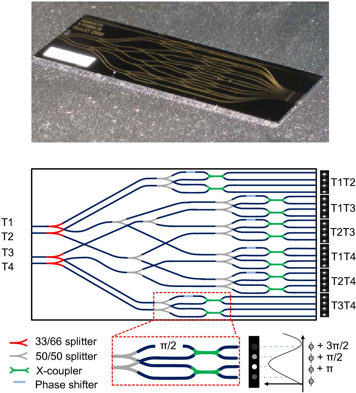
Integrated optics beam combiner: the actual interference happens in an etched silica-on-silicon integrated optics chip. The top panel shows a photograph of the GRAVITY integrated optics, the lower panel the design of the circuit. The integrated optics contain all functions (dark blue: waveguides, red and gray: beam splitter, light blue: phase shifter, green: X coupler) for a pairwise combination of the four telescopes and fringe sampling. The light from the four telescopes T1 ... T4 is fed by single-mode fibers from the left, the output on the right is the interference of the six telescope combinations for a relative phase shift of 0°, 90°, 180°, and 270°, respectively.
Current usage metrics show cumulative count of Article Views (full-text article views including HTML views, PDF and ePub downloads, according to the available data) and Abstracts Views on Vision4Press platform.
Data correspond to usage on the plateform after 2015. The current usage metrics is available 48-96 hours after online publication and is updated daily on week days.
Initial download of the metrics may take a while.