Fig. 2
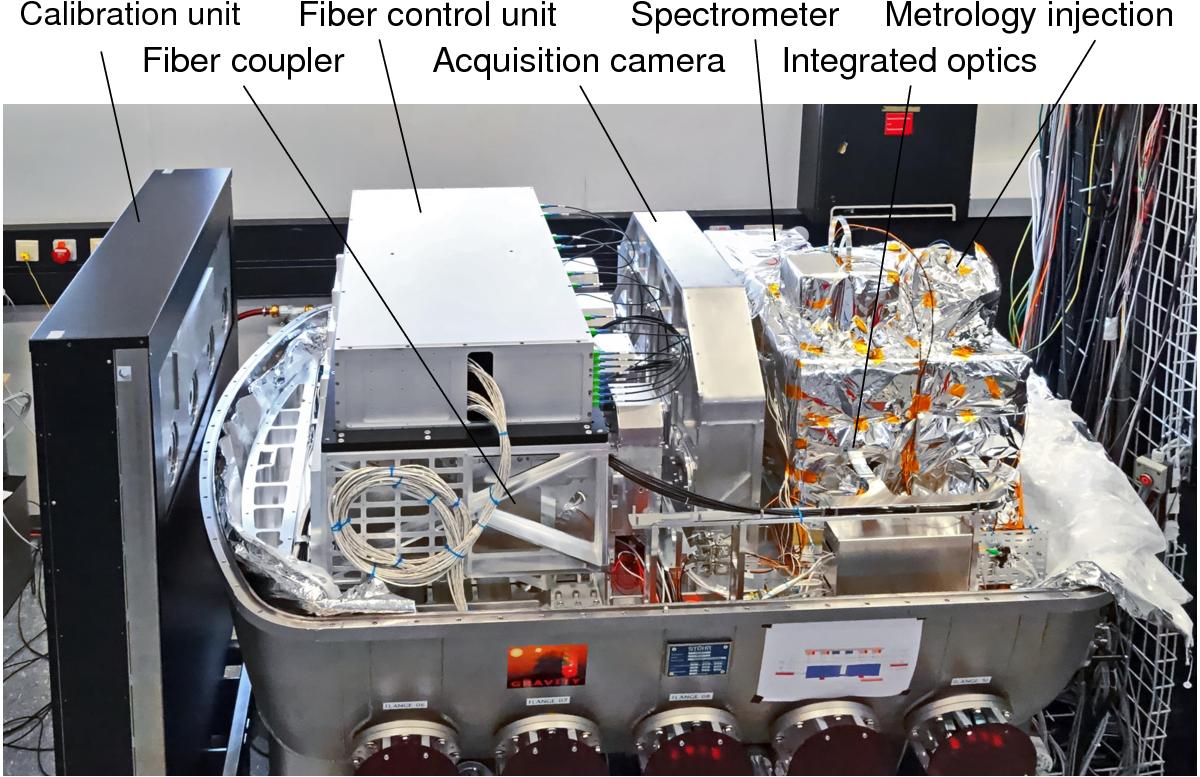
Beam combiner instrument: the photograph shows the instrument with the vacuum vessel removed to expose the subsystems. The light from the four telescopes enters from the left. The fiber couplers are located in the left part of the instrument below the fiber control unit. The acquisition camera and the receivers for the tip/tilt laser stabilization are seen in the middle of the instrument. The black cables are single-mode fibers connecting the fiber control unit with the fiber couplers and the integrated optics beam combiner. These integrated optics beam combiners are mounted to the two spectrometers − wrapped in shiny super isolation − seen on the right. The laser metrology is injected through the little “huts” − also wrapped in super isolation − on top of the spectrometers. The warm calibration unit is the black box on the very left.
Current usage metrics show cumulative count of Article Views (full-text article views including HTML views, PDF and ePub downloads, according to the available data) and Abstracts Views on Vision4Press platform.
Data correspond to usage on the plateform after 2015. The current usage metrics is available 48-96 hours after online publication and is updated daily on week days.
Initial download of the metrics may take a while.