Fig. 3
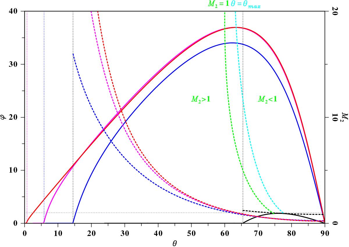
Dependence of the flow deflection angle with respect to the shock angle for different Mach numbers M1 (solid lines). The black, blue, magenta, and red lines correspond to M1 = 1.1,4,10,and100, respectively. To the right of the dotted vertical lines a physical solution exists for the corresponding Mach number, while to the left it does not. The dashed lines show the dependence of the shocked Mach number M2 from the shock angle ϑ (scale on the right vertical axis). If M1 varies, this does not lead to strong variations of ϑ around the sonic points, where M2 = 1 and ϑ ≈ 57 − 64 deg for all Mach numbers M1. But the variation of the flow deflection angle ϕ (left vertical axis) is large, as shown by the green dashed line. This line also separates the region between the weak solution (M2> 1, left from the green dashed line) and the strong solutions (M2< 1 right of the green dashed line). At this green dashed line M2 = 1 is close to the cyan dashed line, where the shock angle (ϑ) reaches a maximum.
Current usage metrics show cumulative count of Article Views (full-text article views including HTML views, PDF and ePub downloads, according to the available data) and Abstracts Views on Vision4Press platform.
Data correspond to usage on the plateform after 2015. The current usage metrics is available 48-96 hours after online publication and is updated daily on week days.
Initial download of the metrics may take a while.