| Issue |
A&A
Volume 562, February 2014
|
|
|---|---|---|
| Article Number | A8 | |
| Number of page(s) | 8 | |
| Section | Astronomical instrumentation | |
| DOI | https://doi.org/10.1051/0004-6361/201321717 | |
| Published online | 31 January 2014 | |
Instrumental polarisation at the Nasmyth focus of the E-ELT
1 Leiden Observatory, Leiden University, PO Box 9513, 2300 RA Leiden, The Netherlands
e-mail: This email address is being protected from spambots. You need JavaScript enabled to view it.
2 ASTRON, PO Box 2, 7990AA Dwingeloo, The Netherlands
Received: 16 April 2013
Accepted: 18 December 2013
Abstract
The ~39-m European Extremely Large Telescope (E-ELT) will be the largest telescope ever built. This makes it particularly suitable for sensitive polarimetric observations, as polarimetry is a photon-starved technique. However, the telescope mirrors may severely limit the polarimetric accuracy of instruments on the Nasmyth platforms by creating instrumental polarisation and/or modifying the polarisation signal of the object. In this paper we characterise the polarisation effects of the two currently considered designs for the E-ELT Nasmyth ports as well as the effect of ageing of the mirrors. By means of the Mueller matrix formalism, we compute the response matrices of each mirror arrangement for a range of zenith angles and wavelengths. We then present two techniques to correct for these effects that require the addition of a modulating device at the “polarisation-free” intermediate focus that acts either as a switch or as a part of a two-stage modulator. We find that the values of instrumental polarisation, Stokes transmission reduction and cross-talk vary significantly with wavelength, and with pointing, for the lateral Nasmyth case, often exceeding the accuracy requirements for proposed polarimetric instruments. Realistic ageing effects of the mirrors after perfect calibration of these effects may cause polarimetric errors beyond the requirements. We show that the modulation approach with a polarimetric element located in the intermediate focus reduces the instrumental polarisation effects down to tolerable values, or even removes them altogether. The E-ELT will be suitable for sensitive and accurate polarimetry, provided frequent calibrations are carried out, or a dedicated polarimetric element is installed at the intermediate focus.
Key words: instrumentation: polarimeters / methods: analytical / techniques: polarimetric / telescopes / polarization
© ESO, 2014
1. Introduction
The European Extremely Large Telescope (E-ELT) is a ~39 m optical/infrared telescope that will take ground-based astronomy to the next level (Delabre 2008; McPherson et al. 2012). Its more than 970 m2 of collecting area and unprecedented spatial resolving power will allow for revolutionary astronomical observations. Amongst the science goals of the E-ELT are the study of exoplanets and protoplanetary systems, high redshift galaxies and star formation processes (Hook et al. 2009; Liske et al. 2012). These fields are particularly demanding, observationally speaking, and will therefore benefit directly from the technological leap the E-ELT represents. However, photometry, spectrometry and imaging techniques will not be able to asses the complete spectrum of open questions without the help of polarimetry (see, e.g., Strassmeier et al. 2009).
The polarisation state of light retains information about the physical processes by which it is produced (e.g. magnetic fields, reflection and scattering, inherent asymmetries, etc., Tinbergen 1996; Clarke 2010; Snik & Keller 2013). In addition, polarimetry boosts high contrast imaging techniques by suppressing the flux from the unpolarised central star while keeping the signal from the (polarised) scattering circumstellar matter. This makes it particularly suited for direct imaging and characterisation of exoplanets and the circumstellar discs in which they are born (see Seager et al. 2000; Stam et al. 2004; Stam 2008; de Kok et al. 2011; Hashimoto et al. 2011; Quanz et al. 2011, 2012, 2013; Dong et al. 2012; Thalmann et al. 2013; Canovas et al. 2013; de Juan Ovelar et al. 2013, for some theoretical and observational examples).
Provided a proper instrument design, polarimetry and spectropolarimetry are techniques mainly limited in sensitivity (i.e., the noise level for the polarisation measurement, Snik & Keller 2013) by the amount of photons collected. However, each element in the optical path can affect the polarisation state of the light coming from the astronomical source limiting the polarimetric accuracy (Snik & Keller 2013). In terms of photon collecting power the E-ELT will be ideal for polarimetry. However, the configuration of the mirrors designed for the Nasmyth focus of this telescope is of particular complexity posing a challenge to perform accurate polarimetry at this location
The folding of light to the Nasmyth focus of telescopes is usually achieved by a 90° reflection on a mirror which generates linear (instrumental) polarisation (IP) signals of a few percent (e.g. up to a 5% at visible wavelengths Gehrels 1960; Cox 1976; Joos et al. 2008; van Harten et al. 2009; Perrin et al. 2010). Additionally, a fraction of the incoming linear polarisation is lost in the process due to conversion into circular polarisation, which is known as the “cross-talk” (CT) between linear and circular Stokes parameters. It is known that these instrumental effects can be corrected by further reflection on a second “twin” mirror positioned in a “crossed” configuration (Cox 1976). In the case of Nasmyth focus instruments, however, the mirror used to deflect the light rotates together with the telescope while the “crossed twin” usually remains fixed at the Nasmyth port causing this “crossed” configuration to only occur for certain positions of the telescope.
A retarding element positioned at the entrance of the Nasmyth port can be used to de-rotate the polarisation such that it is always compensated by the “twin" mirror (Sanchez Almeida et al. 1995; Tinbergen 2007). This solution has been successfully applied to the design of ZIMPOL (see de Juan Ovelar et al. 2012), the polarimeter of the VLT’s planet finder SPHERE (Gisler et al. 2004; Stuik et al. 2005; Beuzit et al. 2006; Thalmann et al. 2008; Roelfsema et al. 2010; Schmid et al. 2010). In the particular case of the E-ELT, this solution is not applicable since the size of the light beam at this location is too large for the currently available high-quality retarders. Additionally, in the E-ELT the Nasmyth folding is achieved through consecutive reflection on a minimum of two and a maximum of three mirrors instead of one depending on the finally chosen design. To perform accurate polarimetry with the E-ELT it is therefore crucial to analyse the polarisation properties of the optical design and either correct for or calibrate any instrumental polarisation effects.
In this paper, we quantitatively characterise the polarisation properties of the two currently proposed Nasmyth optical designs of the E-ELT and analyse two techniques to reduce the instrumental effects. The study is organised as follows. In Sect. 2 we briefly describe the basics of our modeling approach while in Sect. 3 we describe the details of the simulations performed. Sect. 4 describes the results obtained and discusses an example of ageing effects on the mirrors after calibration and Sect. 5 describes the solutions proposed to correct for the instrumental effects found. Finally Sect. 6 presents a discussion of the results obtained and the conclusions of our study.
2. Modeling approach
We use the performance simulator for polarimetric systems code M&m’s (de Juan Ovelar et al. 2011) to compute the instrumental polarisation effects generated in the optical path of the E-ELT telescope up to the Nasmyth focus. By means of the Mueller matrix formalism, the code calculates the polarisation properties of a given optical system as well as the effects of the measurement process followed.
In this formalism the polarisation state of light is described by a 1 × 4 vector known as the Stokes vector, S = (I,Q,U,V)T, where I is the intensity, Q and U are linear polarisations in the 0 / 90° and ± 45° directions and V is circular polarisation (symbols in boldface denote matrices or vectors). The effect that an optical element has on the polarisation state of light passing through it, can be described as the product between the incoming Stokes vector (Sin) and a 4 × 4 matrix that accounts for the polarisation properties of the element (i.e. a Mueller matrix M),  (1)The same holds for an optical system composed of several elements,
  (2)where Mn...M1 represent the Mueller matrices of the n elements of the optical system with 1 being the first element in the optical path and n being the last.
In order to measure the Stokes components the modulation and demodulation steps need to be included in the process. The first one consists of “encoding” the polarisation state of the incoming light in a set of intensity measurements that can be registered by the detector and is usually performed by two elements in the polarimeter: the modulator and the analyser. The former modifies the state of the incoming polarisation, while the latter acts as a polarisation “filter”. By changing the position of the modulator in particular steps (i.e. modulation scheme), one can control which polarisation (Q, U or V, or a linear combination thereof) passes through the analyser and is contained in the measured intensity (Imeas,i, with i ranging from 1 to m and m being the total number of intensity measurements performed, as well as the positions/states of the modulator). This process can be described by the “modulation matrix” (O) which then relates the incoming Stokes vector to the 1 × m measured intensity vector (Imeas = (I1,I2,...,Im)T),  (3)where each row in O is the first row of the Mtotal matrix of the system at each modulation state m. Each component of the incoming Stokes vector can then be obtained from a linear combination of these m intensity measurements, a process that is known as demodulation,
  (4)which yields the “measured” Stokes vector (Smeas).
The complete polarimetric measurement process (i.e. including optical system properties, modulation and demodulation steps) can then be represented by a matrix that is often known as the “response matrix” (X, Ichimoto et al. 2008) which relates the incoming Stokes vector with the measured Stokes vector,  (5)where X = DO.
The response matrix is a 4 × 4 matrix that therefore includes the effect of both the optical system and the defined modulation/demodulation schemes. This makes it a powerful tool for diagnosing the impact of systematic effects on the polarimetric capabilities of any optical system accounting for the modulation/demodulation processes.
The results obtained in this study are presented in terms of the response matrix and to facilitate their analysis Eq. (6) shows the relation each of its element represents,  (6)Diagonal elements represent the fractional transmission of a Stokes component throughout the measurement process. Elements in the first column (Iin → Q,U,Vmeas) give the polarisation that is generated by the system (IP). Elements relating Qin,meas and Uin,meas are known as rotation while the ones relating Qin,meas or Uin,meas with Vin,meas give the cross-talk (CT). In presenting our results, we analyse the CT focussing on elements X3,2,X4,2 and X4,3.
Provided a set of optical elements and the modulation/demodulation schemes, the M&m’s code computes all Mueller matrices of the elements and generates the Mtotal, O, D and X of the system. In obtaining X the code either computes D as the inverse or pseudo-inverse of O, depending on the particular case (del Toro Iniesta & Collados 2000), or requires the user to specify it. In the simulations presented in this study we define the demodulation matrix such that it corresponds to an ideal polarimeter. The reason for this is that our aim is to model the behaviour inherent to the optical arrangement and the impact the modulation has on it and not the behaviour of the polarimeter. In this way, the matrix O includes the realistic behaviour of the elements in the optical system while D is only computed for the ideal polarimeter. This will cause the response matrix to show the behaviour of the optical system including the modulation scheme but not any effects from the polarimeter.
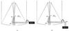 |
Fig. 1 Mirror arrangements considered for the E-ELT Nasmyth configuration with mirrors and intermediate focus (IF) of the telescope marked. a) Straight-through configuration, with the Nasmyth focus directly after the fifth reflection. b) Lateral configuration, with a sixth mirror fixed in the Nasmyth port. The Q, U, V box represents a perfect full-Stokes polarimeter at the corresponding Nasmyth focus. The rotation axis of the telescope and the ± Q directions at the intermediate focus position are indicated. Adapted from Delabre (2008). |
Some other considerations regarding our simulations are
-
1.
The dispersion of the index of refraction with wavelength is included for all materials used. However, for the thin amorphous alumina layer on top of the mirrors a constant value of n = 1.6 was assumed, which is an approximation of the value in the studied region ([500 − 900] nm, Eriksson et al. 1981).
-
2.
Unless explicitly noted, all mirrors have the same characteristics, i.e. no differential effects are included.
-
3.
Whenever available, real material characteristics and design parameters are used to describe optical elements.
-
4.
The Mueller matrices have only been established for the chief ray and therefore the centre of the field of view.
-
5.
Only ideal Mueller matrices are taken into account, i.e. deviations from the characteristic values of the parameters of optical elements are not included.
-
6.
The efficiency of the detector is assumed to be perfect.
-
7.
We quantify polarisation effects that can be described with Mueller matrices. We therefore disregard polarisation effects that may be brought about by, e.g., (residual) seeing, differential aberrations, or diffraction effects. As such, the results presented here are for the average of the point spread function (PSF) of the telescope (Sanchez Almeida & Martinez Pillet 1992)
3. E-ELT Nasmyth configurations
Figure 1 shows the positions of the E-ELT mirrors in the two Nasmyth configurations considered by the current optical design. In the first one (Fig. 1a), straight-through hereafter, the light is sent to the Nasmyth focus after reflection on the five mirrors fixed to the telescope. These mirrors, therefore, rotate with the zenith angle around the Nasmyth ports as the telescope tracks. The second set up considered, lateral hereafter, adds a sixth mirror fixed at the Nasmyth port (Fig. 1b). The first three mirrors (M1, M2 and M3) are rotationally symmetric, which makes their contribution to the instrumental polarisation effects negligible (Sanchez Almeida & Martinez Pillet 1992). Therefore, we only consider the effect of mirrors [M4, M5] or [M4, M5, M6] when simulating the straight-through and lateral arrangements respectively. All mirrors are made out of aluminum (index of refraction obtained from Rakic 1995) and have a 4 nm Al2O3 layer adopted from the measurements of van Harten et al. (2009). Mirrors M4, M5 and M6 have incidence angles of 8.5°, 36.5° and 45° respectively. We consider a range of telescope zenith angles of z = [0−90] deg and wavelengths of λ = [500 − 900] nm, and a temperature of T = 10°C.
We define the reference system to be fixed to the telescope which is equivalent to having the instrument physically co-rotating at the Nasmyth port (e.g. pupil tracking), implementing a half-wave plate in the instrument that converts the coordinate system of the telescope to the local one, or de-rotating the data obtained during the data reduction. The + Q direction is defined as being aligned with the s − direction of mirror M4, see Fig. 1. With the + Q direction as a reference, the Stokes + U direction is defined to be rotated clockwise by 45° as we look into the direction of propagation of the light, and Stokes + V is defined to be rotating counterclockwise.
The total Mueller matrices of both optical arrangements are then computed by the code as:  (7)and
  (8)where M stands for Mueller matrices of mirrors and R for Mueller matrices of rotations.
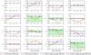 |
Fig. 2 Normalised response matrices (X) versus zenith angle (z) obtained for the E-ELT’s two Nasmyth configurations considered and for the approximated limits of the wavelength range studied (λ = [550,850] nm). Solid and dashed lines correspond to the lateral and straight-through configurations, respectively. Plus and cross markers denote wavelengths of λ = [550,850] nm, respectively. The light-green areas represent the range of values inside the requirements adopted in this study (see Sect. 3). |
To simulate the ideal polarimeter we implement a perfect modulator using perfect half-wave and quarter-wave plates (HWP and QWP) to measure Stokes Q,U and V, respectively. The HWP rotates the direction of the incoming linear polarisation with respect to its fast axis. The QWP transforms circular polarisation into linear polarisation depending also on the orientation of its fast axis. The QWP is therefore included in our simulations only for the modulation states where we want to measure V. The analyser is a perfect polariser aligned with the + Q direction of the (rotating) reference system.
We then specify a six-step modulation scheme to encode the Q, U and V Stokes components and an (ideal) demodulation matrix that recovers them. While the modulation scheme can be used for both configurations of the E-ELT considered here, the demodulation matrix has to be designed specifically for each case since the additional mirror has an effect on how the Stokes components are encoded. Table 1 shows the modulation scheme used and the Stokes component that each modulation state encodes for the two setups simulated.
Modulation scheme for E-ELT straight-through and lateral configurations.
Finally, we consider the following requirements for each element of the response matrix, based on those set for the high-contrast imaging polarimeter E-ELT/EPICS-EPOL (Keller et al. 2010):
-
linear IP (i.e. I → Q,U) <0.1%;
-
transmission of linear polarisation (i.e. Q → Q and U → U) >95%;
and high-resolution spectropolarimeters such as ESPaDOns and HARPSpol (Barrick et al. 2010; Snik et al. 2011)
-
cross-talk (Q,U ↔ V) <1%.
4. Response matrices of the E-ELT Nasmyth configurations and effect of mirror ageing
4.1. Response matrices
Figure 2 shows the response matrix for the two arrangements studied, normalised to the measured intensity (i.e. element X1,1), as a function of the zenith angle of the telescope. Solid and dashed lines correspond to the lateral and straight-through configurations, respectively, while plus and cross markers denote wavelengths of λ = [550,850] nm, the approximated limits of the wavelength range studied. The light-green areas represent the range of values of each element that falls inside the requirements defined above. Note that, in this particular cases, the modulation scheme is such that, when using the ideal demodulation matrix, the response matrix X coincides with the Mueller matrix of the systems.
-
(a)
Straight-through Nasmyth configuration: M4-M5-Nasmyth focus Dashed blue lines in Fig. 2 show the values of the elements of the response matrix in this configuration. Here, the reference system is fixed to the telescope because mirrors M4 and M5 rotate together with it. This causes the response matrix to be independent of the zenith angle. This reference system can easily be implemented in any instrument by e.g. making the instrument co-rotate with the telescope, placing a retarding element before the instrument capable to de-rotate de polarisation, or de-rotating via the data reduction. In terms of instrumental polarisation (elements X1,2,X1,3,X1,4) only Stokes Q is generated by this system (element X1,2) with values in the range of ~ [2 − 3.4] % depending on the wavelength. These values fall well out of the requirements (light-green area). Because the polarimeter is aligned with the Q direction of the system and it rotates together with the telescope, Stokes Q is transmitted without loss throughout the measurements process (element X2,2). The transmission of Stokes U and V (X3,3 and X4,4) varies depending on the wavelength well within the requirements defined for these elements. Cross-talk here only occurs between linearly polarised light in the U direction and circularly polarised light V (X4,3), with values in the range of ~ [12 − 16] %, outside of the 1% required.
-
(b)
Lateral configuration: M4-M5-M6-Nasmyth focus Solid yellow lines in Fig. 2 show now the values of the elements of the response matrix in the lateral configuration, again with plus and cross markers denoting values for wavelengths of λ = [550,850] nm, respectively. The configuration includes now one more mirror (M6) fixed in the Nasmyth platform. Since the reference system is fixed with respect to the telescope (i.e. moves together with M4 and M5), the system behaves “as if” M6 would be rotating with the zenith angle, which introduces a dependency of the response matrix with the zenith angle. Both linear and circular instrumental polarisation are now generated and vary with the zenith angle. Stokes Q remains outside the specifications for all zenith angles other than z = 25° (element X1,2). Whereas in the case of Stokes U and V, the requirements are only met at angles of z = [0,90] ° (elements X1,3 and X1,4). Transmission of all Stokes components (diagonal elements) remains within the requirements except for the case of U and V at long wavelengths and for zenith angles larger than z > 65° (elements X3,3,X4,4). Here, the cross-talk takes place between both Stokes Q and U and Stokes V, and it varies with the zenith angle. In the first case (element X4,2) the values fall only inside the requirements for zenith angles of z = [0,90] °. In the case of cross-talk between U and V (X4,3) that only happens for z = 25°.
 |
Fig. 3 Variations in the response matrix of the lateral Nasmyth case due to uncalibrated variations in mirror properties. Solid red line shows the values for the elements after calibration at λ = 650 nm, and dotted grey lines the deviations caused by the ageing. The areas shaded in green represent the requirements for polarimetric accuracy (See Sect. 1). |
4.2. Effect of ageing of mirrors after calibration
It is clear that the E-ELT mirrors produce instrumental polarisation effects that are in many cases considerably outside of the requirements set. The first question to answer is whether these effects can be calibrated to the required accuracy. A comprehensive simulation of calibration procedures is beyond the scope of this paper. However, for a first estimate of the calibrability, we can compute the impact that variation on mirror properties have on the response matrix.
For this exercise, we use the lateral Nasmyth configuration and assume a perfect calibration of the instrumental effects found. We then vary the properties of M4, M5 and M6 such that it mimics the effects of ageing and mirror pollution, which are the major contributors to the variation in the polarisation properties of telescope mirrors. To this aim we 1) vary the effective thickness of the dielectric layer on the mirror (df) by 1 nm, corresponding to a decrease in mirror reflectivity of ~10% due to the build-up of dust and grime on top of the mirrors; and 2) we vary the absorption term for the mirrors (Im(nm)) by 10%, to represent ageing effects (Joos et al. 2008). The variation of these two parameters are positively correlated (Snik & Keller 2013). We assume that these variations are independent for M4, M5 and M6, and can go in both directions as mirror cleaning or recoating can take place before or after the calibration.
Figure 3 presents the deviations upon the X matrix in the lateral Nasmyth case for all cases of variations in mirror properties after perfect calibration has taken place. These uncalibrated effects alone make system fall out of the requirements in the case of linear IP and CT between U and V. Therefore, frequent calibrations need to take place for polarimetric E-ELT instruments to operate within requirements.
5. Correction of the instrumental effects: switch and two-stage modulation techniques
A method for correcting the instrumental effects has to modify the response matrix of the system which, as explained in Sect. 2, depends on the Mueller matrix of the optical system and on the modulation/demodulation process. The correction, therefore, can be achieved either modifying the instrument, e.g. adding elements in the light path that compensate the polarisation effects or adapting the polarisation modulation, or any combination of both.
The first approach is, mathematically speaking, equivalent to intrinsically modifying the Mueller matrix of the optical system. In the second one, additional modulation steps are introduced to separate the instrumental polarisation effects from the source polarisation, and consecutively be minimised with an additional, differential measurement.
In this section we present two techniques of the second type, the switch and 2-stage modulation techniques. We apply them to the correction of the instrumental effects generated on the E-ELT lateral configuration, found to be the least optimal for performing accurate polarimetry. In both cases, retarding elements are placed in the intermediate focus of the telescope (see below) to modify the modulation scheme. To fully characterise the effect of these elements in the measurement process, they are always simulated as realistic wave-plates, while the retarders used for the polarimeter are still simulated as ideal elements. The D matrix is still computed for an ideal polarimeter.
5.1. The switch technique
The switch technique is a simple modulation-related technique to apply (Tinbergen 1996; Stuik et al. 2005). The idea is to implement a rotatable wave-plate as early in the light path as possible to “switch” the sign of the incoming polarisation while keeping the instrumental effects, generated downstream, fixed. In the case of the E-ELT, this element could be installed in the intermediate focus (IF) of the telescope (see Fig. 1). Light passes through this IF on its way from M2 to M3 and therefore, before reaching M4, which makes this focus “polarisation-free”. This wave-plate, the switch hereafter, rotates the direction of the either linear or circular polarisation coming from the sky and the telescope up to this point (i.e. sky-M1-M2-M3), alternatively between two orthogonal positions, thus changing its sign. However, the polarisation generated along the optical path of the telescope below (i.e. M4-M5-M6) remains unrotated. By taking two sets of measurements with the switch in these two positions and subtracting them, one can ideally suppress most of the instrumental polarisation generated in the Q and U directions.
A potential disadvantage of this technique comes from the fact that the two measurements are taken with a delay in time. If the measurements are separated in time they might end up being slightly different and the subtraction is not perfect anymore. Therefore, the technique benefits from a rapid switching/modulation duty cycle.
Modulation scheme for E-ELT lateral configuration (M4-M5-M6) + IF-switch.
To show how this arrangement would correct the linear IP in the lateral case, we simulate the IFswitch with a HWP at the intermediate focus (HWPif) rotating between 0 / 45° and therefore correcting the instrumental polarisation generated in the Q direction. Table 2 shows the resulting modulation scheme. This element is simulated using realistic specifications of an achromatic HWP. The element is composed of two crossed birefringent plates made of quartz and magnesium fluoride (MgF2) with thicknesses tquartz = 841.2 μm and tMgF2 = 674.8 μm. These two plates together comprise an achromatic HWP with a working range of λ = 500 − 900 nm centred at λ = 650 nm. Refractive indices for quartz and magnesium fluoride were obtained from Ghosh (1999) and Bass et al. (2009), respectively.
The wavelength range of the HWP is the limiting factor of this solution since, any deviation from a perfect half-wave plate will affect the switching performance. Table 2, shows the positions of all elements involved in the modulation.
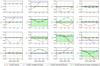 |
Fig. 4 Normalised response matrices (X) versus zenith angle (z) obtained for the four configurations simulated at λ = 650 nm. Solid, dot-dashed, dotted and dashed lines correspond to the lateral, straight-through, straight-through+IFswitch and lateral+IFswitch configurations. |
5.2. The 2-stage modulation technique
The switch technique solves the issue of the polarisation generated in the system for either linear or circular polarisation (not both). However, the same principle can be taken further to develop a 2-stage modulation technique. In this case, a full-blown polarisation modulator is located in a “polarisation-free” location upstream (in this case, again, the IF of the E-ELT). This modulator converts the measureable polarisation into a polarisation state that is mostly or fully transmitted by the optical system behind it, known as the “eigen-vector” of the system (Lopez Ariste & Semel 2011; Snik & Keller 2013). For relatively simple cases, this eigen-vector is linear polarisation, e.g. + Q for the straight-through Nasmyth port case. In general, this eigen-vector is elliptical, and varies with the instrument configuration, e.g. the pointing in the lateral Nasmyth case.
We apply such a two-stage modulator for the E-ELTe placing a modulator in the IF that consists of two achromatic wave plates: HWPif and QWPif. The QWPif is implemented in the same way as the HWPif of Sect. 5.1 by modifying the thicknesses of the two layers, tquartz = 421.1 μm and tMgF2 = 337.8 μm, to make it a quarter-wave plate. These plates (HWPif and QWPif) are used to modulate Q, U and V in a classical way by sequentially converting those polarisation states into Q. This direction is not an eigen-vector for the lateral Nasmyth case, but it comes sufficiently close. The polarimeter on the Nasmyth platform now only measures Stokes Q, which allows for a much faster duty cycle than the first modulator in the IF. Table 3 shows the position of the elements for this modulation scheme.
Modulation scheme for E-ELT lateral configuration (M4-M5-M6) + 2-stage modulation.
5.3. Corrected response matrix
Figure 4 shows a comparison of the four configurations analysed in this study, i.e. E-ELT lateral, E-ELT straight-through, E-ELT lateral+IFswitch and E-ELT lateral+2-stage modulation. The elements of the four response matrices are shown for a fixed wavelength of λ = 650 nm, which is the centre of the wavelength range studied. Solid lines correspond to the original straight-through and lateral matrices (blue unmarked and yellow star-marked, respectively) while dashed green lines correspond to the corrected ones, with plus and cross markers denoting values for lateral+IFswitch and lateral+2-stage modulation, respectively.
Linear IP is completely suppressed by the two methods (elements X1,2, and X1,3) while circular IP is only compensated for in the lateral+2-stage modulation case. The CT between Q and V is improved only in the lateral+IFswitch solution while that taking place between U and V is significantly improved in this same case and completely corrected for in the lateral+2-stage modulation arrangement. This technique also improves considerably the transmission of all Stokes vectors while the lateral+IFswitch only meet the requirements for zenith angles of z ≤ 65. The rotation element, X3,2, presents, however, a much worse behaviour for the lateral+2-stage modulation case.
6. Discussion and conclusions
The results shown in Fig. 2 show that, according to the requirements set, none of the two Nasmyth configurations being considered for the E-ELT are suitable for performing accurate polarimetry. However, the instrumental effects generated in the straight-through configuration, i.e. IP in the Q direction and CT between U and V, are at least independent of the pointing of the telescope when adopting a coordinate system that co-rotates with the telescope which makes it relatively easy to correct for (e.g., using a tilted glass plate to compensate the IP).
Depending on the science requirements, calibration can be a good enough solution to the problem. However, the time required to perform calibration measurements for polarimetry is considerably long due to the fact that photometric and polarimetric measurements are needed as well as a similar signal to noise ratio in both the science and calibration observations. As an example, in current polarimetric observations of circumstellar environments, up to a 50% of the observing time can be lost between calibration with polarimetric standard stars and overheads.
The frequency with which calibration measurements have to be performed is also an important parameter to account for since, as shown in Sect. 4.2, small variations in parameters of the optical elements can quickly impact the quality of the measurements.
It is in the light of this conclusion that we propose alternative solutions based on extended modulation approaches to correct for the instrumental effects. The switch and two-stage modulation techniques are applied to the lateral Nasmyth configuration and their response matrices computed for the same range of zenith angles and wavelengths considered before. Figure 4 shows how most of the instrumental effects are stabilised and/or corrected for. In general, the switch technique works very well for systems that are focussed on the measurement of linear polarisation while the 2-stage modulation has the potential of taking care of circular polarisation issues as well. An additional advantage of the latter implementation is the better response of the system to the measurement of U (see element X3,3 of Fig. 4) In short, the 2-stage modulation improves the efficiency of the polarimeter by tuning the eigen-vector of the system to the Stokes component that is being measured. This, in the framework of our simulations, comes at the price of increasing the rotation between Q and U and the CT between Q and V. However, it is important to remark that our modulation scheme is just an example and that different modulation schemes can be optimised to compensate for the particular instrumental effects a given observation has to deal with.
These effective and versatile techniques require the addition of retarding elements to the optical path of the telescope which, considering the already complex optical design of the E-ELT, may be a disadvantage. However they also have the advantage of decreasing the calibration time required. The retarding elements used in the cases presented in this study also introduce
a higher dependency of the values of the response matrix with wavelength, although this depends strongly on the design of the retarder(s) and, in principle, it is feasible to taylor them to suit the requirements of a particular case.
In summary, the E-ELT poses considerable challenges to performing accurate polarimetry, but with the current state of polarimetric techniques it is definitely possible to achieve this goal.
Acknowledgments
The authors are grateful to Tim van Werkhoven, Visa Korkiakoski, David Harrington and Gerard van Harten for insightful discussions and to the anonymous referee for a very useful report that helped improve this study.
References
- Barrick, G., Benedict, T., & Sabin, D. 2010, in Proc. SPIE, 7735, 4C [Google Scholar]
- Bass, M., DeCusatis, C., Enoch, J., et al. 2009, Handbook of Optics, 3rd edn. Vol. IV, Handbook of Optics (McGraw-Hill Education) [Google Scholar]
- Beuzit, J.-L., Feldt, M., Dohlen, K., et al. 2006, The Messenger, 125, 29 [NASA ADS] [Google Scholar]
- Canovas, H., Ménard, F., Hales, A., et al. 2013, A&A, 556, A123 [NASA ADS] [CrossRef] [EDP Sciences] [Google Scholar]
- Clarke, D. 2010, Stellar Polarimetry (Wiley) [Google Scholar]
- Cox, L. J. 1976, MNRAS, 176, 525 [NASA ADS] [Google Scholar]
- de Juan Ovelar, M., Snik, F., & Keller, C. U. 2011, in Proc. SPIE, 8160, 8 [Google Scholar]
- de Juan Ovelar, M., Diamantopoulou, S., Roelfsema, R., et al. 2012, Proc. SPIE, 8449, 12 [NASA ADS] [Google Scholar]
- de Juan Ovelar, M., Min, M., Dominik, C., et al. 2013, A&A, 560, A111 [NASA ADS] [CrossRef] [EDP Sciences] [Google Scholar]
- de Kok, R. J., Stam, D. M., & Karalidi, T. 2011, ApJ, 741, 59 [NASA ADS] [CrossRef] [Google Scholar]
- del Toro Iniesta, & Collados, M. 2000, Appl. Opt., 39, 1637 [NASA ADS] [CrossRef] [PubMed] [Google Scholar]
- Delabre, B. 2008, A&A, 487, 389 [NASA ADS] [CrossRef] [EDP Sciences] [Google Scholar]
- Dong, R., Rafikov, R., Zhu, Z., et al. 2012, ApJ, 750, 161 [NASA ADS] [CrossRef] [Google Scholar]
- Eriksson, T. S., Hjortsberg, A., Niklasson, G. A., & Granqvist, C. G. 1981, Appl. Opt., 20, 2742 [NASA ADS] [CrossRef] [Google Scholar]
- Gehrels, T. 1960, AJ, 65, 466 [NASA ADS] [CrossRef] [Google Scholar]
- Ghosh, G. 1999, Optics Commun., 163, 95 [NASA ADS] [CrossRef] [Google Scholar]
- Gisler, D., Schmid, H. M., Thalmann, C., et al. 2004, Proc. SPIE, 5492, 463 [Google Scholar]
- Hashimoto, J., Tamura, M., Muto, T., et al. 2011, ApJ, 729, L17 [NASA ADS] [CrossRef] [Google Scholar]
- Hook, I., Liske, J., Villegas, D., & Kissler-Patig, M. 2009, The Messenger, 137, 51 [NASA ADS] [Google Scholar]
- Ichimoto, K., Lites, B., Elmore, D., et al. 2008, Sol. Phys., 249, 233 [NASA ADS] [CrossRef] [Google Scholar]
- Joos, F., Buenzli, E., Schmid, H. M., & Thalmann, C. 2008, in Proc. SPIE, 7016, 48 [Google Scholar]
- Keller, C. U., Schmid, H. M., Venema, L. B., et al. 2010, in Proc. SPIE, 7735, 212 [Google Scholar]
- Liske, J., Padovani, P., & Kissler-Patig, M. 2012, Proc. SPIE, 8444, 1I [Google Scholar]
- Lopez Ariste, A., & Semel, M. 2011, in ASP Conf. Ser., Solar Polarization 6, eds. J. R. Kuhn, D. M. Harrington, H. Lin, et al., 437, 403 [Google Scholar]
- McPherson, A., Gilmozzi, R., Spyromilio, J., Kissler-Patig, M., & Ramsay, S. 2012, The Messenger, 148, 2 [NASA ADS] [Google Scholar]
- Perrin, M. D., Graham, J. R., Larkin, J. E., et al. 2010, in Proc. SPIE, 7736, 192 [Google Scholar]
- Quanz, S. P., Schmid, H. M., Geissler, K., et al. 2011, ApJ, 738, 23 [NASA ADS] [CrossRef] [Google Scholar]
- Quanz, S. P., Birkmann, S. M., Apai, D., Wolf, S., & Henning, T. 2012, A&A, 538, A92 [NASA ADS] [CrossRef] [EDP Sciences] [Google Scholar]
- Quanz, S. P., Avenhaus, H., Buenzli, E., et al. 2013, ApJ, 766, L2 [NASA ADS] [CrossRef] [Google Scholar]
- Rakic, A. D. 1995, Appl. Opt., 34, 4755 [NASA ADS] [CrossRef] [Google Scholar]
- Roelfsema, R., Schmid, H. M., Pragt, J., et al. 2010, Proc. SPIE, 7735, 4B [Google Scholar]
- Sanchez Almeida, J., & Martinez Pillet, V. 1992, A&A, 260, 543 [NASA ADS] [Google Scholar]
- Sanchez Almeida, J., MartinezPillet, V., & Kneer, F. 1995, A&AS, 113, 359 [NASA ADS] [Google Scholar]
- Schmid, H. M., Beuzit, J. L., Mouillet, D., et al. 2010, in Proc. Conf. the Spirit of Lyot 2010, ed. A. Boccaletti [Google Scholar]
- Seager, S., Whitney, B. A., & Sasselov, D. D. 2000, ApJ, 540, 504 [NASA ADS] [CrossRef] [Google Scholar]
- Snik, F., & Keller, C. U. 2013, Planets, Stars & Stellar Systems, eds. T. D. Oswalt, H. Bond (Springer) [Google Scholar]
- Snik, F., Kochukhov, O., Piskunov, N., et al. 2011, in Solar Polarization 6, ASP Conf. Ser. 437, 237 [Google Scholar]
- Stam, D. M. 2008, A&A, 482, 989 [NASA ADS] [CrossRef] [EDP Sciences] [Google Scholar]
- Stam, D. M., Hovenier, J. W., & Waters, L. B. F. M. 2004, A&A, 428, 663 [NASA ADS] [CrossRef] [EDP Sciences] [Google Scholar]
- Strassmeier, K. G., et al. 2009, E-ELT Spectropolarimetry: The Science Case, available at http://www.eso.org/sci/facilities/eelt/science/doc/ [Google Scholar]
- Stuik, R., Tinbergen, J., Joos, F., & Schmid, H. M. 2005, Proc. SPIE, 343, 94 [Google Scholar]
- Thalmann, C., Schmid, H. M., Boccaletti, A., et al. 2008, Proc. SPIE, 7014, 3F [Google Scholar]
- Thalmann, C., Janson, M., Buenzli, E., et al. 2013, ApJ, 763, L29 [NASA ADS] [CrossRef] [Google Scholar]
- Tinbergen, J. 1996, Astronomical Polarimetry (Cambridge University Press) [Google Scholar]
- Tinbergen, J. 2007, Publ. Astron. Soc. Pac., 119, 1371 [Google Scholar]
- van Harten, G., Snik, F., & Keller, C. U. 2009, PASP, 121, 377 [NASA ADS] [CrossRef] [Google Scholar]
All Tables
Modulation scheme for E-ELT lateral configuration (M4-M5-M6) + 2-stage modulation.
All Figures
|
Fig. 1 Mirror arrangements considered for the E-ELT Nasmyth configuration with mirrors and intermediate focus (IF) of the telescope marked. a) Straight-through configuration, with the Nasmyth focus directly after the fifth reflection. b) Lateral configuration, with a sixth mirror fixed in the Nasmyth port. The Q, U, V box represents a perfect full-Stokes polarimeter at the corresponding Nasmyth focus. The rotation axis of the telescope and the ± Q directions at the intermediate focus position are indicated. Adapted from Delabre (2008). |
| In the text | |
|
Fig. 2 Normalised response matrices (X) versus zenith angle (z) obtained for the E-ELT’s two Nasmyth configurations considered and for the approximated limits of the wavelength range studied (λ = [550,850] nm). Solid and dashed lines correspond to the lateral and straight-through configurations, respectively. Plus and cross markers denote wavelengths of λ = [550,850] nm, respectively. The light-green areas represent the range of values inside the requirements adopted in this study (see Sect. 3). |
| In the text | |
|
Fig. 3 Variations in the response matrix of the lateral Nasmyth case due to uncalibrated variations in mirror properties. Solid red line shows the values for the elements after calibration at λ = 650 nm, and dotted grey lines the deviations caused by the ageing. The areas shaded in green represent the requirements for polarimetric accuracy (See Sect. 1). |
| In the text | |
|
Fig. 4 Normalised response matrices (X) versus zenith angle (z) obtained for the four configurations simulated at λ = 650 nm. Solid, dot-dashed, dotted and dashed lines correspond to the lateral, straight-through, straight-through+IFswitch and lateral+IFswitch configurations. |
| In the text | |
Current usage metrics show cumulative count of Article Views (full-text article views including HTML views, PDF and ePub downloads, according to the available data) and Abstracts Views on Vision4Press platform.
Data correspond to usage on the plateform after 2015. The current usage metrics is available 48-96 hours after online publication and is updated daily on week days.
Initial download of the metrics may take a while.