Fig. 4
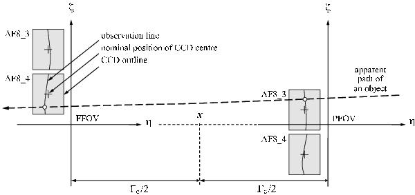
Schematic illustration of how the field angles (η,ζ) are defined in terms of the CCD layout in Fig. 3. For simplicity only the projections of two CCDs, AF8_3 and AF8_4, into the Scanning Reference System (SRS) are shown (not to scale). The field angles have their origins at the respective viewing direction fP or fF (Fig. 2), which are defined in relation to the nominal centres of the CCDs (crosses); the actual configuration of the detectors is described by fiducial observation lines according to Eq. (15). The dashed curve shows the apparent path of a stellar image across the two fields of view. Its intersections with the observation lines define the instants of observations.
Current usage metrics show cumulative count of Article Views (full-text article views including HTML views, PDF and ePub downloads, according to the available data) and Abstracts Views on Vision4Press platform.
Data correspond to usage on the plateform after 2015. The current usage metrics is available 48-96 hours after online publication and is updated daily on week days.
Initial download of the metrics may take a while.