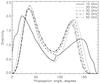
Fig. 8
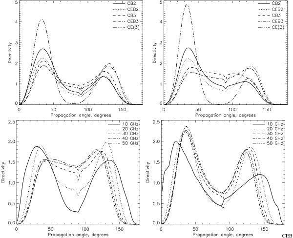
Upper plots: directivity of the integrated MW emission spectra (Eq. (9) with the intensity from Eq. (10)) versus different propagation directions (see note in Fig. 7) simulated for the models CB, CE, and CEB (indicated on the plots) with convergence factors 2 and 3 for 20 GHz (left plot) and 30 GHz (right plot). Bottom plots: MW directivity versus propagation directions calculated for different frequencies (indicated on the plots) with CEB3 model (left plot) and CEB2 model (right plot). CE(3) indicates the MW emission calculated for the distribution functions with CE model, but with the magnetic field magnitudes at relevant depths corresponding to CEB3.
Current usage metrics show cumulative count of Article Views (full-text article views including HTML views, PDF and ePub downloads, according to the available data) and Abstracts Views on Vision4Press platform.
Data correspond to usage on the plateform after 2015. The current usage metrics is available 48-96 hours after online publication and is updated daily on week days.
Initial download of the metrics may take a while.