| Issue |
A&A
Volume 517, July 2010
|
|
|---|---|---|
| Article Number | A27 | |
| Number of page(s) | 19 | |
| Section | Extragalactic astronomy | |
| DOI | https://doi.org/10.1051/0004-6361/201014154 | |
| Published online | 28 July 2010 | |
A study of the interplay between ionized gas and star clusters in the central
region of NGC 5253 with 2D spectroscopy![[*]](/icons/foot_motif.png)
A. Monreal-Ibero1 - J. M. Vílchez2 - J. R. Walsh1 - C. Muñoz-Tuñón3
1 - European Organisation for Astronomical Research
in the Southern Hemisphere, Karl-Schwarzschild-Strasse 2, 85748
Garching bei München, Germany
2 -
Instituto de Astrofísica de Andalucía (CSIC), C/ Camino Bajo de Huétor 50, 18008 Granada, Spain
3 -
Instituto de Astrofísica de Canarias, C/ vía Láctea, s/n, 38205 La Laguna, Spain
Received 28 January 2010 / Accepted 24 March 2010
Abstract
Context. Starbursts are one of the main contributors to the
chemical enrichment of the interstellar medium. However, mechanisms
governing the interaction between the recent star formation and the
surrounding gas are not fully understood. Because of their
a priori simplicity, the subgroup of H II galaxies constitute an ideal sample to study these mechanisms.
Aims. A detailed 2D study of the central region of NGC 5253
has been performed to characterize the stellar and ionized gas
structure as well as the extinction distribution, physical properties
and kinematics of the ionized gas in the central ![]() 210 pc
210 pc ![]() 130 pc.
130 pc.
Methods. We utilized optical integral field spectroscopy (IFS) data obtained with FLAMES.
Results. A detailed extinction map for the ionized gas in
NGC 5253 shows that the largest extinction is associated
with the prominent Giant H II region. There is an offset of ![]() 0
0
![]() 5
between the peak of the optical continuum and the extinction peak in
agreement with findings in the infrared. We found that stars suffer
less extinction than gas by a factor of
5
between the peak of the optical continuum and the extinction peak in
agreement with findings in the infrared. We found that stars suffer
less extinction than gas by a factor of ![]() 0.33. The [S II]
0.33. The [S II]![]() 6717/[S II]
6717/[S II]![]() 6731 map shows an electron density (
6731 map shows an electron density (![]() )
gradient declining from the peak of emission in H
)
gradient declining from the peak of emission in H![]() (790 cm-3) outwards, while the argon line ratio traces areas with
(790 cm-3) outwards, while the argon line ratio traces areas with
![]() cm-3. The area polluted with extra nitrogen, as deduced from the excess [N II]
cm-3. The area polluted with extra nitrogen, as deduced from the excess [N II]![]() 6584/H
6584/H![]() ,
extends up to distances of 3
,
extends up to distances of 3
![]() 3 (
3 (![]() 60 pc) from the maximum pollution, which is offset by
60 pc) from the maximum pollution, which is offset by ![]() 1
1
![]() 5 from the peak of continuum emission. Wolf-Rayet features are distributed in an irregular pattern over a larger area (
5 from the peak of continuum emission. Wolf-Rayet features are distributed in an irregular pattern over a larger area (![]() pc
pc ![]() 100 pc) and associated with young stellar clusters. We measured He+ abundances over most of the field of view and values of He++/H+
100 pc) and associated with young stellar clusters. We measured He+ abundances over most of the field of view and values of He++/H+ ![]() 0.0005
in localized areas which do not coincide, in general, with the
areas presenting W-R emission or extra nitrogen. The line profiles
are complex. Up to three emission components were needed to
reproduce them. One of them, associated with the giant H II region, presents supersonic widths and [N II]
0.0005
in localized areas which do not coincide, in general, with the
areas presenting W-R emission or extra nitrogen. The line profiles
are complex. Up to three emission components were needed to
reproduce them. One of them, associated with the giant H II region, presents supersonic widths and [N II]![]() 6584 and [S II]
6584 and [S II]
![]() 6717,6731 emission lines shifted up to 40 km s-1 with respect to H
6717,6731 emission lines shifted up to 40 km s-1 with respect to H![]() .
Similarly, one of the narrow components presents offsets in the [N II]
.
Similarly, one of the narrow components presents offsets in the [N II]![]() 6584 line of
6584 line of
![]() km s-1.
This is the first time that maps with such velocity offsets for a
starburst galaxy have been presented. The observables in the giant H II region
fit with a scenario where the two super stellar clusters (SSCs) produce
an outflow that encounters the previously quiescent gas. The south-west
part of the FLAMES IFU field is consistent with a more evolved
stage where the star clusters have already cleared out their local
environment.
km s-1.
This is the first time that maps with such velocity offsets for a
starburst galaxy have been presented. The observables in the giant H II region
fit with a scenario where the two super stellar clusters (SSCs) produce
an outflow that encounters the previously quiescent gas. The south-west
part of the FLAMES IFU field is consistent with a more evolved
stage where the star clusters have already cleared out their local
environment.
Key words: galaxies: starburst - galaxies: dwarf - galaxies: individual: NGC 5253 - galaxies: ISM - galaxies: abundances - galaxies: kinematics and dynamics
1 Introduction
Starbursts are events characterized by star-formation rates much higher than those found in gas-rich normal galaxies. They are considered one of the main contributors to the chemical enrichment of the interstellar medium (ISM) and can be found in galaxies covering a wide range of masses, luminosities, metallicities and interaction stages such as blue compact dwarfs, nuclei of spiral galaxies, or (Ultra)luminous Infrared Galaxies (see Conti et al. 2008, and references therein).
A particularly interesting subset are the H II galaxies, identified for the first time by Haro (1956): gas-rich, metal poor (
![]() )
dwarf systems characterized by the presence of large ionized H II regions that dominate their optical spectra (see Kunth & Östlin 2000,
for a review of these galaxies). These systems are a priori
simple, which makes them the ideal laboratories to test the interplay
between massive star formation and the ISM.
)
dwarf systems characterized by the presence of large ionized H II regions that dominate their optical spectra (see Kunth & Östlin 2000,
for a review of these galaxies). These systems are a priori
simple, which makes them the ideal laboratories to test the interplay
between massive star formation and the ISM.
NGC 5253, an irregular galaxy located in the Centarus A/M 83 galaxy complex (Karachentsev et al. 2007), is a local example of an H II galaxy. This galaxy is suffering a burst of star formation which is believed to have been triggered by an encounter with M 83 (van den Bergh 1980). This is supported by the existence of the H I plume extending along the optical minor axis which is best explained as tidal debris (Kobulnicky & Skillman 2008).
NGC 5253 constitutes an optimal target for the study of the starburst phenomenon. On the one hand, its proximity allows a linear spatial resolution to be achieved that is good enough to study the details of the interplay between the different components (i.e. gas, dust and star clusters) in the central region. On the other hand, this system has been observed in practically all spectral ranges from the X-ray to the radio, and therefore a large amount of ancillary information is available.
The basic characteristics of this galaxy are compiled in Table 1. Its stellar content has been widely studied and more than 300 stellar clusters have been detected (Cresci et al. 2005).
Multi-band photometry with the WFPC2 has revealed that those in its central region present typical masses of
![]()
![]()
![]() and are very young, with ages of
and are very young, with ages of
![]() Myr (e.g. Harris et al. 2004). In particular, HST-NICMOS images have revealed that the
nucleus of the galaxy is made out of two very massive (
Myr (e.g. Harris et al. 2004). In particular, HST-NICMOS images have revealed that the
nucleus of the galaxy is made out of two very massive (
![]()
![]()
![]() )
super stellar clusters (SSCs), with ages of about
)
super stellar clusters (SSCs), with ages of about ![]() Myr, separated by
Myr, separated by
![]() (Alonso-Herrero et al. 2004), and which are coincident with the double radio nebula detected at 1.3 cm (Turner et al. 2000).
Also, detection of spectral features characteristic of Wolf-Rayet (W-R)
stars in specific regions of the galaxy have been reported (e.g. Schaerer et al. 1997). Recently, seven supernova
remnants have been detected in the central region of this galaxy by means of the [Fe II]
(Alonso-Herrero et al. 2004), and which are coincident with the double radio nebula detected at 1.3 cm (Turner et al. 2000).
Also, detection of spectral features characteristic of Wolf-Rayet (W-R)
stars in specific regions of the galaxy have been reported (e.g. Schaerer et al. 1997). Recently, seven supernova
remnants have been detected in the central region of this galaxy by means of the [Fe II]![]() 1.644
1.644 ![]() m emission (Labrie & Pritchet 2006).
m emission (Labrie & Pritchet 2006).
NGC 5253 presents a filamentary structure in H![]() (e.g. Martin 1998)
associated with extended diffuse emission in X-ray which can be
explained as multiple superbubbles around its OBs associations and
SSCs that are the results of the combined action of stellar winds and
supernovae (Summers et al. 2004; Strickland & Stevens 1999).
(e.g. Martin 1998)
associated with extended diffuse emission in X-ray which can be
explained as multiple superbubbles around its OBs associations and
SSCs that are the results of the combined action of stellar winds and
supernovae (Summers et al. 2004; Strickland & Stevens 1999).
Table 1: Basic data for NGC 5253.
The measured metallicity of this galaxy is relatively low (see Table 1)
and presents a generally uniform distribution. However,
an increase in the abundance of nitrogen in the central region
of
![]() times the mean has been reported (Walsh & Roy 1989; López-Sánchez et al. 2007; Kobulnicky et al. 1997).
No other elemental species appears to present spatial abundance
fluctuations. The reason for this nitrogen enhancement has not
been fully clarified yet although a connection with the
W-R population has been suggested.
times the mean has been reported (Walsh & Roy 1989; López-Sánchez et al. 2007; Kobulnicky et al. 1997).
No other elemental species appears to present spatial abundance
fluctuations. The reason for this nitrogen enhancement has not
been fully clarified yet although a connection with the
W-R population has been suggested.
On account of their irregular structure, a proper characterization of the physical properties of H II galaxies, necessary to explore the interplay of mechanisms acting between gas and stars, requires high quality two-dimensional spectral information able to produce a continuous mapping of the relevant quantities. Such observations have traditionally been done in the optical and near-infrared by mapping the galaxy under study with a long-slit (e.g. Walsh & Roy 1989; Vílchez & Iglesias-Páramo 1998). This is, however, expensive in terms of telescope time and might be affected by some technical problems such as misalignment of the slit or changes in the observing conditions with time. The advent and popularization of integral field spectroscopy (IFS) facilities, able to record simultaneously the spectra of an extended continuous field, overcomes these difficulties. Nevertheless, work based on this technique devoted to the study of H II galaxies is still relatively rare (e.g. Bordalo et al. 2009; Lagos et al. 2009; James et al. 2009; Izotov et al. 2006; Kehrig et al. 2008; García-Lorenzo et al. 2008).
Here, we present IFS observations of the central area of NGC 5253 in order to study the mechanisms that govern the interaction between the young stars and the surrounding ionized gas. The paper is organized as follows: Sect. 2 contains the observational and technical details regarding the data reduction and derivation of the required observables; Sect. 3 describes the stellar and ionized gas structure as well as the extinction distribution and the physical and kinematic properties of the ionized gas; Sect. 4 discusses the evolutionary stage of the gas surrounding the stellar clusters, focusing on the two most relevant areas of the field of view (f.o.v.). Section 5 itemises our results and conclusions.
2 Observations, data reduction and line fitting
2.1 Observations
Data were obtained with the Fibre Large Array Multi Element Spectrograph, FLAMES (Pasquini et al. 2002)
at Kueyen, Telescope Unit 2 of the 8 m VLT at ESO's
observatory on Paranal, on February 10, 2007. The central
region of the galaxy was observed with the ARGUS Integral Field Unit
(IFU) which has a field of view of
![]()
![]()
![]() with a sampling of 0.52
with a sampling of 0.52
![]() /lens.
In addition, ARGUS has 15 fibers that can simultaneously
observe the sky and which were arranged forming a circle around the
IFU. The precise covered area is shown in Fig. 1 which contains the FLAMES field of view over-plotted on an HST B, H
/lens.
In addition, ARGUS has 15 fibers that can simultaneously
observe the sky and which were arranged forming a circle around the
IFU. The precise covered area is shown in Fig. 1 which contains the FLAMES field of view over-plotted on an HST B, H![]() ,
I colour image.
,
I colour image.
We utilized two different gratings in order to obtain information for
the most important emission lines in the optical spectral range. Data
were taken under photometric conditions and seeing ranged typically
between
![]() and
and
![]() .
The covered spectral range, resolving power, exposure time and airmass for each configuration are shown in Table 2.
In addition
to the science frames, continuum and ThAr arc lamps exposures
as well as frames for the spectrophotometric standard star
CD-32 9927 were obtained.
.
The covered spectral range, resolving power, exposure time and airmass for each configuration are shown in Table 2.
In addition
to the science frames, continuum and ThAr arc lamps exposures
as well as frames for the spectrophotometric standard star
CD-32 9927 were obtained.
2.2 Data reduction
The basic reduction steps for the FLAMES data were performed with a
combination of the pipeline provided by ESO (version 1.0)![]() via esorex, version 2.0.2 and some IRAF
via esorex, version 2.0.2 and some IRAF![]() routines. First of all we masked a bad column in the raw data using the task fixpix
within IRAF. Then, each individual frame was processed using the
ESO pipeline in order to perform bias subtraction, spectral
tracing and extraction, wavelength calibration and correction of fibre
transmission.
routines. First of all we masked a bad column in the raw data using the task fixpix
within IRAF. Then, each individual frame was processed using the
ESO pipeline in order to perform bias subtraction, spectral
tracing and extraction, wavelength calibration and correction of fibre
transmission.
Uncertainties in the relative wavelength calibration were estimated by
fitting a Gaussian to three isolated lines in every spectrum of
the arc exposure. The standard deviation of the central wavelength
for a certain line gives an idea of the associated error in that
spectral range. We were able to determine the centroid of the lines
with an uncertainty of ![]() 0.005 Å, which translates into velocities of
0.005 Å, which translates into velocities of ![]() 0.3 km s-1. The spectral resolution was very uniform over the whole field-of-view with values of 0.178
0.3 km s-1. The spectral resolution was very uniform over the whole field-of-view with values of 0.178 ![]() 0.004 Å and 0.241
0.004 Å and 0.241 ![]() 0.009 Å, FWHM for the blue and red configuration respectively, which translates into
0.009 Å, FWHM for the blue and red configuration respectively, which translates into
![]()
![]() 4.7 km s-1.
4.7 km s-1.
For the sky subtraction, we created a good signal-to-noise (S/N)
spectrum by averaging the spectra of the sky fibres in each individual
frame. This sky spectrum was subsequently subtracted from every
spectrum. In several of the sky fibres, the strongest emission
lines, namely [O III]![]() 5007 in the blue
frames and H
5007 in the blue
frames and H![]() in the red frames, could clearly be detected. We attributed this effect
to some cross-talk from the adjacent fibers. A direct comparison
of the flux in the sky and adjacent fibers showed that this
contribution was always
in the red frames, could clearly be detected. We attributed this effect
to some cross-talk from the adjacent fibers. A direct comparison
of the flux in the sky and adjacent fibers showed that this
contribution was always ![]() 0.6%
which is negligible in terms of sky subtraction. However, in order
to reduce this contamination to a minimum, we decided not to use these
fibres in the creation of the high S/N sky spectra.
0.6%
which is negligible in terms of sky subtraction. However, in order
to reduce this contamination to a minimum, we decided not to use these
fibres in the creation of the high S/N sky spectra.
![\begin{figure}
\par\includegraphics[width=8.5cm,clip]{14154fg1.ps}
\end{figure}](/articles/aa/full_html/2010/09/aa14154-10/img58.png)
|
Figure 1:
False colour image in filters F435W (B, blue), F658N (
|
| Open with DEXTER | |
Table 2: Observation log.
Regarding the flux calibration, a spectrum for the calibration star was created by co-adding all the fibers of the standard star frames. Then, a sensitivity function was determined with the IRAF tasks standard and sensfunc and science frames were calibrated with calibrate. Afterwards, frames corresponding to each configuration were combined and cosmic rays rejected with the task imcombine. As a last step, the data were reformatted into two easier-to-use data cubes, with two spatial and one spectral dimension, using the known position of the lenses within the array.
2.3 Line fitting and map creation
In order to obtain the relevant emission line information, line
profiles were fitted using Gaussian functions. This procedure was done
in a semi-automatic way using the IDL based routine MPFITEXPR![]() (Markwardt 2009)
which offers ample flexibility in case constraints on the parameters of
the fit are included, such as lines in fixed ratio. The procedure was
as follows.
(Markwardt 2009)
which offers ample flexibility in case constraints on the parameters of
the fit are included, such as lines in fixed ratio. The procedure was
as follows.
As a first step, we fit all the lines by a single Gaussian. The H![]() +[N II] complex
was fitted simultaneously by one Gaussian per emission line plus a flat
continuum first-degree
polynomial using a common width for the three lines and fixing the
separation in wavelength between the lines according to the redshift
provided at NED
+[N II] complex
was fitted simultaneously by one Gaussian per emission line plus a flat
continuum first-degree
polynomial using a common width for the three lines and fixing the
separation in wavelength between the lines according to the redshift
provided at NED![]() and the nitrogen line ratio (
and the nitrogen line ratio (![]() 6583/
6583/![]() 6548) to 3. The same procedure was repeated for the [S II]
6548) to 3. The same procedure was repeated for the [S II]
![]() 6717, 6730 doublet, the [Ar IV]
6717, 6730 doublet, the [Ar IV]![]() 4711 line (which was fitted jointly with the [Fe III]
4711 line (which was fitted jointly with the [Fe III]![]() 4701 and He I
4701 and He I![]() 4713) and the [Ar IV]
4713) and the [Ar IV]![]() 4740 line (which was fitted jointly with the [Fe III]
4740 line (which was fitted jointly with the [Fe III]![]() 4734 line), but this time without any restriction on the line ratios. Finally, H
4734 line), but this time without any restriction on the line ratios. Finally, H![]() ,
[O III]
,
[O III]![]() 5007, and He I
5007, and He I![]() 6678 were individually fitted.
6678 were individually fitted.
This single Gaussian fit gave a good measurement for the line fluxes
and the results of these fits are the used in all the forthcoming
analysis, with the exception of the kinematics. This latter analysis
requires a more complex line fitting scheme, since several lines showed
signs of asymmetries and/or multiple components in their profiles for a
large number of spaxels. In those
cases, multi-component fits were performed. Over the whole field
of view we compared the measured flux from performing the fit with a
single Gaussian to the fit by several components in the brightest
emission lines (namely: H![]() ,
[O III]
,
[O III]![]() 5007, H
5007, H![]() ,
[N II]
,
[N II]![]() 6584 and [S II]
6584 and [S II]
![]() 6717,6731).
Differences between the two sets of line fluxes ranged typically
from 0% to 15%, depending on the spaxel and the emission
line, and translated into differences in the line ratios
6717,6731).
Differences between the two sets of line fluxes ranged typically
from 0% to 15%, depending on the spaxel and the emission
line, and translated into differences in the line ratios ![]() 0.06 dex.
0.06 dex.
In all the cases, MPFITEXPR estimated an error for the fit using the standard deviation of the adjacent continuum. Those fits with a ratio between line flux and error less than three were automatically rejected. The remaining spectra were visually inspected and classified as good or bad fits.
Finally, for each of the observables, we used the derived quantity together with the position within the data-cube for each spaxel to create an image suitable to be manipulated with standard astronomical software. Hereafter, we will use both terms, map and image, when referring to these.
3 Results
3.1 Stellar and ionized gas structure
Figure 2 displays the stellar structure, as traced by a continuum close to H![]() ,
as well as the one for the ionized gas (traced by the H
,
as well as the one for the ionized gas (traced by the H![]() emission line). The over-plotted contours, which represent the HST-ACS images in the F659N and F814W bands
convolved with a Gaussian to match the seeing at Paranal, show
good correspondence between the images created from the IFS data
and the HST images (although obviously with poorer resolution for
the ground-based
FLAMES data). A direct comparison of these maps shows how the
stellar and ionized gas structure differs.
emission line). The over-plotted contours, which represent the HST-ACS images in the F659N and F814W bands
convolved with a Gaussian to match the seeing at Paranal, show
good correspondence between the images created from the IFS data
and the HST images (although obviously with poorer resolution for
the ground-based
FLAMES data). A direct comparison of these maps shows how the
stellar and ionized gas structure differs.
![\begin{figure}
\par\includegraphics[width=8cm,clip]{14154fg2a.ps}\par\includegraphics[width=8cm,clip]{14154fg2b.ps}
\end{figure}](/articles/aa/full_html/2010/09/aa14154-10/img61.png)
|
Figure 2:
Top: stellar component distribution as traced by a continuum map made from the average flux in the spectral range
6525-6545 Å and
6600-6620 Å. Bottom: ionized gas distribution as traced by the H |
| Open with DEXTER | |
Table 3: Main reference clusters.
The continuum image displays three main peaks of emission which will be
used through the paper as reference. We have associated each of these
peaks with one or more star clusters by direct comparison with
ACS images. Table 3
compiles their positions within the FLAMES field of view together with
the names of the corresponding clusters according to several reference
works. These clusters trace a sequence in age as we move towards the
right (south-west) in the FLAMES field of view. The clusters associated
with peak #1 are very young (
![]() Myr, Alonso-Herrero et al. 2004; Harris et al. 2004), those associated with peak #2 display a range of ages from very young to intermediate age (
Myr, Alonso-Herrero et al. 2004; Harris et al. 2004), those associated with peak #2 display a range of ages from very young to intermediate age (
![]() Myr, Harris et al. 2004), while the stars in the pair of clusters associated with peak #3 seem to have intermediate ages (70-113 Myr, Harris et al. 2004).
Myr, Harris et al. 2004), while the stars in the pair of clusters associated with peak #3 seem to have intermediate ages (70-113 Myr, Harris et al. 2004).
The H![]() emission line reproduces the structure described by Calzetti et al. (1997)
using an HST WFPC2 image. Briefly, the central region of
NGC 5253 is divided into two parts by a dust lane that crosses the
galaxy along the east-west direction (from
emission line reproduces the structure described by Calzetti et al. (1997)
using an HST WFPC2 image. Briefly, the central region of
NGC 5253 is divided into two parts by a dust lane that crosses the
galaxy along the east-west direction (from ![]() [2
[2
![]() 0, -3
0, -3
![]() 0]
0]![]() to the Complex #3). Most of the H
to the Complex #3). Most of the H![]() emission is located towards the north of this lane where there is giant H II region
associated with the Complex #1. This region shows two
tongue-shaped extensions towards the upper and lower part of the
FLAMES field of view (PA on the sky of
emission is located towards the north of this lane where there is giant H II region
associated with the Complex #1. This region shows two
tongue-shaped extensions towards the upper and lower part of the
FLAMES field of view (PA on the sky of
![]() and
and
![]() ,
respectively) as well as a extension at PA
,
respectively) as well as a extension at PA ![]()
![]() which contains the Complex #2. Towards the south of the dust lane, the emission is dominated by a peak at
which contains the Complex #2. Towards the south of the dust lane, the emission is dominated by a peak at ![]() [-3
[-3
![]() 5, -2
5, -2
![]() 5] which could be associated with cluster 17 in Harris et al. (2004).
5] which could be associated with cluster 17 in Harris et al. (2004).
3.2 Extinction structure
Extinction was derived assuming an intrinsic Balmer emission line ratio of H![]() /H
/H![]() = 2.87 (Osterbrock & Ferland 2006, for an
= 2.87 (Osterbrock & Ferland 2006, for an
![]() K) and using the extinction curve of Fluks et al. (1994). Since the H
K) and using the extinction curve of Fluks et al. (1994). Since the H![]() and H
and H![]() emission lines are separated by
emission lines are separated by ![]() 1700 Å
and both of them had high signal-to-noise ratio in only a single
exposure, we decided to obtain the extinction maps from the LR3 and
LR6 exposures observed at the smallest airmass
(1.009 and 1.160, respectively), thus minimizing any effect
due to differential atmospheric refraction.
1700 Å
and both of them had high signal-to-noise ratio in only a single
exposure, we decided to obtain the extinction maps from the LR3 and
LR6 exposures observed at the smallest airmass
(1.009 and 1.160, respectively), thus minimizing any effect
due to differential atmospheric refraction.
We have not included any correction for an underlying stellar
population. We inspected carefully each individual spectrum to look for
the presence of the stellar absorption feature in H![]() .
Only in those spaxels associated with the area around the Complex #3 (
.
Only in those spaxels associated with the area around the Complex #3 (![]() 9-10 spaxels or
9-10 spaxels or ![]() 1
1
![]() 5
5 ![]() 1
1
![]() 5
in total) was such an absorption detected. We estimated the
influence of this component by fitting both the absorption and the
emission component in the most
affected spaxel. Equivalent widths were
5
in total) was such an absorption detected. We estimated the
influence of this component by fitting both the absorption and the
emission component in the most
affected spaxel. Equivalent widths were ![]() 3 and
3 and ![]() 9 Å, respectively. In these spaxels, the absorption line was typically
9 Å, respectively. In these spaxels, the absorption line was typically
![]() times wider and with about half - one third of the flux of the emission line. This implies an underestimation of H
times wider and with about half - one third of the flux of the emission line. This implies an underestimation of H![]() emission
line flux of about 10%. For the particular area around
Complex #3, this translates into a real extinction of
emission
line flux of about 10%. For the particular area around
Complex #3, this translates into a real extinction of
![]() mag instead of the measured
mag instead of the measured
![]() mag.
mag.
The corresponding reddening map was determined assuming E(B-V) = AV / 3.1 (Rieke & Lebofsky 1985) and is presented in Fig. 3. This map shows that the extinction is distributed in a non-uniform manner ranging from E(B-V) = 0.16 to 0.64 (mean 0.33, standard deviation, 0.07). Given that Galactic reddening for NGC 5253 is 0.056 (Schlegel et al. 1998), nearly all of the extinction can be considered intrinsic to the galaxy.
In general terms, the structure presented in this map coincides with the one presented by Calzetti et al. (1997). The dust lane mentioned in the previous section is clearly visible here and it causes extinction of AV ![]() 0.10-1.13 mag. However, the larger measured extinction values are associated with the giant H II region, in agreement with the H I distribution (Kobulnicky & Skillman 2008). Dust in this area forms an S-shaped distribution with
0.10-1.13 mag. However, the larger measured extinction values are associated with the giant H II region, in agreement with the H I distribution (Kobulnicky & Skillman 2008). Dust in this area forms an S-shaped distribution with
![]() mag in the arms.
mag in the arms.
![\begin{figure}
\par\includegraphics[width=8cm,clip]{14154fg3.ps}
\end{figure}](/articles/aa/full_html/2010/09/aa14154-10/img72.png)
|
Figure 3:
Reddening map obtained from the hydrogen recombination lines assuming H |
| Open with DEXTER | |
In order to explore the relation between the extinction suffered by the gas and by the stellar populations, our E(B-V) measurements
were compared with colours defined ad hoc. For the covered
spectral range, it is not possible to exactly simulate any of the
existing standard filters. It is possible, however, to create
filters relatively similar to the
![]() and
and ![]() ones. We have simulated two set of filters.
ones. We have simulated two set of filters.
In the first case, the flux was integrated over two large
wavelength ranges (465-495 nm and 643-673 nm) in order to
simulate broad filters. The relation between the reddening derived for
the ionized gas and the derived colour, hereafter
![]() ,
is shown in the upper panel of Fig. 4,
as would be observed with photometry. The first order polynomial
fit to the data and the Pearson correlation coefficient are included on
the plot. Also shown is the expected relation for an Im galaxy
with foreground reddening. This latter was derived for the average of
two Im templates (NGC 4449 and NGC 4485) from Kennicutt (1992) applying a foreground screen of dust with a standard Galactic reddening law (Cardelli et al. 1989) with R=3.1.
There is a strong difference between the expected relation for a
foreground screen of dust and the measured values. On the one hand,
colours are much redder. On the other hand, the slope of the
1-degree polynomial fit is much less steep than the expected one.
Also, there is a very good correlation between the E(B-V) and our synthetic
,
is shown in the upper panel of Fig. 4,
as would be observed with photometry. The first order polynomial
fit to the data and the Pearson correlation coefficient are included on
the plot. Also shown is the expected relation for an Im galaxy
with foreground reddening. This latter was derived for the average of
two Im templates (NGC 4449 and NGC 4485) from Kennicutt (1992) applying a foreground screen of dust with a standard Galactic reddening law (Cardelli et al. 1989) with R=3.1.
There is a strong difference between the expected relation for a
foreground screen of dust and the measured values. On the one hand,
colours are much redder. On the other hand, the slope of the
1-degree polynomial fit is much less steep than the expected one.
Also, there is a very good correlation between the E(B-V) and our synthetic
![]() colour. All this can be attributed to the contamination of the gas emission lines, mainly H
colour. All this can be attributed to the contamination of the gas emission lines, mainly H![]() and H
and H![]() ,
in our filters.
,
in our filters.
![\begin{figure}
\par\includegraphics[width=7.5cm,clip]{14154fg4a.ps}\par\includegraphics[width=7.5cm,clip]{14154fg4b.ps}
\end{figure}](/articles/aa/full_html/2010/09/aa14154-10/img77.png)
|
Figure 4:
Relation between the derived reddening and a colour similar to
|
| Open with DEXTER | |
![\begin{figure}
\par\includegraphics[width=8cm,clip]{14154fg5.ps}
\end{figure}](/articles/aa/full_html/2010/09/aa14154-10/img78.png)
|
Figure 5: Line free colour map. The simulated filters have been defined as explained in Fig. 4. The position of the three main peaks of continuum emission are shown for reference. |
| Open with DEXTER | |
In the second set, we restricted the spectral ranges for the simulated
filters to a narrower wavelength range which was free from the
contamination of the main emission lines. The map for this line-free
colour is displayed in Fig. 5. The structure resembles the one presented in Fig. 3 (i.e. dust lane, redder colours associated with the giant H II region),
although there are differences, that can be attributed to differences
in the properties of the stellar populations in the different clusters.
The relation between the reddening and the corresponding
![]() is shown in the lower panel of Fig. 4.
This time colours are more similar to what is expected for a given
stellar population suffering a certain amount of extinction. However,
for a given colour, stars do not reach the expected reddening
if gas and stars were suffering the same extinction (i.e. data
points are below the green line). The ratio between the slopes indicates that extinction in the stars is
a factor 0.33 lower than the one for the ionized gas. This is similar to what Calzetti et al. (1997)
found using HST images who estimated that the extinction suffered
by the stars is a factor 0.5 lower than for the ionized gas and
can be explained if the dust has a larger covering factor for the
ionized gas than for the stars (Calzetti et al. 1994).
is shown in the lower panel of Fig. 4.
This time colours are more similar to what is expected for a given
stellar population suffering a certain amount of extinction. However,
for a given colour, stars do not reach the expected reddening
if gas and stars were suffering the same extinction (i.e. data
points are below the green line). The ratio between the slopes indicates that extinction in the stars is
a factor 0.33 lower than the one for the ionized gas. This is similar to what Calzetti et al. (1997)
found using HST images who estimated that the extinction suffered
by the stars is a factor 0.5 lower than for the ionized gas and
can be explained if the dust has a larger covering factor for the
ionized gas than for the stars (Calzetti et al. 1994).
In general, our E(B-V) measurements agree with previous ones using the same emission lines in specific areas (e.g. López-Sánchez et al. 2007; González-Riestra et al. 1987) or with poorer spatial resolution (Walsh & Roy 1989).
However there are discrepancies when comparing with the estimation of
the extinction at other wavelengths. In particular, the peak
of extinction (AV = 2.1 mag, according to the Balmer line ratio) is offset by
![]() from the peak of continuum emission. Alonso-Herrero et al. (2004)
showed how in the central area of NGC 5253 there are two massive
star clusters, C1 and C2. While C1 is the dominant
source in the optical, coincident with our peak in the continuum map,
the more massive and extinguished C2 is the dominant source in the
infrared. The contours for the NICMOS
from the peak of continuum emission. Alonso-Herrero et al. (2004)
showed how in the central area of NGC 5253 there are two massive
star clusters, C1 and C2. While C1 is the dominant
source in the optical, coincident with our peak in the continuum map,
the more massive and extinguished C2 is the dominant source in the
infrared. The contours for the NICMOS ![]() image in Fig. 3
show the good correspondence between our maximum of extinction
and C2. Measurements in the near and mid-infrared suggest
extinctions of
image in Fig. 3
show the good correspondence between our maximum of extinction
and C2. Measurements in the near and mid-infrared suggest
extinctions of
![]() mag for this cluster (Martín-Hernández et al. 2005; Turner et al. 2003; Alonso-Herrero et al. 2004).
The discrepancy between these two values indicates that a foreground
screen model is not the appropriate one to explain the distribution of
the dust in the giant H II region.
mag for this cluster (Martín-Hernández et al. 2005; Turner et al. 2003; Alonso-Herrero et al. 2004).
The discrepancy between these two values indicates that a foreground
screen model is not the appropriate one to explain the distribution of
the dust in the giant H II region.
3.3 Electron density distribution
Electron density (![]() )
can be determined from the [S II]
)
can be determined from the [S II]![]() 6717/ [S II]
6717/ [S II]![]() 6731 and [Ar IV]
6731 and [Ar IV]![]() 4711/[Ar IV]
4711/[Ar IV]![]() 4740 line
ratios; values of 1.25 and 1.00 respectively were measured in
a spectrum made from the sum of all our spaxels. Hereafter, we will
refer to this spectrum as the integrated spectrum. Electron densities were determined assuming an electron temperature of 11 650 K, the average of the values given in López-Sánchez et al. (2007), and using the task temden, based on the fivel program (Shaw & Dufour 1995) included in the IRAF package nebular. Derived values of
4740 line
ratios; values of 1.25 and 1.00 respectively were measured in
a spectrum made from the sum of all our spaxels. Hereafter, we will
refer to this spectrum as the integrated spectrum. Electron densities were determined assuming an electron temperature of 11 650 K, the average of the values given in López-Sánchez et al. (2007), and using the task temden, based on the fivel program (Shaw & Dufour 1995) included in the IRAF package nebular. Derived values of ![]() for the two line ratios were 180 cm-3 and 4520 cm-3,
respectively. Differences between the electron densities derived from
the argon and sulphur lines are usually found in ionized gaseous
nebulae (see Wang et al. 2004) and are understood in terms of the ionization structure of the nebulae under study: [Ar IV] lines normally come from inner regions of higher ionization degree than [S II] lines. Typically, for giant Galactic and extragalactic H II regions, derived
for the two line ratios were 180 cm-3 and 4520 cm-3,
respectively. Differences between the electron densities derived from
the argon and sulphur lines are usually found in ionized gaseous
nebulae (see Wang et al. 2004) and are understood in terms of the ionization structure of the nebulae under study: [Ar IV] lines normally come from inner regions of higher ionization degree than [S II] lines. Typically, for giant Galactic and extragalactic H II regions, derived ![]() from these two line ratios differ in a factor of
from these two line ratios differ in a factor of ![]() 5 (e.g. Tsamis et al. 2003; Esteban et al. 2002) which is much lower than what we find for the integrated spectrum of NGC 5253 (
5 (e.g. Tsamis et al. 2003; Esteban et al. 2002) which is much lower than what we find for the integrated spectrum of NGC 5253 (![]() 25). However, when only the giant H II region is taken into account (i.e. the area of
25). However, when only the giant H II region is taken into account (i.e. the area of ![]() 90 spaxels
where the argon lines are detected) the difference between the
densities derived from the argon and the sulphur lines (
90 spaxels
where the argon lines are detected) the difference between the
densities derived from the argon and the sulphur lines (![]() 10, see typical values for the densities below) is more similar to those found for other H II regions.
10, see typical values for the densities below) is more similar to those found for other H II regions.
Maps for both ratios are shown in Fig. 6.
According to the sulphur line ratio - detected over the whole
field - densities range from very low values, of the order of
the low density limit, in a region of about
![]()
![]()
![]() in the upper right corner of the field just above the Complex #3, to 790 cm -3 at the peak of the emission in the cluster associated with the H II region, with a mean (median) over the field of view of
in the upper right corner of the field just above the Complex #3, to 790 cm -3 at the peak of the emission in the cluster associated with the H II region, with a mean (median) over the field of view of
![]() cm-3. The rest of the H II regions still present high densities (of about 400 cm-3 as a whole, 480 cm-3 in the H II-2, (i.e. the upper area of the giant H II region, Kobulnicky et al. 1997). This agrees well with the value estimated from long-slit measurements (López-Sánchez et al. 2007). The tail and the region associated with the cluster UV-1 present intermediate values (of about 200 cm-3).
cm-3. The rest of the H II regions still present high densities (of about 400 cm-3 as a whole, 480 cm-3 in the H II-2, (i.e. the upper area of the giant H II region, Kobulnicky et al. 1997). This agrees well with the value estimated from long-slit measurements (López-Sánchez et al. 2007). The tail and the region associated with the cluster UV-1 present intermediate values (of about 200 cm-3).
![\begin{figure}
\par\includegraphics[width=8cm,clip]{14154fg6a.ps}\vspace*{3mm}
\includegraphics[width=8cm,clip]{14154fg6b.ps}
\end{figure}](/articles/aa/full_html/2010/09/aa14154-10/img85.png)
|
Figure 6: Maps for the line ratios sensitive to the electron density. The position of the three main peaks of continuum emission are shown as crosses for reference. The displayed ranges in the line ratios imply electron densities of <10-790 cm-3 and 190-8750 cm-3 for the sulphur and argon line ratio, respectively. |
| Open with DEXTER | |
The argon line ratio is used to sample the densest regions.
The map for this ratio was somewhat noisier and allowed an
estimation of the electron density only in the giant H II region.
The densities derived from this line ratio are comparatively higher,
with a mean (median) of 3400 (3150) cm-3.
As it happened in the case of the extinction, the peak of
electron density according to this line ratio is offset by
![]() towards the north-west with respect of the peak of continuum emission at Complex #1.
towards the north-west with respect of the peak of continuum emission at Complex #1.
We created higher S/N ratio spectra by co-addition of 3 ![]() 3 spaxel
apertures associated with certain characteristic regions (i.e. the
clusters at the core of the systems, C1+C2, and the regions H II-2, H II-1 and UV-1 of Kobulnicky et al. 1997).
The largest values are measured around the core (i.e. C1+C2)
where the [Ar IV] electron density can be as high
as 6200 cm -3. As we move further away from this region, the measured electron density becomes lower. Thus, H II-2 presents similar, although slightly lower, densities (
3 spaxel
apertures associated with certain characteristic regions (i.e. the
clusters at the core of the systems, C1+C2, and the regions H II-2, H II-1 and UV-1 of Kobulnicky et al. 1997).
The largest values are measured around the core (i.e. C1+C2)
where the [Ar IV] electron density can be as high
as 6200 cm -3. As we move further away from this region, the measured electron density becomes lower. Thus, H II-2 presents similar, although slightly lower, densities (
![]() cm-3), followed by H II-1 with
cm-3), followed by H II-1 with
![]() cm-3 and UV1 with
cm-3 and UV1 with
![]() cm-3. These values agree, within the errors, with those reported in López-Sánchez et al. (2007) for similar apertures.
cm-3. These values agree, within the errors, with those reported in López-Sánchez et al. (2007) for similar apertures.
An interesting point arises when the different density values derived
for the integrated spectrum and for each individual spaxel/aperture are
compared (180 cm-3, and up to 790 cm-3,
respectively when using the sulphur line ratio). The covered f.o.v. (![]() 210 pc
210 pc ![]() 135 pc) is comparable to the linear scales that one can resolve from the ground at distances of
135 pc) is comparable to the linear scales that one can resolve from the ground at distances of ![]() 40 Mpc (or
40 Mpc (or ![]() ).
Such a comparison illustrates how aperture effects can cause
important underestimation of the electron density in the H II regions in starbursts at such distances, or further away.
).
Such a comparison illustrates how aperture effects can cause
important underestimation of the electron density in the H II regions in starbursts at such distances, or further away.
3.4 Ionization structure, excitation sources and nitrogen enhancement
The ionization structure of the interstellar medium can be studied by
means of diagnostic diagrams. Different areas of a given diagram are
explained by different ionization mechanisms. In the optical
spectral range, the most widely used are probably those proposed
by Baldwin et al. (1981) and later reviewed
by Veilleux & Osterbrock (1987), the so-called BPT diagrams. In Fig. 7 the maps for the three available line ratios involved in these diagrams - namely [N II]![]() 6584/H
6584/H![]() ,
[S II]
,
[S II]
![]() 6717, 6731/H
6717, 6731/H![]() ,
[O III]
,
[O III]![]() 5007/H
5007/H![]() -
are shown on a logarithmic scale. This figure shows that the ionization
structure in the central region of this galaxy is complex.
Not only do the line ratios not show a uniform distribution, but
the structure changes depending on the particular line ratio.
-
are shown on a logarithmic scale. This figure shows that the ionization
structure in the central region of this galaxy is complex.
Not only do the line ratios not show a uniform distribution, but
the structure changes depending on the particular line ratio.
![\begin{figure}
\par\includegraphics[width=8cm,clip]{14154fg7a.ps}\vspace*{3mm}
\...
...*{3mm}
\includegraphics[width=8cm,clip]{14154fg7c.ps}
\vspace*{5mm}
\end{figure}](/articles/aa/full_html/2010/09/aa14154-10/img92.png)
|
Figure 7:
Emission line ratio maps. Up: |
| Open with DEXTER | |
![\begin{figure}
\par\includegraphics[width=7.5cm,clip]{14154fg8.ps}
\end{figure}](/articles/aa/full_html/2010/09/aa14154-10/img93.png)
|
Figure 8:
Position of the individual spaxels in NGC 5253 in the diagnostic diagrams
proposed by Veilleux & Osterbrock (1987). Data points above and below the 3- |
| Open with DEXTER | |
Both the [O III]![]() 5007/H
5007/H![]() and the [S II]
and the [S II]
![]() 6717,6731/H
6717,6731/H![]() line ratios display a gradient away from the peak of emission at
Complex #1 and with a structure that follows that of the ionized
gas. Thus the [S II]
line ratios display a gradient away from the peak of emission at
Complex #1 and with a structure that follows that of the ionized
gas. Thus the [S II]
![]() 6717,6731/H
6717,6731/H![]() ([O III]
([O III]![]() 5007/H
5007/H![]() ) ratio is smallest (largest) at Complex #1, presents somewhat intermediate values in the two tongue-shaped
extensions and the Complex #2 and is relatively high (low) in the rest of the field, with a
secondary minimum (maximum) at
) ratio is smallest (largest) at Complex #1, presents somewhat intermediate values in the two tongue-shaped
extensions and the Complex #2 and is relatively high (low) in the rest of the field, with a
secondary minimum (maximum) at
![]() ,
the position of a secondary peak in the H
,
the position of a secondary peak in the H![]() emission. This is coincident with the structure presented in (Calzetti et al. 2004).
emission. This is coincident with the structure presented in (Calzetti et al. 2004).
The [N II]![]() 6584/H
6584/H![]() line ratio, however, display a different structure. While in the right
half of the FLAMES field of view, the behavior is quite similar to
the one observed for the [S II]
line ratio, however, display a different structure. While in the right
half of the FLAMES field of view, the behavior is quite similar to
the one observed for the [S II]
![]() 6717,6731/H
6717,6731/H![]() ratio (i.e. values relatively high, local minimum at
ratio (i.e. values relatively high, local minimum at
![]() ), the left half, dominated by the giant H II region,
displays a completely different pattern. The lowest values are
associated with Complex #2 and the southern extension, rather than
Complex #1, and the [N II]
), the left half, dominated by the giant H II region,
displays a completely different pattern. The lowest values are
associated with Complex #2 and the southern extension, rather than
Complex #1, and the [N II]![]() 6584/H
6584/H![]() line ratios are highest at
line ratios are highest at
![]() .
.
In Fig. 8 we show
the position of each spaxel of the FLAMES field of view,
as well as for the integrated spectrum, after co-adding all the
spaxels in the BPT diagnostic diagrams together with the borders
that separate H II region-like ionization from ionization by other mechanisms according to several authors (Kewley et al. 2001; Veilleux & Osterbrock 1987; Stasinska et al. 2006; Kauffmann et al. 2003). We also show the
predictions for models of photo-ionization caused by stars (Dopita et al. 2006) that take into account the effect of the stellar winds on the dynamical evolution of the region. In these models, the
ionization parameter is replaced by a new variable R that depends on the mass of the ionizing cluster and the pressure of the interstellar medium (R = (
![]() /
/![]() )/(Po/k), with Po/k measured in cm3 K).
Also, the predictions for shocks models for a LMC metallicity are
included. Given the relatively low metallicity of NGC 5253, these
are the most appropriate
ones. They were calculated assuming a
)/(Po/k), with Po/k measured in cm3 K).
Also, the predictions for shocks models for a LMC metallicity are
included. Given the relatively low metallicity of NGC 5253, these
are the most appropriate
ones. They were calculated assuming a
![]() cm-3 and cover an ample range of magnetic parameters, B, and shock velocities,
cm-3 and cover an ample range of magnetic parameters, B, and shock velocities, ![]() ,
(see Allen et al. 2008, for details).
,
(see Allen et al. 2008, for details).
As demonstrated for the electron density, these diagrams
illustrate very clearly how resolution effects can influence the
measured line ratios. Values derived for individual spaxels cover a
range of ![]() 0.5, 1.0 and 0.5 dex for the [N II]
0.5, 1.0 and 0.5 dex for the [N II]![]() 6584/H
6584/H![]() ,
[S II]
,
[S II]
![]() 6717,6731/H
6717,6731/H![]() ,
and [O III]
,
and [O III]![]() 5007/H
5007/H![]() line
ratios respectively, with mean values similar to the integrated
values (-1.15, 0.92, and 0.74). This is particularly
relevant when interpreting the ionization mechanisms in galaxies at
larger distances where the spectrum can sample a region with a range in
ionization properties. This loss of spatial resolution thus ``smears''
the determination of the ionization mechanism by a set of line ratios.
Even if this given set of line ratios is typical of photoionization
caused by stars, it is not possible to exclude some
contribution due to other mechanisms at scales unresolved by the
particular observations.
line
ratios respectively, with mean values similar to the integrated
values (-1.15, 0.92, and 0.74). This is particularly
relevant when interpreting the ionization mechanisms in galaxies at
larger distances where the spectrum can sample a region with a range in
ionization properties. This loss of spatial resolution thus ``smears''
the determination of the ionization mechanism by a set of line ratios.
Even if this given set of line ratios is typical of photoionization
caused by stars, it is not possible to exclude some
contribution due to other mechanisms at scales unresolved by the
particular observations.
Regarding the individual measurements, although all line ratios are within the typical values expected for an H II region-like
ionization, two differences between these diagrams arise. The first one
is that the diagram involving the [S II]
![]() 6717,6731/H
6717,6731/H![]() line ratio indicates a somewhat higher ionization degree than the one involving the [N II]
line ratio indicates a somewhat higher ionization degree than the one involving the [N II]![]() 6584/H
6584/H![]() line ratio. That is: values for the diagram involving the [S II]
line ratio. That is: values for the diagram involving the [S II]
![]() 6717,6731/H
6717,6731/H![]() line ratio are at the limit of what can be explained by pure photo-ionization in an H II region according to the Kewley et al. (2001) theoretical borders. On the contrary, most of the data points in the diagram involving the [N II]
line ratio are at the limit of what can be explained by pure photo-ionization in an H II region according to the Kewley et al. (2001) theoretical borders. On the contrary, most of the data points in the diagram involving the [N II]![]() 6584/H
6584/H![]() are clearly in the area associated to photoionization caused by stars.
A comparison with the predictions of the models for metallicities
similar to the one of NGC 5253 shows how the measured
line ratios present intermediate values between those predicted by
ionization caused by shocks and those by pure stellar photoionization.
That this is exactly what one would expect if shocks caused by the
mechanical input from stellar winds or supernovae within the starburst
were contributing to the observed spectra. Also, this comparison
supports previous studies that show how models of photoionization
caused by stars underpredict the [O III]
are clearly in the area associated to photoionization caused by stars.
A comparison with the predictions of the models for metallicities
similar to the one of NGC 5253 shows how the measured
line ratios present intermediate values between those predicted by
ionization caused by shocks and those by pure stellar photoionization.
That this is exactly what one would expect if shocks caused by the
mechanical input from stellar winds or supernovae within the starburst
were contributing to the observed spectra. Also, this comparison
supports previous studies that show how models of photoionization
caused by stars underpredict the [O III]![]() 5007/H
5007/H![]() line ratios, specially in the low-metallicity cases (Brinchmann et al. 2008; Dopita et al. 2006).
line ratios, specially in the low-metallicity cases (Brinchmann et al. 2008; Dopita et al. 2006).
![\begin{figure}
\par\includegraphics[width=8cm,clip]{14154fg9.ps}
\vspace*{1mm}
\end{figure}](/articles/aa/full_html/2010/09/aa14154-10/img101.png)
|
Figure 9:
[S II]
|
| Open with DEXTER | |
The second diference is the distribution of the data points in these diagrams. While the data points in the [S II]
![]() 6717,6731/H
6717,6731/H![]() vs. [O III]
vs. [O III]![]() 5007/H
5007/H![]() diagram form a sequence, data points in the [N II]
diagram form a sequence, data points in the [N II]![]() 6584/H
6584/H![]() vs. [O III]
vs. [O III]![]() 5007/H
5007/H![]() diagram are distributed in two groups: a sequence similar to the one in the [S II]
diagram are distributed in two groups: a sequence similar to the one in the [S II]
![]() 6717,6731/H
6717,6731/H![]() vs. [O III]
vs. [O III]![]() 5007/H
5007/H![]() diagram and a cloud of data points above that sequence with larger [N II]
diagram and a cloud of data points above that sequence with larger [N II]![]() 6584/H
6584/H![]() .
This result can be interpreted either by local variations in the
relative abundances or by changes in the ionization parameter. Here we
will explore the first option, which is the most accepted explanation
(e.g. López-Sánchez et al. 2007, and references therein) and is supported by the relatively constant ionization parameter found in specific
areas via long-slit (
.
This result can be interpreted either by local variations in the
relative abundances or by changes in the ionization parameter. Here we
will explore the first option, which is the most accepted explanation
(e.g. López-Sánchez et al. 2007, and references therein) and is supported by the relatively constant ionization parameter found in specific
areas via long-slit (![]()
![]() -3, Kobulnicky et al. 1997).
Long-slit measurements in specific areas of this field have shown out
how this galaxy present some regions with an over-abundance of
nitrogen (e.g. Walsh & Roy 1989; Kobulnicky et al. 1997). For our measured line ratios and using expression (22) in Pérez-Montero & Contini (2009), we measure a range in
-3, Kobulnicky et al. 1997).
Long-slit measurements in specific areas of this field have shown out
how this galaxy present some regions with an over-abundance of
nitrogen (e.g. Walsh & Roy 1989; Kobulnicky et al. 1997). For our measured line ratios and using expression (22) in Pérez-Montero & Contini (2009), we measure a range in
![]() of -0.70 to -1.46. Here we will assume that this over-abundance is the cause of our excess in the [N II]
of -0.70 to -1.46. Here we will assume that this over-abundance is the cause of our excess in the [N II]![]() 6584/H
6584/H![]() line
ratio and will use this excess to precisely delimit the area presenting
this over-abundance. To this aim, we placed the information of
each of the spaxels in the [S II]
line
ratio and will use this excess to precisely delimit the area presenting
this over-abundance. To this aim, we placed the information of
each of the spaxels in the [S II]
![]() 6717,6731/H
6717,6731/H![]() vs. [N II]
vs. [N II]![]() 6584/H
6584/H![]() diagram, which better separates the two different groups
described above. This is presented in Fig. 9. We have assumed that in the so-called un-polluted areas, the [N II]
diagram, which better separates the two different groups
described above. This is presented in Fig. 9. We have assumed that in the so-called un-polluted areas, the [N II]![]() 6584/H
6584/H![]() and [S II]
and [S II]
![]() 6717,6731/H
6717,6731/H![]() follow a linear relation. This is a reasonable assumption since the [N II]
follow a linear relation. This is a reasonable assumption since the [N II]![]() 6584/[S II]
6584/[S II]
![]() 6717,6731 line ratio has a low dependence with the abundance and the properties of the ionizing radiation field (Kewley & Dopita 2002). This standard relation was determined by
fitting a first-degree polynomial to the data points with [S II]
6717,6731 line ratio has a low dependence with the abundance and the properties of the ionizing radiation field (Kewley & Dopita 2002). This standard relation was determined by
fitting a first-degree polynomial to the data points with [S II]
![]() 6717,6731/H
6717,6731/H![]() > -0.8 (indicated in Fig. 9 with a red box). Those spaxels whose [N II]
> -0.8 (indicated in Fig. 9 with a red box). Those spaxels whose [N II]![]() 6584/H
6584/H![]() line ratio was in excess of more than 3-
line ratio was in excess of more than 3-![]() from the relation determined by this fit, have been identified as having an
[N II]
from the relation determined by this fit, have been identified as having an
[N II]![]() 6584/H
6584/H![]() excess, and are identified by diamonds in Fig. 9. As can be seen from this figure, there are a number of spaxels where this excess is much above the standard relation.
excess, and are identified by diamonds in Fig. 9. As can be seen from this figure, there are a number of spaxels where this excess is much above the standard relation.
![\begin{figure}
\par\includegraphics[width=8cm,clip]{14154fg10.ps}
\vspace*{1.8mm}
\end{figure}](/articles/aa/full_html/2010/09/aa14154-10/img104.png)
|
Figure 10:
Spaxels with [N II] |
| Open with DEXTER | |
The data points thus identified with [N II]![]() 6584/H
6584/H![]() excess are shown as a map in Fig. 10 where the location and magnitude of the [N II]
excess are shown as a map in Fig. 10 where the location and magnitude of the [N II]![]() 6584/H
6584/H![]() excess is indicated by white circles, whose size is proportional to the size of the [N II]
excess is indicated by white circles, whose size is proportional to the size of the [N II]![]() 6584/H
6584/H![]() excess.
This figure can be interpreted as a snapshot in the pollution process
of the interstellar medium by the SSCs in the central area of
NGC 5253. The pollution is affecting almost the whole
giant H II region. The largest values are found at
excess.
This figure can be interpreted as a snapshot in the pollution process
of the interstellar medium by the SSCs in the central area of
NGC 5253. The pollution is affecting almost the whole
giant H II region. The largest values are found at
![]() towards the north-west of the peak at Complex #1. Then, the
quantity of extra
nitrogen decreases outwards following the two tongue-shaped extensions
towards the north-west and south-east. This is consistent with the
HST observations of Kobulnicky et al. (1997) who found nitrogen enrichment in their H II-1 and H II-2, while the N/O ratio in UV-1 (see Table 3) was typical for metal-poor galaxies.
towards the north-west of the peak at Complex #1. Then, the
quantity of extra
nitrogen decreases outwards following the two tongue-shaped extensions
towards the north-west and south-east. This is consistent with the
HST observations of Kobulnicky et al. (1997) who found nitrogen enrichment in their H II-1 and H II-2, while the N/O ratio in UV-1 (see Table 3) was typical for metal-poor galaxies.
![\begin{figure}
\par\includegraphics[width=8cm,clip]{14154fg11a.eps}\includegraph...
...ps}\includegraphics[width=8cm,clip]{14154fg11h.eps}
\vspace*{3.7mm}
\end{figure}](/articles/aa/full_html/2010/09/aa14154-10/img106.png)
|
Figure 11: Spectra showing Wolf-Rayet features. The first spectrum has been extracted from a low surface brightness area in the upper right corner of the FLAMES field of view and is presented here as reference. The positions of the nebular emission lines have been indicated with blue ticks and labels, while those corresponding to Wolf-Rayet features appear in red. The position and extent of the regions are indicated in Fig. 10. |
| Open with DEXTER | |
3.5 Wolf-Rayet features
Wolf-Rayet (W-R) stars are very bright objects with strong broad
emission lines in their spectra. They are classified as WN (those with
strong lines of helium and nitrogen) and WC (those with strong
lines of helium, carbon and oxygen) and are understood as the result of
the evolution of massive O stars. As they evolve, they loose
a significant amount of their mass via stellar winds showing the
products of the CNO-burning first - identified as
WN stars - and the He-burning afterwards -
as WC stars (Conti 1976). The presence of W-R stars can be recognized via the W-R bumps around
![]() 4650 Å (i.e. the blue bump, characteristic of WN stars) and
4650 Å (i.e. the blue bump, characteristic of WN stars) and ![]() 5808 Å (i.e. the red bump, characteristic of WC stars, but not covered by the present data).
5808 Å (i.e. the red bump, characteristic of WC stars, but not covered by the present data).
Table 4: Ages of the clusters associated with the W-R regions according to different indicators.
Schaerer et al. (1997,1999) carried out a thorough search and characterization of the W-R population in NGC 5253. They detected W-R features (both WN and WC) at the peak of emission in the optical (our Complex #1) and the ultraviolet (our Complex #2). Due to the spatial coincidence of these detections and the N-enriched regions found by Walsh & Roy (1989) and Kobulnicky et al. (1997) - at least in the case of the nucleus - they suggested that these W-R stars could be the cause of this enhancement. This is supported observationally by similar findings in other W-R galaxies. For example, a recent survey using Sloan data of W-R galaxies in the low-redshift Universe has shown that galaxies belonging to this group present an elevated N/O ratio, in comparison with similar non-W-R galaxies (Brinchmann et al. 2008). Other suggested possibilities to cause the enrichment in nitrogen include planetary nebulae, O star winds, He-deficient W-R star winds, and luminous blue variables (Kobulnicky et al. 1997).
Here, we characterize the W-R population in NGC 5253 and explore the hypothesis of W-R stars as the cause of the nitrogen enhancement by using the 2D spectral information provided by the present data. In the previous section we have delimited very precisely the area that presents nitrogen enhancement. In a same manner, it is possible to look for and localize the areas that present W-R emission. Note that due to the continuous sampling of the present data this can be done in a completely unbiased way.
We visually inspected each spectrum looking for the more prominent W-R features in the blue bump (i.e. N III ![]() 4640 and He II
4640 and He II ![]() 4686). The areas where these features have been found are marked in Fig. 10 with dashed lines. The co-added and extracted spectra of each individual area appear in Fig. 11
together with a reference spectrum, free of W-R features,
made by co-adding 20 spaxels in the upper right corner of the
FLAMES field of view.
4686). The areas where these features have been found are marked in Fig. 10 with dashed lines. The co-added and extracted spectra of each individual area appear in Fig. 11
together with a reference spectrum, free of W-R features,
made by co-adding 20 spaxels in the upper right corner of the
FLAMES field of view.
We confirm the detection of W-R features associated with the
nucleus and the brightest cluster in the ultraviolet, UV-1
(our W-R 3). In the same manner, we also detect a broad
He II line associated with the north-west and south-east extensions (i.e. H II-2
and W-R 2, respectively). In addition, there are three more
areas which present W-R features, called W-R 1,
W-R 4 and W-R 5, relatively far (
![]() pc)
from the main area of activity. Interestingly, two of these
regions (W-R 4 and W-R 5) present a narrow
nebular He II on top of the broad W-R feature.
pc)
from the main area of activity. Interestingly, two of these
regions (W-R 4 and W-R 5) present a narrow
nebular He II on top of the broad W-R feature.
The short phase of W-R stars during star evolution makes their
detection a very precise method for estimating the age of a given
stellar population. According to Leitherer et al. (1999), typically an instantaneous starburst shows these features at ages of
![]() Myr for metallicites of
Z = 0.004-0.008, similar to the one in NGC 5253.
Thus, very young stellar clusters must be associated with the areas
that display these W-R features. We compared the positions of our
detections with the catalogue of clusters given by Harris et al. (2004) and compiled in Table 4.
All our regions, except W-R 5, are associated with one
(or several) young (i.e. <5 Myr) star cluster(s).
Regarding W-R 5, Harris et al. (2004) do not report any cluster associated with that area.
Myr for metallicites of
Z = 0.004-0.008, similar to the one in NGC 5253.
Thus, very young stellar clusters must be associated with the areas
that display these W-R features. We compared the positions of our
detections with the catalogue of clusters given by Harris et al. (2004) and compiled in Table 4.
All our regions, except W-R 5, are associated with one
(or several) young (i.e. <5 Myr) star cluster(s).
Regarding W-R 5, Harris et al. (2004) do not report any cluster associated with that area.
Cluster ages in Harris et al. (2004) were estimated using both broadband photometry and the H![]() equivalent width. We estimated the ages by means of two indicators:
the ratio between the number of W-R and O stars; and the H
equivalent width. We estimated the ages by means of two indicators:
the ratio between the number of W-R and O stars; and the H![]() equivalent width. The ratio between the number of W-R and O stars was estimated from F(bb)/F(H
equivalent width. The ratio between the number of W-R and O stars was estimated from F(bb)/F(H![]() ), where F(bb) and F(H
), where F(bb) and F(H![]() )
are the flux in the blue bump (measured with splot) and in H
)
are the flux in the blue bump (measured with splot) and in H![]() respectively and using the relation proposed by
Schlegel et al. (1998). Uncertainties are
large, mainly due to the difficulty to define the continuum and to
avoid the contamination of the nebular emission lines when
measuring F(bb) but indicates a range in
respectively and using the relation proposed by
Schlegel et al. (1998). Uncertainties are
large, mainly due to the difficulty to define the continuum and to
avoid the contamination of the nebular emission lines when
measuring F(bb) but indicates a range in ![]() (WR/(WR+O)) of
(WR/(WR+O)) of
![]() to -1.2 (see Table 4,
Col. 4). There is a higher proportion of W-R stars in
W-R 5, W-R 1 and W-R 4 and somewhat lower in those areas
associated with the giant H II region. The H
to -1.2 (see Table 4,
Col. 4). There is a higher proportion of W-R stars in
W-R 5, W-R 1 and W-R 4 and somewhat lower in those areas
associated with the giant H II region. The H![]() equivalent widths are extremely high, consistent again with the
expected youth of the stellar population. Predicted ages from these two
age tracers are reported in Table 4, Cols. 5 and 7. They were estimated by using STARBURST99 (Leitherer et al. 1999), assuming an instantaneous burst of Z=0.008, an upper mass limit of
equivalent widths are extremely high, consistent again with the
expected youth of the stellar population. Predicted ages from these two
age tracers are reported in Table 4, Cols. 5 and 7. They were estimated by using STARBURST99 (Leitherer et al. 1999), assuming an instantaneous burst of Z=0.008, an upper mass limit of
![]() = 100
= 100 ![]() and a Salpeter-type Initial Mass Function. The two age tracers give
consistent age predictions and in agreement with those reported in Harris et al. (2004).
and a Salpeter-type Initial Mass Function. The two age tracers give
consistent age predictions and in agreement with those reported in Harris et al. (2004).
The distribution of the W-R features, in an area of about 100 pc ![]() 100 pc, much larger than the one polluted with nitrogen, suggests that all
the detected W-R stars are not, in general, the cause of this
pollution. Since the N-enrichment appears to be associated with the
pair of
clusters in the core and, given the position of maximum, most probably
with the obscured SSC C2, the best W-R star
candidates to be the cause of this enrichment are those corresponding
to our
Nuc aperture, and perhaps also the H II-2 and W-R 2 regions.
100 pc, much larger than the one polluted with nitrogen, suggests that all
the detected W-R stars are not, in general, the cause of this
pollution. Since the N-enrichment appears to be associated with the
pair of
clusters in the core and, given the position of maximum, most probably
with the obscured SSC C2, the best W-R star
candidates to be the cause of this enrichment are those corresponding
to our
Nuc aperture, and perhaps also the H II-2 and W-R 2 regions.
![\begin{figure}
\par\includegraphics[width=8cm,clip]{14154fg12a.eps}\hspace*{4mm}...
...ps}\hspace*{5mm}
\includegraphics[width=7.9cm,clip]{14154fg12d.eps}
\end{figure}](/articles/aa/full_html/2010/09/aa14154-10/img113.png)
|
Figure 12: Spectra showing nebular He II, but no W-R features. The positions of the nebular emission lines have been indicated with blue ticks and labels, while those corresponding to Wolf-Rayet features appear in red. |
| Open with DEXTER | |
3.6 Nebular He II and helium abundance
The hypothesis that the W-R population is the cause of the nitrogen enrichment in NGC 5253 requires an enhancement of the helium abundance too (e.g. Schaerer 1996). This is nicely illustrated in Kobulnicky et al. (1997) where different linear relations between the nitrogen and helium abundances (N/H and He/H) are presented according to different scenarios of nitrogen enrichment (W-Rs, PNe, etc.). The only scenario able to explain an extra quantity of nitrogen in the ISM without any extra helium counterpart would be the one where this nitrogen is caused during the late O-star wind phase.
As in previous sections, we can measure at each spaxel the
total helium abundance and compare it with that for nitrogen. Since
lines like [O II]
![]() 3726,3728
did not fall in the covered spectral range, we did not determine the
absolute nitrogen abundance. Instead, we used the mean of the
abundances determined by Kobulnicky et al. (1997) for their H II-1 and H II-2 (N/H
3726,3728
did not fall in the covered spectral range, we did not determine the
absolute nitrogen abundance. Instead, we used the mean of the
abundances determined by Kobulnicky et al. (1997) for their H II-1 and H II-2 (N/H ![]() 2.0
2.0 ![]() 10-5)
to estimate how much helium would be needed in the enriched areas,
if the extra nitrogen were caused by W-Rs
(i.e. He/H
10-5)
to estimate how much helium would be needed in the enriched areas,
if the extra nitrogen were caused by W-Rs
(i.e. He/H ![]() 0.12). For the non N-enriched areas, we can use the measurement at UV-1 (N/H
0.12). For the non N-enriched areas, we can use the measurement at UV-1 (N/H ![]() 0.7
0.7 ![]() 10-5) which requires
He/H
10-5) which requires
He/H ![]() 0.09. Helium abundance can be determined as:
0.09. Helium abundance can be determined as:
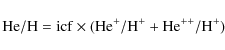
|
(1) |
where icf is a correction factor due to the presence of neutral helium. We assumed
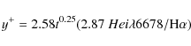
|
(2) |
where t is the electron temperature in units of 104 K (Pagel et al. 1992). As in Sect. 3.3, we assumed
![\begin{figure}
\par\includegraphics[width=8cm,clip]{14154fg13.ps}
\end{figure}](/articles/aa/full_html/2010/09/aa14154-10/img120.png)
|
Figure 13:
|
| Open with DEXTER | |
Figure 14 presents the derived He+ abundances vs. the [O III]![]() 5007/H
5007/H![]() line ratio. With the exception of the data corresponding to the right upper corner of the FLAMES f.o.v., He+/H+ range between 0.075 and 0.090, being higher in the higher excitation zones (i.e. the giant H II region). These values are in agreement with previous measurements of He+/H+ in specific areas (Pagel et al. 1992; Walsh & Roy 1989; Kobulnicky et al. 1997). They are consistent with a scenario without extra N-enrichment and still far, by a factor
line ratio. With the exception of the data corresponding to the right upper corner of the FLAMES f.o.v., He+/H+ range between 0.075 and 0.090, being higher in the higher excitation zones (i.e. the giant H II region). These values are in agreement with previous measurements of He+/H+ in specific areas (Pagel et al. 1992; Walsh & Roy 1989; Kobulnicky et al. 1997). They are consistent with a scenario without extra N-enrichment and still far, by a factor
![]() ,
from the required
,
from the required ![]() 0.12 total helium abundance in the W-R scenario, in particular in the areas enriched with nitrogen.
0.12 total helium abundance in the W-R scenario, in particular in the areas enriched with nitrogen.
![\begin{figure}
\par\includegraphics[width=7.5cm,clip]{14154fg14.ps}
\end{figure}](/articles/aa/full_html/2010/09/aa14154-10/img122.png)
|
Figure 14:
He+ abundance vs. [O III] |
| Open with DEXTER | |
![\begin{figure}
\par\includegraphics[width=7.5cm,clip]{14154fg15.ps}
\end{figure}](/articles/aa/full_html/2010/09/aa14154-10/img123.png)
|
Figure 15:
He++ abundance vs. [O III] |
| Open with DEXTER | |
What about the He++/H+, whose abundance can be determined via the nebular He II![]() 4686 emission line? This line turned out to be rather elusive. Campbell et al. (1986)
mentioned a possible detection in their regions B and C. This
result, however, has not been confirmed afterwards (see López-Sánchez et al. 2007, and references therein). As with the W-R features, we looked for the He II nebular line in each individual spectrum. Those that presented a spatial
continuity were taken to define an area and were co-added before extracting. The selected areas are marked in Fig. 10 with dotted lines. The co-added and extracted spectra of each individual region appear in Fig. 12. In addition to these regions, as mentioned in Sect. 3.5, nebular He II in the W-R 4 and W-R 5 has also been detected.
4686 emission line? This line turned out to be rather elusive. Campbell et al. (1986)
mentioned a possible detection in their regions B and C. This
result, however, has not been confirmed afterwards (see López-Sánchez et al. 2007, and references therein). As with the W-R features, we looked for the He II nebular line in each individual spectrum. Those that presented a spatial
continuity were taken to define an area and were co-added before extracting. The selected areas are marked in Fig. 10 with dotted lines. The co-added and extracted spectra of each individual region appear in Fig. 12. In addition to these regions, as mentioned in Sect. 3.5, nebular He II in the W-R 4 and W-R 5 has also been detected.
These detections are, in general, neither associated with the area of
nitrogen enhancement nor with those presenting W-Rs features. This
lack of coincidence seems difficult to reconcile with a scenario where
this enhancement, and the existence of He++, share a common origin. Moreover, for the purpose of this work, we estimated the
![]() abundances in this areas using:
abundances in this areas using:
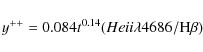
|
(3) |
from Pagel et al. (1992). Derived values for the individual regions are shown Fig. 15 as a function of the [O III]
Since the nebular He II is not associated with the area showing N-enhancement, there is still the open question as to its origin. Garnett et al. (1991) explored the different mechanisms capable of
producing this emission in extragalactic H II regions. The first suggestion is photoionization by fast shocks. However, we have seen in Sect. 3.4,
that shocks do not appear to play a dominant role in the central parts
of NGC 5253. Moreover, the measured ![]() (He II
(He II![]() 4686/H
4686/H![]() )
are
)
are ![]() 3.0 to -2.1, much lower than those predicted by shocks models with
3.0 to -2.1, much lower than those predicted by shocks models with
![]() cm-3 and LMC abundances (
cm-3 and LMC abundances (![]() 1.4 to -0.4, Allen et al. 2008).
1.4 to -0.4, Allen et al. 2008).
Another possibility discussed by Garnett et al. (1991) is hot (
![]() K) stellar ionizing continua. This looks like a plausible explanation for those cases where we had detected nebular He II
K) stellar ionizing continua. This looks like a plausible explanation for those cases where we had detected nebular He II![]() 4686 on top of the blue bump (WR 4 and WR 5).
4686 on top of the blue bump (WR 4 and WR 5).
The last option would be photoionization caused by X-rays. The only point sources detected by Summers et al. (2004)
that fall in our f.o.v. are sources 17-19. This last source
appears to be associated with the Complex #1 and thus, not related
to this discussion (since no nebular He II was detected for this region). Sources 18 and 17 could, however, be associated with He II-1 and
He II-4 detections, respectively. In particular, the latter region coincides with the secondary peak of emission in the H![]() image and is associated with cluster 17 of the sample catalogued by Harris et al. (2004). No satisfactory explanation was found for the cause of the ionization at He II-2 and He II-3.
image and is associated with cluster 17 of the sample catalogued by Harris et al. (2004). No satisfactory explanation was found for the cause of the ionization at He II-2 and He II-3.
3.7 Kinematics of the ionized gas
![\begin{figure}
\par\includegraphics[width=5cm,clip]{14154fg16a.ps}\includegraphi...
...clip]{14154fg16h.ps}\includegraphics[width=5cm,clip]{14154fg16i.ps}
\end{figure}](/articles/aa/full_html/2010/09/aa14154-10/img129.png)
|
Figure 16: Profiles of the main emission lines for representative spectra. The distribution within the FLAMES f.o.v. has been roughly retained. That is: spaxel (1, 1) is located at the upper right corner of the FLAMES IFU and numbering increases towards the left and bottom. The middle row contains the profiles corresponding to the positions of the peaks of continuum emission ( left: Complex #1; centre: Complex #2; right: Complex #3). Spectra in the left column correspond to spaxels associated with the giant H II region ( upper: extension towards the north-west; lower: extension towards the south-east), those in the central column to areas in the centre of the FLAMES f.o.v. and those in the right column to the area associated with Complex #3 ( upper: position towards the north-west; lower: towards the south-east). |
| Open with DEXTER | |
![\begin{figure}
\par\includegraphics[width=5.5cm,clip]{14154fg17a.ps}\includegrap...
...ip]{14154fg17h.ps}\includegraphics[width=5.5cm,clip]{14154fg17i.ps}
\end{figure}](/articles/aa/full_html/2010/09/aa14154-10/img130.png)
|
Figure 17:
Fits in H |
| Open with DEXTER | |
![\begin{figure}
\par\includegraphics[width=17cm,clip]{14154fg18.ps}
\end{figure}](/articles/aa/full_html/2010/09/aa14154-10/img131.png)
|
Figure 18:
Kinematic information derived from the H |
| Open with DEXTER | |
Slit observations in specific regions of this galaxy have demonstrated
that the kinematics of the ionized gas is rather complex, with line
profiles revealing asymmetric wings (e.g. Martin & Kennicutt 1995; López-Sánchez et al. 2007).
These observations usually include the bright core of the galaxy.
However, they might be biased since typically the long slits only
sample specific regions selected by the particular slit placement. The
present data permit a 2D spatially resolved analysis of the
kinematics of the ionized gas in the central area of the galaxy to be
performed, thus overcoming this drawback. We based our analysis on the
strongest emission lines (i.e. mainly H![]() ,
but also H
,
but also H![]() ,
[O III]
,
[O III]![]() 5007, [N II]
5007, [N II]![]() 6584, and [S II]
6584, and [S II]
![]() 6717,6731) where the high S/N permits the line profiles to be fitted with a high degree of accuracy.
6717,6731) where the high S/N permits the line profiles to be fitted with a high degree of accuracy.
In the following, we will present the results derived from H![]() .
Similar results were obtained from the H
.
Similar results were obtained from the H![]() and [O III]
and [O III]![]() 5007 emission lines with differences of
5007 emission lines with differences of
![]()
![]() 2 km s-1 in most cases and always between -5 and 5 km s-1. Results for the only emission lines with remarkable differences in the velocity maps (i.e. [N II]
2 km s-1 in most cases and always between -5 and 5 km s-1. Results for the only emission lines with remarkable differences in the velocity maps (i.e. [N II]![]() 6584 and [S II]
6584 and [S II]
![]() 6717,6731) will be presented, as well.
6717,6731) will be presented, as well.
Typical examples of the different profiles for the main emission lines are shown in Fig. 16.
Lines are ordered by wavelength from bluer (lower) to red (upper)
within each panel. The zero point in the abscissa axis corresponds to
the measured systemic velocity which is
defined as the average of the velocities derived from the main emission
lines for the peak of the continuum emission. We performed an
independent fit for each of the brightest emission lines using
MPFITEXPR (see Sect. 2.3
for details). In general, the line profiles of the individual
spectra cannot be properly reproduced by a single component.
A large percentage of them needed two (and even three)
independent components to reproduce the observed profile reasonably
well. We followed the approach of keeping the analysis as simple as
possible. Thus in those cases where both fits - the one with one
component and the one with several components - reproduced equally
well the line profile, we gave preference to the fit with one
component. Examples of these fits are shown in Fig. 17, which contains the H![]() emission line together with the total fit and the individual components overplot for the spaxels shown in Fig. 16.
Note how the fits for the spaxels in the central area of our f.o.v.
present relatively larger residuals. These can be attributed to a low
surface brightness broad extra component which would be the subject of
a future work. Central wavelengths were translated into heliocentric
velocity taking into account the radial velocity induced by the Earth's
motion at the time of the observation which was evaluated using the
IRAF task rvcorrect. Velocity dispersions were obtained from
the measured FWHM after correcting for the instrumental width and
thermal motions. The width of the thermal profile was derived assuming
emission line together with the total fit and the individual components overplot for the spaxels shown in Fig. 16.
Note how the fits for the spaxels in the central area of our f.o.v.
present relatively larger residuals. These can be attributed to a low
surface brightness broad extra component which would be the subject of
a future work. Central wavelengths were translated into heliocentric
velocity taking into account the radial velocity induced by the Earth's
motion at the time of the observation which was evaluated using the
IRAF task rvcorrect. Velocity dispersions were obtained from
the measured FWHM after correcting for the instrumental width and
thermal motions. The width of the thermal profile was derived assuming ![]() = 11 650 K which translates into a
= 11 650 K which translates into a
![]() of
of ![]() 11 km s-1 for the hydrogen lines. The measured systemic velocity was 392 km s-1. This is slightly lower than the one measured from neutral hydrogen (407 km s-1, Koribalski et al. 2004) according to NED.
11 km s-1 for the hydrogen lines. The measured systemic velocity was 392 km s-1. This is slightly lower than the one measured from neutral hydrogen (407 km s-1, Koribalski et al. 2004) according to NED.
In Fig. 18, we present the velocity fields for the three fitted components derived from the H![]() emission
line. We also included the velocity dispersion map for our broadest
component. Corrected velocity dispersions for the two narrow components
were, in general, subsonic and will not be shown here. The only
exception would be an area at
emission
line. We also included the velocity dispersion map for our broadest
component. Corrected velocity dispersions for the two narrow components
were, in general, subsonic and will not be shown here. The only
exception would be an area at
![]() .
The line profiles in this area show how the narrow component presents a continuity with the two narrow
components at
.
The line profiles in this area show how the narrow component presents a continuity with the two narrow
components at
![]() as
if it were the result of a strong blending of these two components.
However, we were not able to properly deblend these two components by
means of our line fitting technique.
as
if it were the result of a strong blending of these two components.
However, we were not able to properly deblend these two components by
means of our line fitting technique.
From Fig. 18,
it is clear that the movements of the ionized gas are far from simple
rotation. For the discussion we will separate the emitting area into
the zone corresponding to the giant H II region and the rest. The zone of the giant H II region,
occupying roughly the left part of the FLAMES field of view, shows in
the upper part, line profiles that can be explained by two components
while in some spaxels of the lower part a third component was required.
The area of the giant H II region itself, which occupies an area of ![]() 120 pc
120 pc ![]() 60 pc,
requires up to three components to properly reproduce the line
profiles. They were named C1, C2 and C3, according to their
relative fluxes. The first component (i.e. C1) accounts for the
60 pc,
requires up to three components to properly reproduce the line
profiles. They were named C1, C2 and C3, according to their
relative fluxes. The first component (i.e. C1) accounts for the
![]() % of the flux in H
% of the flux in H![]() ,
depending on the considered spaxel. It is relatively narrow and constant, with a
,
depending on the considered spaxel. It is relatively narrow and constant, with a ![]()
![]() 10 km s-1 over a distance of
10 km s-1 over a distance of ![]() 6
6
![]() (
(![]() 110 pc) with slightly bluer velocities in the spaxels associated with the edge of the upper and lower extensions.
110 pc) with slightly bluer velocities in the spaxels associated with the edge of the upper and lower extensions.
The second component (i.e. C2) accounts for the
![]() % of the flux in H
% of the flux in H![]() .
It is symmetric with respect of an axis that goes through the
Complex #1 in the north-south direction. In comparison with
the first component, it presents large velocity variations (i.e.
.
It is symmetric with respect of an axis that goes through the
Complex #1 in the north-south direction. In comparison with
the first component, it presents large velocity variations (i.e.
![]() km s-1 over
km s-1 over
![]() or
or ![]() pc) and is relatively broad (
pc) and is relatively broad (
![]() km s-1). Low surface brightness broad components have been reported in
starburst galaxies using a slit since more than a decade and have been the subject of several theoretical (e.g. Tenorio-Tagle et al. 1997) and observational (e.g. González-Delgado et al. 1994; Castañeda et al. 1990) studies. They usually represent a small fraction (
km s-1). Low surface brightness broad components have been reported in
starburst galaxies using a slit since more than a decade and have been the subject of several theoretical (e.g. Tenorio-Tagle et al. 1997) and observational (e.g. González-Delgado et al. 1994; Castañeda et al. 1990) studies. They usually represent a small fraction (![]() 3-20%) of the total H
3-20%) of the total H![]() flux and have widths of
flux and have widths of ![]()
![]() 700 km s-1. Recently, 2D spectroscopic analysis of very nearby starbursts have shown how locally, the line width is somewhat smaller (
700 km s-1. Recently, 2D spectroscopic analysis of very nearby starbursts have shown how locally, the line width is somewhat smaller (![]()
![]() 50-170 km-1, see Westmoquette et al. 2009, and references therein). This is understood in the context of the so-called Turbulent Mixing Layers (e.g. Slavin et al. 1993).
However, the high surface brightness of C2, together with the
symmetry in the velocity field and its low widths made us to explore an
alternative explanation for it (see Sect. 4.1).
50-170 km-1, see Westmoquette et al. 2009, and references therein). This is understood in the context of the so-called Turbulent Mixing Layers (e.g. Slavin et al. 1993).
However, the high surface brightness of C2, together with the
symmetry in the velocity field and its low widths made us to explore an
alternative explanation for it (see Sect. 4.1).
The third component (i.e. C3) is present in a small area of the field of about 1
![]() 0 diameter (i.e. 18 pc) and centered at about [4
0 diameter (i.e. 18 pc) and centered at about [4
![]() 0, -1
0, -1
![]() 0]. C3 has a width similar to the first
component (C1) but displaced
0]. C3 has a width similar to the first
component (C1) but displaced ![]() 50 km s-1 towards the blue. This third component appears in a location about 1
50 km s-1 towards the blue. This third component appears in a location about 1
![]() 5 south-east to the position of the SSC complexes in the tongue-shaped extension described in Sect. 3.1. This area presents low values of extinction (see Fig. 3) and surface brightness (see Fig. 2). This third component shows indications of more extended weaker emission which was not fitted.
5 south-east to the position of the SSC complexes in the tongue-shaped extension described in Sect. 3.1. This area presents low values of extinction (see Fig. 3) and surface brightness (see Fig. 2). This third component shows indications of more extended weaker emission which was not fitted.
![\begin{figure}
\par\includegraphics[width=5.5cm,clip]{14154fg19a.ps}\includegrap...
...p]{14154fg19b.ps}\includegraphics[width=5.5cm,clip]{14154fg19c.ps}
\end{figure}](/articles/aa/full_html/2010/09/aa14154-10/img144.png)
|
Figure 19:
Difference between the velocity fields derived from the H |
| Open with DEXTER | |
![\begin{figure}
\par\includegraphics[width=5.5cm,clip]{14154fg20a.ps}\includegrap...
...ip]{14154fg20e.ps}\includegraphics[width=5.5cm,clip]{14154fg20f.ps}
\end{figure}](/articles/aa/full_html/2010/09/aa14154-10/img145.png)
|
Figure 20:
Fits in H |
| Open with DEXTER | |
We pointed out before that velocity maps derived from the [N II]![]() 6584 and [S II]
6584 and [S II]
![]() 6717,6731 emission lines showed areas with important differences with respect to the one obtained from H
6717,6731 emission lines showed areas with important differences with respect to the one obtained from H![]() .
This is the case for the giant H II region. Figure 19 contains the measured velocity differences for the
two brighter components (C1 and C2) in the subset of the field corresponding to the giant H II region while Fig. 20 presents examples of the independent fits for H
.
This is the case for the giant H II region. Figure 19 contains the measured velocity differences for the
two brighter components (C1 and C2) in the subset of the field corresponding to the giant H II region while Fig. 20 presents examples of the independent fits for H![]() ,
[N II]
,
[N II]![]() 6584, and [S II]
6584, and [S II]![]() 6717. Differences exist for both, the narrow (i.e. C1) and broad (i.e. C2), components in [N II]
6717. Differences exist for both, the narrow (i.e. C1) and broad (i.e. C2), components in [N II]![]() 6584
and are relatively symmetric with respect to the peak of continuum
emission Complex #1, but with opposite sign and slightly different
directions (PA
6584
and are relatively symmetric with respect to the peak of continuum
emission Complex #1, but with opposite sign and slightly different
directions (PA ![]()
![]() and
and
![]() for C1 and C2 respectively). Also, the range of velocity differences, (
for C1 and C2 respectively). Also, the range of velocity differences, (
![]() )
is larger for C2 than for C1 (
)
is larger for C2 than for C1 (![]() km s-1 and
km s-1 and ![]() km s-1, respectively). As illustrated in the right hand map of Fig. 19, the broad component for the [S II]
km s-1, respectively). As illustrated in the right hand map of Fig. 19, the broad component for the [S II]
![]() 6717,6731 emission lines also shows velocity differences with similar range (
6717,6731 emission lines also shows velocity differences with similar range (
![]()
![]() 60 km s-1), orientation and sign as in the case of the [N II]
60 km s-1), orientation and sign as in the case of the [N II]![]() 6584 emission line.
For the C1 component, no significant differences were found.
Measured differences in C3, with a mean and standard deviation of
-6
6584 emission line.
For the C1 component, no significant differences were found.
Measured differences in C3, with a mean and standard deviation of
-6 ![]() 9 km s-1 and 5
9 km s-1 and 5 ![]() 4 km s-1 for
4 km s-1 for
![]() and
and
![]() respectively, do not appear to be significant. However, since C3 was only detected in seven spaxels (see Fig. 18, bottom left panel) this result has to be treated with caution.
respectively, do not appear to be significant. However, since C3 was only detected in seven spaxels (see Fig. 18, bottom left panel) this result has to be treated with caution.
Similar offsets has been detected in galactic H II regions like Orion (García-Díaz et al. 2008),
but to our knowledge, this is the first time that maps with
such offsets in velocity for different emission
lines in starbursts are presented. This can partially be caused by the
fact that 2D-kinematic analysis of starbursts, from dwarfs (e.g. García-Lorenzo et al. 2008) to more extreme events like LIRGs
(e.g. Alonso-Herrero et al. 2009), are usually based on fitting techniques that impose restrictions between the H![]() and [N II]
and [N II]![]() 6584 central
wavelengths and thus, preventing from detecting such offsets.
An example of work where the main emission lines are fitted
independently is presented by Westmoquette et al. (2007). However,
since they only analyzed the kinematic for H
6584 central
wavelengths and thus, preventing from detecting such offsets.
An example of work where the main emission lines are fitted
independently is presented by Westmoquette et al. (2007). However,
since they only analyzed the kinematic for H![]() ,
it is not possible to assess if they found different kinematics
for the other emission lines. There are however, some works that offer
examples of offsets of this kind using a slit. In particular López-Sánchez et al. (2007) report also an offset between the [N II]
,
it is not possible to assess if they found different kinematics
for the other emission lines. There are however, some works that offer
examples of offsets of this kind using a slit. In particular López-Sánchez et al. (2007) report also an offset between the [N II]![]() 6584 and the H
6584 and the H![]() emission line of
emission line of ![]() 10 km s-1, similar to what we have measured for C1 in the upper part of our f.o.v.
10 km s-1, similar to what we have measured for C1 in the upper part of our f.o.v.
The second region of interest is located in the right (south-west) part
of the FLAMES field of view. Emission there shows narrow lines
with velocity dispersion dominated by the thermal width. In some
areas (the north-east corner in Fig. 18),
two narrow lines were needed to better reproduce the line profile.
The primary component (i.e. C1) shows a symmetric velocity pattern
with respect to the twin clusters associated with the peak of
emission #3. A velocity gradient in the north-west to
south-east direction is clear with a
![]() km-1 over about 4
km-1 over about 4
![]() 0 (linear scale of
0 (linear scale of ![]() 75 pc). The secondary component traces a shell blue-shifted
75 pc). The secondary component traces a shell blue-shifted ![]() 40 km s-1 in the western corner (see Fig. 18, upper right panel). Note that C2, although relatively narrow, is a bit broader than the thermal width (Fig. 18, bottom right panel). This component accounts for
40 km s-1 in the western corner (see Fig. 18, upper right panel). Note that C2, although relatively narrow, is a bit broader than the thermal width (Fig. 18, bottom right panel). This component accounts for
![]() % of the H
% of the H![]() flux
in this area. No significant differences in the velocity fields
and the velocity dispersion maps for the main emission lines have been
found in this area.
flux
in this area. No significant differences in the velocity fields
and the velocity dispersion maps for the main emission lines have been
found in this area.
4 Discussion
4.1 The giant H II region
The most interesting area of NGC 5253 in the present data
covers the left (north-east) part of the FLAMES field of view.
In previous sections we have seen that this area is occupied by a
giant
H II region which: i) harbors two very
massive and young SSCs at its centre (i.e. Complex #1);
ii) presents high levels of extinction, being larger in the upper
part of the f.o.v.; iii) has high electron densities as traced by
both the sulphur and the argon line ratios, and again are also larger
in the upper part of the f.o.v.; iv) presents an excess in the
[N II]![]() 6584/H
6584/H![]() line ratio with respect to [S II]
line ratio with respect to [S II]
![]() 6717,6731/H
6717,6731/H![]() which, if interpreted as N-enrichment, indicates an outward gradient of extra nitrogen from a point at
which, if interpreted as N-enrichment, indicates an outward gradient of extra nitrogen from a point at
![]() towards the north-west of the peak of continuum emission at
Complex #1; v) presents W-R features, implying a young
age for the harboured stellar population; vi) displays complex
kinematics, not coincident in all the emission lines, that require a
minimum of three components to reproduce the line profiles. How does
all this evidence fit together into a coherent picture?
towards the north-west of the peak of continuum emission at
Complex #1; v) presents W-R features, implying a young
age for the harboured stellar population; vi) displays complex
kinematics, not coincident in all the emission lines, that require a
minimum of three components to reproduce the line profiles. How does
all this evidence fit together into a coherent picture?
![\begin{figure}
\par\includegraphics[width=7.5cm,clip]{14154fg21.eps}
\end{figure}](/articles/aa/full_html/2010/09/aa14154-10/img155.png)
|
Figure 21: Sketch showing the different elements associated with the area of the giant H II region. The two massive SSCs (stars in the circles) expel material (red and blue half moons) which encounter quiescent gas (grey shell). Regions of dust extinction are represented by the two wavy sheets. |
| Open with DEXTER | |
In Fig. 21, we sketch a plausible scenario compatible with all these results. Here, the broad component (C2) would trace an outflow created by the two SSCs at Complex #1 while the two narrow components (C1 and C3) would be caused by a shell of previously existing quiescent gas that has been reached by the ionization front. Different grades of grey in Fig. 21 in the shell represent the different densities observed in the upper and lower part of the FLAMES f.o.v., while two wavy sheets in two grades of grey have been used to represent the differences in extinction between these two halves. Due to this extinction distribution, in the upper (i.e. north-western) half of the H II region, the observer cannot see the further part of the shell, while in the lower (i.e. south-eastern) half both parts are visible and are detected as a single broader component when approaching the vertex of the oval.
As in Sect. 3.3, we formed [S II]![]() 6717/[S II]
6717/[S II]![]() 6731
maps for the individual kinematic components and measured the mean and
standard deviation for the sulphur line ratio in two 4
6731
maps for the individual kinematic components and measured the mean and
standard deviation for the sulphur line ratio in two 4 ![]() 4 spaxel squares sampling the upper and lower part of the giant H II region. Although the standard deviations are large (
4 spaxel squares sampling the upper and lower part of the giant H II region. Although the standard deviations are large (
![]() ), results support this sketch. While the broad component presented similar line ratios in both areas (
), results support this sketch. While the broad component presented similar line ratios in both areas (
![]() implying
densities of
implying
densities of ![]() 470 cm-3), the narrow component presented somewhat lower line ratios in the upper part than in the lower one (
470 cm-3), the narrow component presented somewhat lower line ratios in the upper part than in the lower one (![]() 1.11 vs.
1.11 vs. ![]() 1.25) implying densities for the shell of
1.25) implying densities for the shell of ![]() 390 cm-3 and
390 cm-3 and ![]() 180 cm-3, respectively. Also, we created (noisier) [N II]
180 cm-3, respectively. Also, we created (noisier) [N II]![]() 6584/H
6584/H![]() ,
[S II]
,
[S II]
![]() 6717,6731/H
6717,6731/H![]() ,
and [O III]
,
and [O III]![]() 5007/H
5007/H![]() line maps and compared the relation between [S II]
line maps and compared the relation between [S II]
![]() 6717,6731/H
6717,6731/H![]() and [N II]
and [N II]![]() 6584/H
6584/H![]() for the individual components. The three fitted components present
extra nitrogen in an area coinciding with the one derived
from one-gaussian fitting. This differs from the findings
for Mrk 996, a galaxy with several kinematically
distinct components where only the broad one presented N-enrichment,
with an abundance
for the individual components. The three fitted components present
extra nitrogen in an area coinciding with the one derived
from one-gaussian fitting. This differs from the findings
for Mrk 996, a galaxy with several kinematically
distinct components where only the broad one presented N-enrichment,
with an abundance
![]() 20 times larger than the one for the narrow component (see James et al. 2009).
Still, in NGC 5253, the N-enrichment in the
broad component is larger than in the narrow one by a factor of
20 times larger than the one for the narrow component (see James et al. 2009).
Still, in NGC 5253, the N-enrichment in the
broad component is larger than in the narrow one by a factor of ![]() 1.7 which is consistent with the scenario sketched above. Moreover, while the [O III]
1.7 which is consistent with the scenario sketched above. Moreover, while the [O III]![]() 5007/H
5007/H![]() maps are relatively similar for both components
maps are relatively similar for both components![]() (not shown), those associated to [N II]
(not shown), those associated to [N II]![]() 6584/H
6584/H![]() and specially to (the more shock sensitive) [S II]
and specially to (the more shock sensitive) [S II]
![]() 6717,6731/H
6717,6731/H![]() line
ratio display a relatively different ionization degree with larger
values for C1 than for C2. This is also
consistent with the presented scenario since a larger contribution due
to shocks is expected in the area where the outflowing material
encounters the pre-existent gas.
line
ratio display a relatively different ionization degree with larger
values for C1 than for C2. This is also
consistent with the presented scenario since a larger contribution due
to shocks is expected in the area where the outflowing material
encounters the pre-existent gas.
An interesting result of the previous section was the offsets derived
for the velocities of the different species, in particular
nitrogen and sulphur. To our knowledge, this is the first time
that maps showing this kind of offsets are reported in an starburst
galaxy. Similar phenomena have already been reported in much closer
regions of star formation. For example, observations in the Galactic
Orion Nebula, a much less extreme event in terms of star formation,
show how H![]() and [O III]
and [O III]![]() 5007 display similar velocities while [N II]
5007 display similar velocities while [N II]![]() 6584 and [S II]
6584 and [S II]
![]() 6717,6731 are shifted by
6717,6731 are shifted by ![]() 4-5 km s-1 (García-Díaz et al. 2008),
an order of magnitude smaller than the shifts found for NGC 5253.
Also, self-consistent dynamic models of steady ionization fronts point
towards the detection of such
differences (Henney et al. 2005). In the context of the scenario sketched in Fig. 21, the offsets in C2 would fit if [N II]
4-5 km s-1 (García-Díaz et al. 2008),
an order of magnitude smaller than the shifts found for NGC 5253.
Also, self-consistent dynamic models of steady ionization fronts point
towards the detection of such
differences (Henney et al. 2005). In the context of the scenario sketched in Fig. 21, the offsets in C2 would fit if [N II]![]() 6584 (and [S II]
6584 (and [S II]
![]() 6717,6731) traced the outer parts in an outflow which has a Hubble flow (i.e. velocity proportional to radius).
6717,6731) traced the outer parts in an outflow which has a Hubble flow (i.e. velocity proportional to radius).
Finally, an estimate of the time scales associated with the pollution
process can be determined by using the velocity for the outflow derived
in Sect. 3.7.
Assuming that this traces the velocity of nitrogen contamination of the
ISM, the detected pollution extending up to distances of ![]() 60 pc took place over only
60 pc took place over only ![]() 1.3-1.7 Myr.
This supports the idea that the nitrogen dilution is a relatively fast
process and is consistent with the shortage of observed systems
presenting this kind of chemical inhomogeneity.
1.3-1.7 Myr.
This supports the idea that the nitrogen dilution is a relatively fast
process and is consistent with the shortage of observed systems
presenting this kind of chemical inhomogeneity.
4.2 The area associated with the older stellar clusters
The rightmost (south-west) part of the FLAMES f.o.v. presents a
different picture. We have seen that this region: i) is associated
with two relatively old (![]() 70 and
70 and ![]() 110 Myr) and massive (3 and 7
110 Myr) and massive (3 and 7 ![]() 10
10
![]() )
clusters (Harris et al. 2004);
ii) presents moderate levels of extinction, being higher in the
lower part of the FLAMES field of view; iii) has very
low
)
clusters (Harris et al. 2004);
ii) presents moderate levels of extinction, being higher in the
lower part of the FLAMES field of view; iii) has very
low ![]() and lower than 100 cm-3 in the upper corner; iv) the H
and lower than 100 cm-3 in the upper corner; iv) the H![]() surface brightness is very low (i.e. one and two orders of magnitude smaller than in the giant H II region
for the upper and lower portions respectively); v) displays two
distinct kinematic components in the upper part of the f.o.v..
Noteworthy is that two supernova remnant candidates have been detected
in the area (Labrie & Pritchet 2006). One of them (S001) appears very close in projection to the massive clusters at
surface brightness is very low (i.e. one and two orders of magnitude smaller than in the giant H II region
for the upper and lower portions respectively); v) displays two
distinct kinematic components in the upper part of the f.o.v..
Noteworthy is that two supernova remnant candidates have been detected
in the area (Labrie & Pritchet 2006). One of them (S001) appears very close in projection to the massive clusters at ![]() [-5
[-5
![]() 0, 1
0, 1
![]() 0]. The second one (S002) is located, just outside of the FLAMES f.o.v., at the right upper corner.
0]. The second one (S002) is located, just outside of the FLAMES f.o.v., at the right upper corner.
Table 5: Integrated line ratios for the rightmost (south-west) part of the FLAMES f.o.v.
The first question to consider is if any of the kinematic components is
related to the supernova remnant candidates. However, our measured
velocity dispersions are much more lower than expansion velocities of
typical supernova remnants (i.e. NGC 1952, 1450 km s-1 Osterbrock & Ferland 2006).
Moreover, we created two integrated spectra for the upper and the lower
part of the area. Line ratio for both components of the upper part and
for the lower part were relatively similar (i.e. within ![]() 0.1 dex, see Table 5) and much lower than those expected for a supernova remnant (e.g. NGC 1952, Osterbrock & Ferland 2006).
Thus, supernova remnants are not obviously the cause of the observed
kinematics and physical properties of the ionized gas in this region.
0.1 dex, see Table 5) and much lower than those expected for a supernova remnant (e.g. NGC 1952, Osterbrock & Ferland 2006).
Thus, supernova remnants are not obviously the cause of the observed
kinematics and physical properties of the ionized gas in this region.
Instead, given that all the three components present similar line ratios - consistent with ionization caused by stars - and similar line widths, a more plausible scenario would be that where all the components are part of a common picture. Given the age of the clusters, and the velocity differences between the three components, this area can be viewed as a snapshot of a more evolved version of what is happening in the left part of the FLAMES f.o.v. The clusters have managed to clear out their environment. Only a broken shell made out of previously quiescent gas remains ionized by the remaining hot stars and moving away from the clusters with little evidence for high velocity outflow. Figure 22 presents a sketch of the different elements associated with this area.
5 Summary
We present a thorough study of the ionized gas and its relation with
the stellar population of NGC 5253 by mapping the central
212 pc ![]() 134 pc in a continuous and
unbiased manner using the ARGUS IFU unit of FLAMES. The analysis of the data have yield the following results.
134 pc in a continuous and
unbiased manner using the ARGUS IFU unit of FLAMES. The analysis of the data have yield the following results.
- 1.
- We obtained a 2D detailed map for the extinction suffered by the ionized gas, finding an offset of
 between the peak of the optical continuum and the extinction peak, in agreement with findings in the infrared.
- 2.
- We compared the extinction suffered by gas and stars by
defining ad hoc broad-band colours. We have shown the importance
of using line-free filters when performing this comparison and found
that
stars suffer less extinction than the ionized gas by a factor
 ,
similar to the findings in other starburst galaxies.
,
similar to the findings in other starburst galaxies.
- 3.
- We derived
 sensitive line ratio maps. The one involving the sulphur lines shows a gradient from 790 cm-3 at the peak of emission in the giant H II region described by Calzetti et al. (1997) outwards. The argon line ratio is only detected in the area associated with the giant H II region and traces the highest density (
 cm-3) regions.
- 4.
- We studied the ionization structure by means of the maps of
line ratios involved in the BPT diagrams. The spatial distribution
of the [S II]
 6717,6731/H
 and [O III]
 5007/H
 line ratios follows that for the flux distribution of the ionized gas. On the contrary, the [N II]6584/H map shows a completely different structure.
![\begin{figure}
\par\includegraphics[width=7.5cm,clip]{14154fg22.eps}
\end{figure}](/articles/aa/full_html/2010/09/aa14154-10/Timg162.png)
Figure 22: Sketch showing the different elements associated with the right part of the FLAMES field of view. The two massive SSCs (stars in the circles) have already expelled their material and are seen as relatively quiescent ionized shells (shown in grey). Differences in extinction are represented by two wavy sheets.
Open with DEXTER - 5.
- We evaluated the possible ionization mechanisms through the
position of these line ratios in the diagnostic diagrams and comparing
with the predictions of models. All our line ratios are compatible with
photoionization caused by stars. The [S II]
6717,6731/H
indicated a somewhat higher ionization degree that might be evidence of
some contribution of shocks to the measured line ratios. Part of the
data in the diagram involving the [N II]6584/H line
ratio are distributed in a distinct cloud. This can be explained within
the local N-enrichment scenario proposed for this galaxy.
- 6.
- We delimited very precisely the area presenting local N-enrichment. It occupies the whole giant H II region, including the two extensions towards the upper and lower part of the FLAMES field of view, peaking at
 1
1
 5 from the peak of emission in the continuum and almost coincident (i.e. at
  pc) with the peak of extinction.
- 7.
- We located the areas that could contain Wolf-Rayet stars by looking for the blue bump. We confirmed the existence of W-R stars associated with the nucleus and the brightest cluster in the ultraviolet. W-R stars are distributed in a wider area than the one presenting N-enrichment and in a more irregular manner. We were able to identified one (or more) clusters with ages compatible with the existence of W-R stars in all but one (i.e. W-R 5) of our delineated regions with a W-R signature.
- 8.
- If the scenario of N-enrichment caused by W-R stars turns out to be applicable, only the W-R detected at the core (Complex #1), and perhaps in the two extensions of the Giant H II region, can be considered the cause of the local N-enrichment, according to the correlation of the spatial distribution of W-R features and N-enrichment.
- 9.
- We measured the He+ and He++ abundances. He+/H+ is 0.08-0.09 in most of our field of view except for an area of 2


 in the upper right corner, far away from the main ionization source. We detected the nebular He II4686 emission
line in areas not coincident, in general, with those presenting
W-R features, nor with the one presenting N-enrichment.
Abundances in He II were always
in the upper right corner, far away from the main ionization source. We detected the nebular He II4686 emission
line in areas not coincident, in general, with those presenting
W-R features, nor with the one presenting N-enrichment.
Abundances in He II were always  0.0005.
Given the depth and unbiased mapping of the present data, we can
exclude the possibility of further detections of larger quantities
of He++ based on optical observations in the nuclear
region of NGC 5253. This result is difficult to reconcile with the
scenario of N-enrichment caused by W-R stars and favours a suggestion where the N-enrichment arises during the late O-star wind phase.
0.0005.
Given the depth and unbiased mapping of the present data, we can
exclude the possibility of further detections of larger quantities
of He++ based on optical observations in the nuclear
region of NGC 5253. This result is difficult to reconcile with the
scenario of N-enrichment caused by W-R stars and favours a suggestion where the N-enrichment arises during the late O-star wind phase.
- 10.
- We studied the kinematics of the ionized gas by using velocity
fields and velocity dispersion maps for the main emission lines. We
needed up to three components to properly reproduce the line
profiles. In particular, one of the components associated with the
Giant H II region presents supersonic widths and [N II]6584 and [S II]
6717,6731 emission lines shifted up to 40 km s-1 with respect to H.
Also, one of the narrow components shows velocity offsets in the [N II]6584 line of up to 20 km s-1. This is the first time that maps providing such offsets for a starburst galaxy have been presented.
- 11.
- We provide a scenario for the event occurring at the Giant H II region. The two SSCs are producing an outflow that encounters previously existing quiescent gas. The scenario is consistent with the measured extinction structure, electron densities and kinematics.
- 12.
- We explain the different elements in the right (south-west)
part of the FLAMES field of view as a more evolved stage of a
similar scenario where the clusters have now cleared their local
environment. This is supported by the low electron densities and H surface brightness as well as the kinematics in this area.
We thank Peter Weilbacher for his help in the initial stages of this project as well as Christer Sandin for useful discussions about differential atmospherical refraction correction. We also thank the anonymous referee for his/her careful and detailed review of the manuscript. Based on observations carried out at the European Southern Observatory, Paranal (Chile), programme 078.B-0043(A). This paper uses the plotting package jmaplot, developed by Jesús Maíz-Apellániz, http://dae45.iaa.csic.es:8080/ jmaiz/software. This research made use of the NASA/IPAC Extragalactic Database (NED), which is operated by the Jet Propulsion Laboratory, California Institute of Technology, under contract with the National Aeronautics and Space Administration. A.M.I. is supported by the Spanish Ministry of Science and Innovation (MICINN) under the program ``Specialization in International Organisations'', Ref. ES2006-0003. This work has been partially funded by the Spanish PNAYA, projects ESTALLIDOS (grants AYA2007-7765-C01 and C02) and CSD2006 - 00070 ''1st Science with GTC'' from the CONSOLIDER 2010 programme of the Spanish MICINN.
References
- Allen, M. G., Groves, B. A., Dopita, M. A., Sutherland, R. S., & Kewley, L. J. 2008, ApJS, 178, 20 [Google Scholar]
- Alonso-Herrero, A., Rieke, G. H., Rieke, M. J., & Scoville, N. Z. 2002, AJ, 124, 166 [NASA ADS] [CrossRef] [Google Scholar]
- Alonso-Herrero, A., Takagi, T., Baker, A. J., et al. 2004, ApJ, 612, 222 [NASA ADS] [CrossRef] [Google Scholar]
- Alonso-Herrero, A., García-Marín, M., Monreal-Ibero, A., et al. 2009, A&A, 506, 1541 [NASA ADS] [CrossRef] [EDP Sciences] [Google Scholar]
- Asplund, M., Grevesse, N., Sauval, A. J., Allende Prieto, C., & Kiselman, D. 2004, A&A, 417, 751 [NASA ADS] [CrossRef] [EDP Sciences] [Google Scholar]
- Baldwin, J. A., Phillips, M. M., & Terlevich, R. 1981, PASP, 93, 5 [NASA ADS] [CrossRef] [EDP Sciences] [Google Scholar]
- Bordalo, V., Plana, H., & Telles, E. 2009, ApJ, 696, 1668 [NASA ADS] [CrossRef] [Google Scholar]
- Brinchmann, J., Kunth, D., & Durret, F. 2008, A&A, 485, 657 [NASA ADS] [CrossRef] [EDP Sciences] [Google Scholar]
- Calzetti, D., Kinney, A. L., & Storchi-Bergmann, T. 1994, ApJ, 429, 582 [NASA ADS] [CrossRef] [Google Scholar]
- Calzetti, D., Meurer, G. R., Bohlin, R. C., et al. 1997, AJ, 114, 1834 [NASA ADS] [CrossRef] [Google Scholar]
- Calzetti, D., Harris, J., Gallagher, III, J. S., et al. 2004, AJ, 127, 1405 [NASA ADS] [CrossRef] [Google Scholar]
- Campbell, A., Terlevich, R., & Melnick, J. 1986, MNRAS, 223, 811 [NASA ADS] [CrossRef] [Google Scholar]
- Cardelli, J. A., Clayton, G. C., & Mathis, J. S. 1989, ApJ, 345, 245 [NASA ADS] [CrossRef] [Google Scholar]
- Castañeda, H. O., Vílchez, J. M., & Copetti, M. V. F. 1990, ApJ, 365, 164 [NASA ADS] [CrossRef] [Google Scholar]
- Conti, P. S. 1976, Memoires of the Société Royale des Sciences de Liège, 9, 193 [Google Scholar]
- Conti, P. S., Crowther, P. A., & Leitherer, C. 2008, From Luminous Hot Stars to Starburst Galaxies, ed. P. S. Conti, P. A. Crowther, & C. Leitherer (Cambridge University Press) [Google Scholar]
- Cresci, G., Vanzi, L., & Sauvage, M. 2005, A&A, 433, 447 [NASA ADS] [CrossRef] [EDP Sciences] [Google Scholar]
- Dopita, M. A., Fischera, J., Sutherland, R. S., et al. 2006, ApJS, 167, 177 [NASA ADS] [CrossRef] [Google Scholar]
- Esteban, C., Peimbert, M., Torres-Peimbert, S., & Rodríguez, M. 2002, ApJ, 581, 241 [NASA ADS] [CrossRef] [Google Scholar]
- Fluks, M. A., Plez, B., The, P. S., et al. 1994, A&AS, 105, 311 [NASA ADS] [Google Scholar]
- García-Díaz, M. T., Henney, W. J., López, J. A., & Doi, T. 2008, Rev. Mex. Astron. Astrofís., 44, 181 [Google Scholar]
- García-Lorenzo, B., Cairós, L. M., Caon, N., Monreal-Ibero, A., & Kehrig, C. 2008, ApJ, 677, 201 [NASA ADS] [CrossRef] [Google Scholar]
- Garnett, D. R., Kennicutt, Jr., R. C., Chu, Y., & Skillman, E. D. 1991, ApJ, 373, 458 [NASA ADS] [CrossRef] [Google Scholar]
- González-Delgado, R. M., Pérez, E., Tenorio-Tagle, G., et al. 1994, ApJ, 437, 239 [NASA ADS] [CrossRef] [Google Scholar]
- González-Riestra, R., Rego, M., & Zamorano, J. 1987, A&A, 186, 64 [NASA ADS] [Google Scholar]
- Haro, G. 1956, AJ, 61, 178 [NASA ADS] [CrossRef] [Google Scholar]
- Harris, J., Calzetti, D., Gallagher, III, J. S., Smith, D. A., & Conselice, C. J. 2004, ApJ, 603, 503 [NASA ADS] [CrossRef] [Google Scholar]
- Henney, W. J., Arthur, S. J., Williams, R. J. R., & Ferland, G. J. 2005, ApJ, 621, 328 [NASA ADS] [CrossRef] [Google Scholar]
- Holovatyy, V. V., & Melekh, B. Y. 2002, Astron. Rep., 46, 779 [NASA ADS] [CrossRef] [Google Scholar]
- Hora, J. L., Latter, W. B., & Deutsch, L. K. 1999, ApJS, 124, 195 [NASA ADS] [CrossRef] [Google Scholar]
- Izotov, Y. I., Schaerer, D., Blecha, A., et al. 2006, A&A, 459, 71 [NASA ADS] [CrossRef] [EDP Sciences] [Google Scholar]
- James, B. L., Tsamis, Y. G., Barlow, M. J., et al. 2009, MNRAS, 398, 2 [NASA ADS] [CrossRef] [Google Scholar]
- Karachentsev, I. D., Tully, R. B., Dolphin, A., et al. 2007, AJ, 133, 504 [NASA ADS] [CrossRef] [Google Scholar]
- Kauffmann, G., Heckman, T. M., Tremonti, C., et al. 2003, MNRAS, 346, 1055 [Google Scholar]
- Kehrig, C., Vílchez, J. M., Sánchez, S. F., et al. 2008, A&A, 477, 813 [NASA ADS] [CrossRef] [EDP Sciences] [Google Scholar]
- Kennicutt, Jr., R. C. 1992, ApJS, 79, 255 [NASA ADS] [CrossRef] [Google Scholar]
- Kewley, L. J., & Dopita, M. A. 2002, ApJS, 142, 35 [NASA ADS] [CrossRef] [Google Scholar]
- Kewley, L. J., Dopita, M. A., Sutherland, R. S., Heisler, C. A., & Trevena, J. 2001, ApJ, 556, 121 [Google Scholar]
- Kobulnicky, H. A., & Skillman, E. D. 2008, AJ, 135, 527 [NASA ADS] [CrossRef] [Google Scholar]
- Kobulnicky, H. A., Skillman, E. D., Roy, J.-R., Walsh, J. R., & Rosa, M. R. 1997, ApJ, 477, 679 [NASA ADS] [CrossRef] [Google Scholar]
- Kobulnicky, H. A., Kennicutt, Jr., R. C., & Pizagno, J. L. 1999, ApJ, 514, 544 [NASA ADS] [CrossRef] [Google Scholar]
- Koribalski, B. S., Staveley-Smith, L., Kilborn, V. A., et al. 2004, AJ, 128, 16 [NASA ADS] [CrossRef] [Google Scholar]
- Kunth, D., & Östlin, G. 2000, A&A Rev., 10, 1 [NASA ADS] [CrossRef] [Google Scholar]
- Labrie, K., & Pritchet, C. J. 2006, ApJS, 166, 188 [NASA ADS] [CrossRef] [Google Scholar]
- Lagos, P., Telles, E., Muñoz-Tuñón, C., et al. 2009, AJ, 137, 5068 [NASA ADS] [CrossRef] [Google Scholar]
- Leitherer, C., Schaerer, D., Goldader, J. D., et al. 1999, ApJS, 123, 3 [NASA ADS] [CrossRef] [Google Scholar]
- López-Sánchez, Á. R., Esteban, C., García-Rojas, J., Peimbert, M., & Rodríguez, M. 2007, ApJ, 656, 168 [NASA ADS] [CrossRef] [Google Scholar]
- Markwardt, C. B. 2009, in ASP Conf. Ser., ed. D. A. Bohlender, D. Durand, & P. Dowler, 411, 251 [Google Scholar]
- Martin, C. L. 1998, ApJ, 506, 222 [NASA ADS] [CrossRef] [Google Scholar]
- Martin, C. L., & Kennicutt, Jr., R. C. 1995, ApJ, 447, 171 [NASA ADS] [CrossRef] [Google Scholar]
- Martín-Hernández, N. L., Schaerer, D., & Sauvage, M. 2005, A&A, 429, 449 [NASA ADS] [CrossRef] [EDP Sciences] [Google Scholar]
- Osterbrock, D. E., & Ferland, G. J. 2006, Astrophysics of gaseous nebulae and active galactic nuclei, ed. D. E. Osterbrock, & G. J. Ferland [Google Scholar]
- Pagel, B. E. J., Simonson, E. A., Terlevich, R. J., & Edmunds, M. G. 1992, MNRAS, 255, 325 [NASA ADS] [CrossRef] [Google Scholar]
- Pasquini, L., Ávila, G., Blecha, A., et al. 2002, The Messenger, 110, 1 [NASA ADS] [Google Scholar]
- Pérez-Montero, E., & Contini, T. 2009, MNRAS, 398, 949 [NASA ADS] [CrossRef] [Google Scholar]
- Rieke, G. H., & Lebofsky, M. J. 1985, ApJ, 288, 618 [NASA ADS] [CrossRef] [Google Scholar]
- Sakai, S., Ferrarese, L., Kennicutt, Jr., R. C., & Saha, A. 2004, ApJ, 608, 42 [NASA ADS] [CrossRef] [Google Scholar]
- Sanders, D. B., Mazzarella, J. M., Kim, D.-C., Surace, J. A., & Soifer, B. T. 2003, AJ, 126, 1607 [Google Scholar]
- Schaerer, D. 1996, ApJ, 467, L17 [NASA ADS] [CrossRef] [Google Scholar]
- Schaerer, D., Contini, T., Kunth, D., & Meynet, G. 1997, ApJ, 481, L75 [NASA ADS] [CrossRef] [Google Scholar]
- Schaerer, D., Contini, T., & Pindao, M. 1999, A&AS, 136, 35 [NASA ADS] [CrossRef] [EDP Sciences] [Google Scholar]
- Schlegel, D. J., Finkbeiner, D. P., & Davis, M. 1998, ApJ, 500, 525 [NASA ADS] [CrossRef] [Google Scholar]
- Shaw, R. A., & Dufour, R. J. 1995, PASP, 107, 896 [NASA ADS] [CrossRef] [Google Scholar]
- Slavin, J. D., Shull, J. M., & Begelman, M. C. 1993, ApJ, 407, 83 [NASA ADS] [CrossRef] [Google Scholar]
- Stasinska, G., Cid Fernandes, R., Mateus, A., Sodré, L., & Asari, N. V. 2006, MNRAS, 371, 972 [NASA ADS] [CrossRef] [Google Scholar]
- Strickland, D. K., & Stevens, I. R. 1999, MNRAS, 306, 43 [NASA ADS] [CrossRef] [Google Scholar]
- Summers, L. K., Stevens, I. R., Strickland, D. K., & Heckman, T. M. 2004, MNRAS, 351, 1 [NASA ADS] [CrossRef] [Google Scholar]
- Taylor, V. A., Jansen, R. A., Windhorst, R. A., Odewahn, S. C., & Hibbard, J. E. 2005, ApJ, 630, 784 [NASA ADS] [CrossRef] [Google Scholar]
- Tenorio-Tagle, G., Munoz-Tunon, C., Perez, E., & Melnick, J. 1997, ApJ, 490, L179 [NASA ADS] [CrossRef] [Google Scholar]
- Tsamis, Y. G., Barlow, M. J., Liu, X., Danziger, I. J., & Storey, P. J. 2003, MNRAS, 345, 186 [NASA ADS] [CrossRef] [Google Scholar]
- Turner, J. L., Beck, S. C., & Ho, P. T. P. 2000, ApJ, 532, L109 [NASA ADS] [CrossRef] [PubMed] [Google Scholar]
- Turner, J. L., Beck, S. C., Crosthwaite, L. P., et al. 2003, Nature, 423, 621 [NASA ADS] [CrossRef] [PubMed] [Google Scholar]
- van den Bergh, S. 1980, PASP, 92, 122 [NASA ADS] [CrossRef] [Google Scholar]
- Veilleux, S., & Osterbrock, D. E. 1987, ApJS, 63, 295 [NASA ADS] [CrossRef] [Google Scholar]
- Vílchez, J. M., & Iglesias-Páramo, J. 1998, ApJ, 508, 248 [NASA ADS] [CrossRef] [Google Scholar]
- Walsh, J. R., & Roy, J.-R. 1989, MNRAS, 239, 297 [NASA ADS] [CrossRef] [Google Scholar]
- Wang, W., Liu, X., Zhang, Y., & Barlow, M. J. 2004, A&A, 427, 873 [NASA ADS] [CrossRef] [EDP Sciences] [Google Scholar]
- Westmoquette, M. S., Smith, L. J., Gallagher, J. S., & Exter, K. M. 2007, MNRAS, 381, 913 [NASA ADS] [CrossRef] [Google Scholar]
- Westmoquette, M. S., Gallagher, J. S., Smith, L. J., et al. 2009, ApJ, 706, 1571 [NASA ADS] [CrossRef] [Google Scholar]
Footnotes
- ... spectroscopy
- Based on observations collected at the European Organisation for Astronomical Research in the Southern Hemisphere, Chile (ESO Programme 078.B-0043).
- ... (version 1.0)
- http://www.eso.org/projects/dfs/dfs-shared/web/vlt/vlt-instrument-pipelines.html
- ... IRAF
- The Image Reduction and Analysis Facility IRAF is distributed by the National Optical Astronomy Observatories which is operated by the association of Universities for Research in Astronomy, Inc. under cooperative agreement with the National Science Foundation.
- ... MPFITEXPR
- See http://purl.com/net/mpfit
- ... NED
- See http://nedwww.ipac.caltech.edu/
- ...
0]
- Hereafter, the different quoted positions will be refereed as [
,
]
and using the FLAMES f.o.v. as reference.
- ... components
- C3 is not considered here, since the so-called map would be associated to
 spaxels, depending on the line ratio.
All Tables
Table 1: Basic data for NGC 5253.
Table 2: Observation log.
Table 3: Main reference clusters.
Table 4: Ages of the clusters associated with the W-R regions according to different indicators.
Table 5: Integrated line ratios for the rightmost (south-west) part of the FLAMES f.o.v.
All Figures
|
|
Figure 1:
False colour image in filters F435W (B, blue), F658N (
|
| Open with DEXTER | |
| In the text | |
|
|
Figure 2:
Top: stellar component distribution as traced by a continuum map made from the average flux in the spectral range
6525-6545 Å and
6600-6620 Å. Bottom: ionized gas distribution as traced by the H |
| Open with DEXTER | |
| In the text | |
|
|
Figure 3:
Reddening map obtained from the hydrogen recombination lines assuming H |
| Open with DEXTER | |
| In the text | |
|
|
Figure 4:
Relation between the derived reddening and a colour similar to
|
| Open with DEXTER | |
| In the text | |
|
|
Figure 5: Line free colour map. The simulated filters have been defined as explained in Fig. 4. The position of the three main peaks of continuum emission are shown for reference. |
| Open with DEXTER | |
| In the text | |
|
|
Figure 6: Maps for the line ratios sensitive to the electron density. The position of the three main peaks of continuum emission are shown as crosses for reference. The displayed ranges in the line ratios imply electron densities of <10-790 cm-3 and 190-8750 cm-3 for the sulphur and argon line ratio, respectively. |
| Open with DEXTER | |
| In the text | |
|
|
Figure 7:
Emission line ratio maps. Up: |
| Open with DEXTER | |
| In the text | |
|
|
Figure 8:
Position of the individual spaxels in NGC 5253 in the diagnostic diagrams
proposed by Veilleux & Osterbrock (1987). Data points above and below the 3- |
| Open with DEXTER | |
| In the text | |
|
|
Figure 9:
[S II]
|
| Open with DEXTER | |
| In the text | |
|
|
Figure 10:
Spaxels with [N II] |
| Open with DEXTER | |
| In the text | |
|
|
Figure 11: Spectra showing Wolf-Rayet features. The first spectrum has been extracted from a low surface brightness area in the upper right corner of the FLAMES field of view and is presented here as reference. The positions of the nebular emission lines have been indicated with blue ticks and labels, while those corresponding to Wolf-Rayet features appear in red. The position and extent of the regions are indicated in Fig. 10. |
| Open with DEXTER | |
| In the text | |
|
|
Figure 12: Spectra showing nebular He II, but no W-R features. The positions of the nebular emission lines have been indicated with blue ticks and labels, while those corresponding to Wolf-Rayet features appear in red. |
| Open with DEXTER | |
| In the text | |
|
|
Figure 13:
|
| Open with DEXTER | |
| In the text | |
|
|
Figure 14:
He+ abundance vs. [O III] |
| Open with DEXTER | |
| In the text | |
|
|
Figure 15:
He++ abundance vs. [O III] |
| Open with DEXTER | |
| In the text | |
|
|
Figure 16: Profiles of the main emission lines for representative spectra. The distribution within the FLAMES f.o.v. has been roughly retained. That is: spaxel (1, 1) is located at the upper right corner of the FLAMES IFU and numbering increases towards the left and bottom. The middle row contains the profiles corresponding to the positions of the peaks of continuum emission ( left: Complex #1; centre: Complex #2; right: Complex #3). Spectra in the left column correspond to spaxels associated with the giant H II region ( upper: extension towards the north-west; lower: extension towards the south-east), those in the central column to areas in the centre of the FLAMES f.o.v. and those in the right column to the area associated with Complex #3 ( upper: position towards the north-west; lower: towards the south-east). |
| Open with DEXTER | |
| In the text | |
|
|
Figure 17:
Fits in H |
| Open with DEXTER | |
| In the text | |
|
|
Figure 18:
Kinematic information derived from the H |
| Open with DEXTER | |
| In the text | |
|
|
Figure 19:
Difference between the velocity fields derived from the H |
| Open with DEXTER | |
| In the text | |
|
|
Figure 20:
Fits in H |
| Open with DEXTER | |
| In the text | |
|
|
Figure 21: Sketch showing the different elements associated with the area of the giant H II region. The two massive SSCs (stars in the circles) expel material (red and blue half moons) which encounter quiescent gas (grey shell). Regions of dust extinction are represented by the two wavy sheets. |
| Open with DEXTER | |
| In the text | |
![\begin{figure}
\par\includegraphics[width=7.5cm,clip]{14154fg22.eps}
\end{figure}](/articles/aa/full_html/2010/09/aa14154-10/img162.png)
|
Figure 22: Sketch showing the different elements associated with the right part of the FLAMES field of view. The two massive SSCs (stars in the circles) have already expelled their material and are seen as relatively quiescent ionized shells (shown in grey). Differences in extinction are represented by two wavy sheets. |
| Open with DEXTER | |
| In the text | |
Copyright ESO 2010
Current usage metrics show cumulative count of Article Views (full-text article views including HTML views, PDF and ePub downloads, according to the available data) and Abstracts Views on Vision4Press platform.
Data correspond to usage on the plateform after 2015. The current usage metrics is available 48-96 hours after online publication and is updated daily on week days.
Initial download of the metrics may take a while.