| Issue |
A&A
Volume 496, Number 3, March IV 2009
|
|
|---|---|---|
| Page(s) | 597 - 608 | |
| Section | Astrophysical processes | |
| DOI | https://doi.org/10.1051/0004-6361/200811220 | |
| Published online | 09 February 2009 | |
Global MHD simulations of stratified and turbulent protoplanetary discs
II. Dust settling
S. Fromang1,2 - R. P. Nelson3
1 - CEA, Irfu, SAp, Centre de Saclay, 91191 Gif-sur-Yvette, France
2 - UMR AIM, CEA-CNRS-Univ. Paris VII, Centre de Saclay, 91191
Gif-sur-Yvette, France
3 - Astronomy Unit, Queen Mary, University of London,
Mile End Road, London E1 4NS, UK
Received 24 October 2008 / Accepted 15 January 2009
Abstract
Aims. The aim of this paper is to study the vertical profile of small dust particles in protoplanetary discs in which angular momentum transport is due to MHD turbulence driven by the magnetorotational instability. We consider particle sizes that range from approximately 1 micron up to a few millimeters.
Methods. We use a grid-based MHD code to perform global two-fluid simulations of turbulent protoplanetary discs which contain dust grains of various sizes.
Results. In quasi-steady state, the gravitational settling of dust particles is balanced by turbulent diffusion. Simple and standard models of this process fail to describe accurately the vertical profile of the dust density. The disagreement is larger for small dust particles (of a few microns in size), especially in the disc upper layers (Z>3H, where H is the scale-height). Here there can be orders of magnitude in the disagreement between the simple model predictions and the simulation results. This is because MHD turbulence is not homogeneous in accretion discs, since velocity fluctuations increase significantly in the disc upper layer where a strongly magnetized corona develops. We provide an alternative model that gives a better fit to the simulations. In this model, dust particles are diffused away from the midplane by MHD turbulence, but the diffusion coefficient varies vertically and is everywhere proportional to the square of the local turbulent vertical velocity fluctuations.
Conclusions. The spatial distribution of dust particles can be used to trace the properties of MHD turbulence in protoplanetary discs, such as the amplitude of the velocity fluctuations. In the future, detailed and direct comparison between numerical simulations and observations should prove a useful tool for constraining the properties of turbulence in protoplanetary discs.
Key words: accretion, accretion disks - Magnetohydrodynamics (MHD) - methods: numerical - turbulence
1 Introduction
Thanks to the Spitzer Space Telescope, the last few years have seen a dramatic improvement in our knowledge of dust emission features arising at mid-infrared wavelengths from protoplanetary discs surrounding brown dwarfs, T Tauri stars and Herbig Ae/Be stars. The properties (size, composition) of these grains can be studied in great detail by analyzing the shape and strength of these emission features. The main result is that dust particles have been significantly processed compared to their interstellar medium cousins: grains are bigger (up to a few microns) and, for reasons not yet fully understood, crystallinity appears to be common among all observed spectral types (Furlan et al. 2006; Apai et al. 2005; Kessler-Silacci et al. 2006). Because protoplanetary discs are optically thick, this mid-infrared emission mostly arises from the upper layers of the disc (van Boekel et al. 2003; Dullemond & Dominik 2008,2004), in the so-called ``superheated'' layer of Chiang & Goldreich (1997), and is attributed to the disc inner radii. In the case of T Tauri stars of solar-type, for example, the dust emission zone lies within a few tenths of an astronomical unit (AU) of the central star (Kessler-Silacci et al. 2007).
The presence of solid particles high above the disc midplane is the signature of the turbulent nature of the flow in protoplanetary discs. Turbulent velocity fluctuations lift up dust particles that would otherwise settle toward the disc midplane (Dubrulle et al. 1995; Dullemond & Dominik 2004) because of the vertical component of the central star's gravitational potential. The vertical profile of the dust density is thus determined by the balance between gravitational settling toward the equatorial plane and upward lift due to turbulence. Its typical scale-height is a function of grain size. Small particles are well coupled to the gas, and can be transported to higher altitudes (or smaller gas densities) above the equatorial plane than larger particles. Although the issue is still under discussion (Dullemond & Dominik 2008), this differential settling process can be inferred from a detailed analysis of the observations. This is the case for observations carried out by Spitzer alone (Sicilia-Aguilar et al. 2007; Furlan et al. 2005), by combining Spitzer observations with observations at other wavelengths (Pinte et al. 2008) or even using completely different observational strategies (Rettig et al. 2006; Pinte et al. 2007). Dust gravitational settling is also known to affect the spectral energy distribution of protoplanetary discs, as shown for example by Dullemond & Dominik (2004) or D'Alessio et al. (2006).
In general, such observational diagnostics of gravitational settling are inferred using simple parametric prescriptions of the effect of turbulence or of its consequence. Pinte et al. (2007,2008) assume that the vertical profile of the dust density is a Gaussian (as is the case for the gas in the isothermal limit), leaving open the possibility that the dust disc scale-height depends on the size of the particles. The point of their analysis is to demonstrate that this is indeed the case in GG Tau and IM Lupi. Furlan et al. (2005) use the models developed by D'Alessio et al. (2006) and assume a constant dust-to-gas ratio for two populations of solids, one consisting of small and well mixed particles, the other composed of large particles. Using Spitzer spectra, they demonstrate that the latter is depleted in the disc upper layers for the vast majority of a sample of 25 stars in Taurus. Dullemond & Dominik (2004) use a more physical approach in which turbulence is modeled as a diffusive process with a spatially constant diffusion coefficient (see also Dubrulle et al. 1995; Schräpler & Henning 2004). Using this formulation, one can derive analytic expressions for the dust density vertical profile. This is also the approach followed by Rettig et al. (2006) who used the strong settling (thin dust disc) limit of these formulae.
All of these approaches are very useful since they provide analytical formulae or a small number of model parameters to fit. They can thus be incorporated into radiative transfer tools, which can then generate a large grid of models to be used for interpreting the observations. All of them establish, at least qualitatively if not quantitatively, the basic result that differential gravitational settling occurs in protoplanetary discs. However, none of these derivations follows directly from first principles, but instead rely at best on a set of unchecked assumptions concerning the properties of the underlying turbulence. The origin of the latter, however, is thought to be magnetohydrodynamic in nature and driven by the magnetorotational instability (MRI, Balbus & Hawley 1991,1998). It is now possible to perform global numerical simulations of turbulent protoplanetary discs, including solid particles, and to use these simulations as a test of the models described above. This is the purpose of the present paper. Despite the recent increase in computational resources, it is important to keep in mind that such simulations are still extremely challenging and need to use as simplified a set-up as possible. This is not without consequences for their realism. Important issues related to the MRI, such as small scale dissipation (Lesur & Longaretti 2007; Fromang et al. 2007) and the possible presence of a dead zone (Gammie 1996) still have to be ignored. We will return to these issues in the last section of the paper when discussing the limits of our work.
Of course, the effect of MRI-induced MHD turbulence on dust dynamics and dust vertical settling itself has already been studied in numerical simulations, but this is the first time that both effects are incorporated in a single global simulation that takes vertical stratification into account. Barrière-Fouchet et al. (2005) performed global simulations of dust settling but neglected the effect of MHD turbulence. This prevents the system from reaching a quasi-steady state. Other global simulations, taking MRI-driven turbulence into account and including dust particles, neglected gaseous vertical stratification (Fromang & Nelson 2005) and instead focussed on the radial migration of larger bodies. Lyra et al. (2008) also neglected the vertical component of gravity acting on the gas, but included its effects on the dust particles. While this approach produces settling of the dust particles toward the midplane, its neglects the spatial inhomogeneity of the turbulence induced by vertical stratification of the gas. We shall see in the course of this paper that the latter is important when considering dust settling of small particles. The other published numerical simulations studying the effect of turbulence on dust dynamics were local simulations that use the shearing box model (Goldreich & Lynden-Bell 1965). A large number of them neglected density stratification in the vertical direction (Johansen et al. 2006b,a; Carballido et al. 2005) and thus only studied dust diffusion in an homogeneous environment. Others (Carballido et al. 2006; Fromang & Papaloizou 2006) included vertical density stratification but considered particles larger than one millimeter. Here, we want to concentrate on smaller particles that produce an observational signature at mid-infrared wavelengths. We note that such a simulation could in principle be done in the framework of the shearing box model. Indeed, this was done recently by Balsara et al. (2008), although the vertical extent of their shearing box is smaller than the simulations we present in this paper and thus less appropriate to study the dust distribution in the disc corona (i.e. above three scale-heights). However, since this work is intended to mark the beginning of an effort to compare observations and numerical simulations directly, it makes more sense to compute global models as these will be more readily comparable with the observations as they become more realistic. Our strategy in this paper will be simple. We will use exactly the set-up presented by Fromang & Nelson (2006) for global simulations of turbulent and stratified protoplanetary discs. Dust particles of various sizes will be added to the disc and their subsequent evolution will be analyzed and compared with simple models of dust stratification in protoplanetary discs.
The plan of the paper is as follows. In Sect. 2, we introduce the model we use for the disc as well as convenient dimensionless parameters that appear in the problem. The relationship between these quantities and physical parameters in real systems will be outlined. In Sect. 3, we describe more quantitatively the different ways to model the quasi-steady state dust distribution resulting from the balance between dust settling and turbulent diffusion. These models are then compared with the results of our numerical simulations in Sect. 4. Finally, in Sect. 5 we discuss the implications and limitations of our work, and point the way toward future improvements.
2 Definitions
In this section, we describe the general properties of the disc model and the dust parameters we used. We also introduce the mathematical notation that will be required in the following sections.
2.1 Coordinate systems
In this paper, we will use both cylindrical and spherical coordinate systems. The former will be denoted by
![]() ,
and will be used mostly in the present Sect. 2 and in Sect. 3. Spherical coordinates will be used when we describe the numerical simulations and will use the notation
,
and will be used mostly in the present Sect. 2 and in Sect. 3. Spherical coordinates will be used when we describe the numerical simulations and will use the notation
![]() .
.
2.2 Disc model
We consider a disc extending in radius between an inner radius
![]() and an
outer radius
and an
outer radius
![]() .
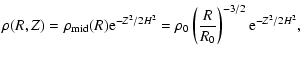
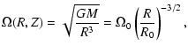
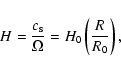
For simplicity and computational reasons we define the initial disc structure using straight-forward analytic functions. The equation of state is locally isothermal: the sound speed,
.
For simplicity and computational reasons we define the initial disc structure using straight-forward analytic functions. The equation of state is locally isothermal: the sound speed, ![]() ,
only depends on R and is constant in time. Both
,
only depends on R and is constant in time. Both ![]() and the disc midplane gas density,
and the disc midplane gas density,
![]() ,
obey power laws
,
obey power laws
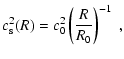
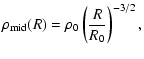
where c0 and
 |
(3) | ||
 |
(4) |
in which
 |
(5) |
where
2.3 Integrated quantities
The density distribution can be used to work out the surface density of the disc:
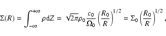
where the second relation serves as a definition for
 |
(7) |
where we have assumed
2.4 Dust size
In this paper, we shall study the effect of MHD turbulence on the
dust. Gas affects solid body dynamics through the drag force it exerts
on the dust particles. In the Epstein regime we are interested in,
this force
![]() takes the simple form
takes the simple form
 |
(9) |
where
 |
(10) |
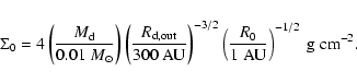
A relevant dimensionless parameter in the problem is the quantity
 |
(11) |
where the parameter
 |
(12) |
Using this expression along with Eq. (8), it is possible to express the dust size in term of
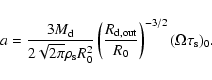
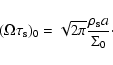
2.5 Converting to physical units
Equations (8) and (13) can be used to
convert the dimensionless quantities describing the problem into
physical quantities. When doing so, the numerical simulations we
will describe in
Sect. 4 should be thought of as covering a small
fraction of the total disc, going from
![]() to an outer radius
to an outer radius
![]() .
.
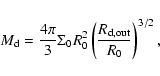
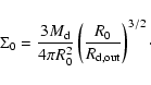
The dimensionless parameters describing the disc and dust particles,
and the results of the numerical simulations presented below, can
be rescaled to any physical system upon specifying the disc mass,
the outer radius of the disc,
and the value of R0 (in astronomical units).
For example, the disc surface density
![]() can be written as
can be written as
Likewise, taking
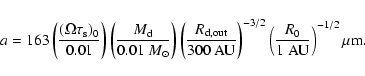
In Sect. 4, we will describe the results of three simulations. They are characterized by
3 Dust settling in turbulent discs
As pointed out in the introduction, a steady state is reached in a turbulent protoplanetary disc in which turbulent fluctuations oppose and balance against dust settling. In this section, we describe three approaches that can be used to model the vertical profile of the dust density.
3.1 A Gaussian profile
The simplest approach, and one that is commonly used when attempting
to interpret observations (Pinte et al. 2008),
is to assume that the dust density
follows a Gaussian distribution, as the gas does, but with a
different vertical scale-height ![]() :
:
 |
(16) |
where
3.2 Turbulence as a diffusive process
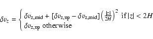
A more physical approach is to describe the transport of the dust particles by the turbulent fluctuations as a diffusion process. This has been used commonly in the literature (Dullemond & Dominik 2004). In this approach, the vertical evolution of the dust density can be described by the following partial differential equation (Dubrulle et al. 1995; Schräpler & Henning 2004):
![\begin{displaymath}\frac{\partial \rho_{\rm d}}{\partial t}-\frac{\partial}{\par...
...\partial z} \left( \frac{\rho_{\rm d}}{\rho} \right)
\right],
\end{displaymath}](/articles/aa/full_html/2009/12/aa11220-08/img67.gif)
where
The vertical integration of the last equation requires the knowledge of the diffusion coefficient as a function of z. The simplest solution is to assume that it is constant. This is the approach described in the following subsection, while in Sect. 3.2.2 we outline a possible alternative.
3.2.1 A constant diffusion coefficient
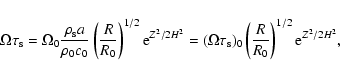
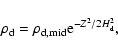
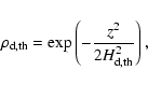
When the dust diffusion coefficient D is constant,
Eq. (18) can be integrated to give
![\begin{displaymath}\rho_{\rm d}=\rho_{\rm d,mid}
\exp \left[-\frac{(\Omega\tau_{...
...ft(\frac{Z^2}{2H^2}\right)-1\right) - \frac{Z^2}{2H^2} \right]
\end{displaymath}](/articles/aa/full_html/2009/12/aa11220-08/img70.gif)
where
A common practice in this context is to express ![]() in units of the standard
in units of the standard ![]() parameter introduced by
Shakura & Sunyaev (1973).
parameter introduced by
Shakura & Sunyaev (1973). ![]() is then written as follows
(Schräpler & Henning 2004; Dullemond & Dominik 2004):
is then written as follows
(Schräpler & Henning 2004; Dullemond & Dominik 2004):
where Sc is the Schmidt number. In zero net flux MHD turbulence, the Schmidt number has been measured to be of order unity in local simulations of unstratified (Johansen et al. 2006b; Johansen & Klahr 2005) or stratified discs (Ilgner & Nelson 2008; Fromang & Papaloizou 2006). In the present paper, we will tune the Schmidt number in order to obtain the best agreement with the numerical simulations.
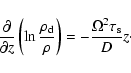
3.2.2 A vertically varying diffusion coefficient
Dust particles are diffused away from the disc midplane by the
turbulent velocity fluctuations.
Thus, the dust diffusion coefficient is intimately linked
to the turbulence properties and particularly to the gas velocity
fluctuations. It would then seem natural for D to be constant in
space if the turbulence was homogeneous. However, because of the
vertical stratification, MHD turbulence is not homogeneous in
protoplanetary discs and it is very likely that D varies with Z at
a given radius (even in the absence of a dead zone).
Using local vertically stratified simulations of the
MRI, Fromang & Papaloizou (2006) showed that the following
simple expression gives a fairly good estimate to the numerically
derived diffusion coefficient:

In this equation,
Of course, the drawback of this approach is that it becomes impossible to explicitly integrated Eq. (18). We cannot provide an analytical expression for the vertical profile of the dust density and shall rely on a numerical integration once the vertical profile for D is extracted from the numerical simulations.
4 Numerical simulations
4.1 Set-up
![\begin{figure}
\par\includegraphics[scale=0.4]{1220f1.ps}\includegraphics[scale=0.4]{1220f2.ps}
\end{figure}](/articles/aa/full_html/2009/12/aa11220-08/img78.gif) |
Figure 1:
Snapshots of the gas density ( left panel) and the dust
density ( right panel) at t=600 for the case
|
| Open with DEXTER | |
The simulations presented in this paper are run using the code GLOBAL (Hawley & Stone 1995), which solves the ideal MHD equations using a spherical coordinate system as defined in Sect. 2.1. The set-up we used is exactly that of model S5 in Fromang & Nelson (2006). Here, we describe it only briefly.
At the start of the simulation, the disc model presented in
Sect. 2.2 is initialized on the grid. The units are
such that GM=1, c0=0.1 and ![]() (i.e. H/R=0.1 throughout
the disc). The computational domain covers the range
(i.e. H/R=0.1 throughout
the disc). The computational domain covers the range
![]() to
to
![]() in radius and the interval
in radius and the interval ![]() in
in ![]() .
In the
.
In the ![]() -direction, the grid extends to
4.3 scale-heights on both sides of
the disc equatorial plane. The resolution for each simulation is
-direction, the grid extends to
4.3 scale-heights on both sides of
the disc equatorial plane. The resolution for each simulation is
![]() .
Following
Fromang & Nelson (2006), a weak toroidal magnetic field is added to
the disc, and small random velocity perturbations are also
imposed. Time is measured in units of the
orbital period at the inner edge of the computational domain in the
following sections.
.
Following
Fromang & Nelson (2006), a weak toroidal magnetic field is added to
the disc, and small random velocity perturbations are also
imposed. Time is measured in units of the
orbital period at the inner edge of the computational domain in the
following sections.
Because of the MRI, the presence of a weak magnetic field, together
with the velocity perturbations,
begins to drive MHD turbulence and angular momentum
transport through the disc within a few orbits of the simulations
starting. To reach a meaningful quasi steady state, however, the model is first evolved for 430 orbits without dust particles. At that stage, the gas density is reset to its
initial distribution and dust
particles are introduced such that the dust-to-gas ratio is uniform
through the computational domain (note that we neglect the back
reaction of the solids onto the gas, so that the value of this ratio
has no physical consequences). We ran three simulations for
three different particle
sizes. The three values of
![]() associated with these
sizes are 10-2, 10-3 and 10-4. All the simulations are
further integrated for about 200 orbits until the dust distribution
itself reaches a steady state in which gravitational settling is
balanced by turbulent diffusion. Examples of the disc structure
at the end of such a run are illustrated in
Fig. 1. Two snapshots of the gas (left panel)
and dust (right panel) density in the (R,Z) plane are
shown in the case
associated with these
sizes are 10-2, 10-3 and 10-4. All the simulations are
further integrated for about 200 orbits until the dust distribution
itself reaches a steady state in which gravitational settling is
balanced by turbulent diffusion. Examples of the disc structure
at the end of such a run are illustrated in
Fig. 1. Two snapshots of the gas (left panel)
and dust (right panel) density in the (R,Z) plane are
shown in the case
![]() at time t=600. The dust
disc appears thinner than the gas disc, indicating that
significant settling has occurred.
at time t=600. The dust
disc appears thinner than the gas disc, indicating that
significant settling has occurred.
In the following subsections, we will compare the dust distributions we obtained for the different sizes to the models described in Sect. 3. To do so, all relevant physical quantities will be averaged in time between t=550 and t=600 using 50 snapshots so that they become statistically significant. We first start by describing the relevant properties of the turbulence that result from this procedure before concentrating on the degree of settling as a function of size.
4.2 Turbulence properties
![\begin{figure}
\par\includegraphics[scale=0.45]{1220f3.ps}
\end{figure}](/articles/aa/full_html/2009/12/aa11220-08/img87.gif) |
Figure 2:
Radial profile of |
| Open with DEXTER | |
![\begin{figure}
\par\includegraphics[scale=0.45]{1220f4.ps}
\end{figure}](/articles/aa/full_html/2009/12/aa11220-08/img88.gif) |
Figure 3:
Radial profile of |
| Open with DEXTER | |
![\begin{figure}
\par\includegraphics[scale=0.5]{1220f5.ps}
\end{figure}](/articles/aa/full_html/2009/12/aa11220-08/img89.gif) |
Figure 4:
Vertical profile of the vertical velocity fluctuations (in units of
the speed of sound) for the model having
|
| Open with DEXTER | |
![\begin{figure}
\par\includegraphics[scale=0.45]{1220f6.ps}
\end{figure}](/articles/aa/full_html/2009/12/aa11220-08/img90.gif) |
Figure 5:
Time variation of the correlation function of the vertical
velocity fluctuations in the disc midplane ( solid line) and in the disc corona ( dashed line). The dotted lines represent functions decreasing exponentially toward zero with typical times
|
| Open with DEXTER | |
The first relevant property of the turbulence is the vertically averaged angular momentum transport it generates. It is commonly measured using the parameter ![]() .
Following
Fromang & Nelson (2006), we calculated
.
Following
Fromang & Nelson (2006), we calculated ![]() as a function of radius according to
as a function of radius according to
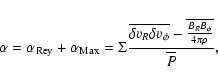
where
In this paper, we present three simulations for different
particle sizes. Because these simulations were obtained under
different computing set-ups (i.e. using different numbers of
CPUs), the details of the turbulent flows
differ from one run to another. This is simply due to the chaotic
nature of turbulence (Winters et al. 2003).
However, the statistical properties of the
turbulence are similar. This is shown in Fig. 3
where we compare the radial profile of ![]() for the models
for the models
![]() (solid line), 0.001 (dotted line) and
0.0001 (dashed line). For each case, the curves are averaged
in time between t=550 and t=600. Figure 3
demonstrates that we obtain very similar values of
(solid line), 0.001 (dotted line) and
0.0001 (dashed line). For each case, the curves are averaged
in time between t=550 and t=600. Figure 3
demonstrates that we obtain very similar values of ![]() in the
different simulations. Thus it is meaningful to compare the dust
distributions in the three different models.
in the
different simulations. Thus it is meaningful to compare the dust
distributions in the three different models.
As explained in Sect. 3.2.2, the vertical velocity
fluctuations and the correlation timescale of the turbulence are also
of importance in affecting the diffusion of solid particles. In
Fig. 4, we show the vertical profile of the
vertical velocity fluctuations at R=2.93, normalized by the speed of
sound and averaged in time between t=550 and t=600 for the
models
![]() (solid line), 0.001 (dotted
line) and 0.0001 (dashed line). Again the results are very
similar for each model and in agreement with those of
Fromang & Nelson (2006): the average
(solid line), 0.001 (dotted
line) and 0.0001 (dashed line). Again the results are very
similar for each model and in agreement with those of
Fromang & Nelson (2006): the average
![]() is of order 5% of the speed
of sound in the disc midplane before rising up to values of the order
of 20-30% in the disc corona, where weak shocks develop
in locations where convergent flow speeds exceed the sound speed
(Fromang & Nelson 2006).
These supersonic turbulent motions are driven by magnetic
stresses in regions where the Alfvén speed exceeds the sound speed.
Figure 4 shows that
is of order 5% of the speed
of sound in the disc midplane before rising up to values of the order
of 20-30% in the disc corona, where weak shocks develop
in locations where convergent flow speeds exceed the sound speed
(Fromang & Nelson 2006).
These supersonic turbulent motions are driven by magnetic
stresses in regions where the Alfvén speed exceeds the sound speed.
Figure 4 shows that
![]() varies by a
factor of about 5 between the disc midplane and its corona.
varies by a
factor of about 5 between the disc midplane and its corona.
As expressed by Eq. (21), the dust diffusion coefficient also
depends on the turbulence correlation timescale
![]() .
Although D depends on
the value of
.
Although D depends on
the value of
![]() to the first power only,
while it depends on the velocity fluctuations to the
second power, vertical variations in the correlation timescale could
still affect the numerical estimate of the diffusion
coefficient. We thus calculated the value of
to the first power only,
while it depends on the velocity fluctuations to the
second power, vertical variations in the correlation timescale could
still affect the numerical estimate of the diffusion
coefficient. We thus calculated the value of
![]() at two
locations, one in the disc midplane and the other in the disc
corona. Following Fromang & Papaloizou (2006),
at two
locations, one in the disc midplane and the other in the disc
corona. Following Fromang & Papaloizou (2006),
![]() can be evaluated by monitoring the time variation of the function
can be evaluated by monitoring the time variation of the function
| (23) |
where
![\begin{figure}
\par\includegraphics[width=6cm,clip]{1220f7.ps}\includegraphics[w...
...6cm,clip]{1220f8.ps}\includegraphics[width=6cm,clip]{1220f9.ps}
\par\end{figure}](/articles/aa/full_html/2009/12/aa11220-08/img109.gif) |
Figure 6:
Dust density distribution in the (R,Z) plane in the numerical simulation for the model having
|
| Open with DEXTER | |
![\begin{figure}
\par\includegraphics[scale=0.3,clip]{1220f10.ps}\includegraphics[...
...=0.3,clip]{1220f11.ps}\includegraphics[scale=0.3,clip]{1220f12.ps}
\end{figure}](/articles/aa/full_html/2009/12/aa11220-08/img114.gif) |
Figure 7:
Dust density distribution in the (R,Z) plane computed
by fitting a Gaussian vertical profile to the simulation data (azimuthally and time averaged) at each radii. As is the case for Fig. 6, the left, middle and right panels
respectively correspond to
|
| Open with DEXTER | |
4.3 Dust spatial distribution
![\begin{figure}
\par\includegraphics[scale=0.3]{1220f13.ps}\includegraphics[scale=0.3]{1220f14.ps}\includegraphics[scale=0.3]{1220f15.ps}
\end{figure}](/articles/aa/full_html/2009/12/aa11220-08/img115.gif) |
Figure 8: Same as Fig. 7 using the model that assumes D=constant. |
| Open with DEXTER | |
![\begin{figure}
\par\includegraphics[scale=0.3]{1220f16.ps}\includegraphics[scale=0.3]{1220f17.ps}\includegraphics[scale=0.3]{1220f18.ps}
\par\end{figure}](/articles/aa/full_html/2009/12/aa11220-08/img116.gif) |
Figure 9:
Same as Fig. 7 using the model that assumes
|
| Open with DEXTER | |
For the three simulations we performed, we averaged the dust density
in azimuth and over time between t=550 and t=600 orbits.
The spatial distributions we obtained using this procedure
are shown in Fig. 6 for the models having
![]() (left panel), 0.001 (middle panel) and
0.0001 (right panel). Note that the radial extent of the
snapshots is limited to
(left panel), 0.001 (middle panel) and
0.0001 (right panel). Note that the radial extent of the
snapshots is limited to ![]() .
At larger radii, the outer buffer
region we use (see Fromang & Nelson 2006) starts to affect the dust
distribution. As expected, the smaller the dust
particle sizes, the thicker the dust disc. This is simply because
smaller particles are better coupled to the gas and can thus be lifted
further away from the disc midplane by the turbulence before they
decouple from the gas. The left panel also shows some sign of the dust
disc flattening at large radii. This is simply because the strength
of the turbulence, as measured for example by the parameter
.
At larger radii, the outer buffer
region we use (see Fromang & Nelson 2006) starts to affect the dust
distribution. As expected, the smaller the dust
particle sizes, the thicker the dust disc. This is simply because
smaller particles are better coupled to the gas and can thus be lifted
further away from the disc midplane by the turbulence before they
decouple from the gas. The left panel also shows some sign of the dust
disc flattening at large radii. This is simply because the strength
of the turbulence, as measured for example by the parameter ![]() ,
decreases at large radii, as seen in Figs. 2 and 3. It should not be confused with the apparent
dust disc flattening identified by Dullemond & Dominik (2004),
which occurs because of self-shadowing in the presence of
weak turbulence. Finally, Fig. 6 also highlights one
of the limitations of our work: with the set-up of the simulations
presented in this
paper, we cannot easily extend our parameter survey to smaller
particles. Indeed, when
,
decreases at large radii, as seen in Figs. 2 and 3. It should not be confused with the apparent
dust disc flattening identified by Dullemond & Dominik (2004),
which occurs because of self-shadowing in the presence of
weak turbulence. Finally, Fig. 6 also highlights one
of the limitations of our work: with the set-up of the simulations
presented in this
paper, we cannot easily extend our parameter survey to smaller
particles. Indeed, when
![]() ,
the dust disc
already covers almost the entire computational domain
in the vertical direction. Reducing
further the size of the dust particles would require an increase in
the size of the computational domain in the meridional region for the
decoupling between gas and dust to occur within the computational
grid. This would require an increase in the computing time required
for a simulation performed with the same resolution.
This will soon become possible as
computational resources improve, but is currently very
challenging.
,
the dust disc
already covers almost the entire computational domain
in the vertical direction. Reducing
further the size of the dust particles would require an increase in
the size of the computational domain in the meridional region for the
decoupling between gas and dust to occur within the computational
grid. This would require an increase in the computing time required
for a simulation performed with the same resolution.
This will soon become possible as
computational resources improve, but is currently very
challenging.
![\begin{figure}
\par\includegraphics[width=8.05cm,clip]{1220f19.ps}\par\includegr...
...ip]{1220f20.ps}\par\includegraphics[width=8cm,clip]{1220f21.ps}
\par\end{figure}](/articles/aa/full_html/2009/12/aa11220-08/img118.gif) |
Figure 10:
Vertical profiles of the dust density, radially averaged
between R=3 and R=5. As shown by the legend displayed on
the upper panel, the different curves (normalized by their
midplane values) were obtained using the numerical simulations ( solid line), by fitting a Gaussian profile to the simulation data ( dotted-dashed line), using a constant
turbulent diffusion coefficient ( dashed line) and a vertically
varying diffusion coefficient ( dotted line). The upper, middle
and lower panels respectively correspond to
|
| Open with DEXTER | |
To compare these results with the models presented in Sects. 3.1, 3.2.1 and 3.2.2, we computed the expected 2D dust distribution that each of them would predict. In doing so, we used the same disc and dust parameters as in the simulations.
- -
- For the first model (presented in Sect. 3.1), we fitted a Gaussian profile to the vertical profile of the dust density at each radius. This was done by performing a least squares fit to the dust density profile over the entire vertical extent of the disc. The resulting spatial distributions are plotted in Fig. 7 using the same color table and spatial domain as in Fig. 6.
- -
- For the second model (presented in Sect. 3.2.1), we used Eq. (19)
to calculate the vertical profile of the dust density at each
radius. The numerical value of the dimensionless diffusion coefficient
 at each radius was calculated using
Eq. (20) in which we plugged the value of
at each radius was calculated using
Eq. (20) in which we plugged the value of  calculated according to Eq. (22). We used
 as this
value turns out to provide the best fit to the simulations. Being of
order unity, it is also in agreement with the results of previous
local numerical simulations (Johansen et al. 2006b; Fromang & Papaloizou 2006; Johansen & Klahr 2005). The resulting spatial distributions of the dust density are plotted in Fig. 8.
as this
value turns out to provide the best fit to the simulations. Being of
order unity, it is also in agreement with the results of previous
local numerical simulations (Johansen et al. 2006b; Fromang & Papaloizou 2006; Johansen & Klahr 2005). The resulting spatial distributions of the dust density are plotted in Fig. 8.
- -
- For the third model (presented in Sect. 3.2.2), we integrated Eq. (18) numerically, using at each disc altitude the estimate for the diffusion coefficient D provided by Eq. (21). In this equation, we used the azimuthally and time averaged vertical profile of the vertical velocity fluctuations at each radius (as shown in Fig. 4 for the special case R=2.93) and the correlation time
 orbit as explained in Sect. 4.2. The resulting spatial distributions of the dust density are plotted in Fig. 9.
On the other hand, models having smaller dust sizes, i.e.
![]() and 0.0001, show differences between the different
approaches. The Gaussian fit to the simulations always overestimates
the dust density in the disc corona (
and 0.0001, show differences between the different
approaches. The Gaussian fit to the simulations always overestimates
the dust density in the disc corona (
![]() ),
showing that in general the vertical profile of the dust density
distribution is non Gaussian. On the other hand, the model
having a constant diffusion coefficient always underestimates
the dust density in the disc corona. Only the model taking the
vertical variation of the diffusion coefficient into account gives
a satisfactory fit to the simulations, especially in the disc upper
layers.
),
showing that in general the vertical profile of the dust density
distribution is non Gaussian. On the other hand, the model
having a constant diffusion coefficient always underestimates
the dust density in the disc corona. Only the model taking the
vertical variation of the diffusion coefficient into account gives
a satisfactory fit to the simulations, especially in the disc upper
layers.
These differences can be made more quantitative by comparing the
vertical profile of the dust density between the simulations and the
models. This is done in
Fig. 10. The upper panel gathers the results corresponding
to the case
![]() ,
the middle panel shows results
obtained when
,
the middle panel shows results
obtained when
![]() .
Finally, the lower panel shows
results obtained when
.
Finally, the lower panel shows
results obtained when
![]() .
In each panel, the
solid curves plot the vertical profile of the dust density obtained in
the MHD simulation by temporally, azimuthally and radially
averaging the results.
The radial averaging is performed over the range
.
In each panel, the
solid curves plot the vertical profile of the dust density obtained in
the MHD simulation by temporally, azimuthally and radially
averaging the results.
The radial averaging is performed over the range
![]() .
The
dot-dashed, dashed and dotted curves, respectively, correspond to
the model using a Gaussian fit to the data, a constant diffusion
coefficient and a vertically varying diffusion coefficient. Again, the
upper panel demonstrates the good agreement between all approaches in
the case of large particles, as the curves used to represent the
results of the different models are almost undistiguishable on that
plot. It also provides, however, a first hint that the Gaussian
fit increasingly overestimates the dust density as one moves
away from the midplane, even for these larger particles.
The middle and lower panels confirm these results and
show that the model having a vertically varying diffusion
coefficient provides in general the best fit to the data in the disc
corona. For example, in the case
.
The
dot-dashed, dashed and dotted curves, respectively, correspond to
the model using a Gaussian fit to the data, a constant diffusion
coefficient and a vertically varying diffusion coefficient. Again, the
upper panel demonstrates the good agreement between all approaches in
the case of large particles, as the curves used to represent the
results of the different models are almost undistiguishable on that
plot. It also provides, however, a first hint that the Gaussian
fit increasingly overestimates the dust density as one moves
away from the midplane, even for these larger particles.
The middle and lower panels confirm these results and
show that the model having a vertically varying diffusion
coefficient provides in general the best fit to the data in the disc
corona. For example, in the case
![]() ,
the three
models give a good fit to the data for
,
the three
models give a good fit to the data for ![]() .
For
.
For ![]() ,
the Gaussian fit to the data overestimates the density obtained in the
simulations (their ratio is about 103 at Z=3H) and the model
having a constant diffusion coefficient underestimates that density
(the ratio at 3H is in excess of 106). The agreement between the
simulations and the model having a vertically varying diffusion
coefficient is better as the ratio between the predicted and observed
dust densities is always bounded by 10, despite the fact that the dust density
itself varies by more than 6 orders of magnitude. It is interesting to
point out, though, that the value of the density predicted by this
model close to the equatorial plane seems to significantly
underestimate the results of the simulations. This is most likely
because the correlation timescale we used in calculating the diffusion
coefficient underestimates the midplane correlation timescale of the
turbulence (see Sect. 4.2). Using a varying
correlation timescale would certainly
further improve the agreement with the numerical simulations, but such
a level of refinement is probably meaningless given the other
approximations involved in the simulations themselves.
As shown in Fig. 10, the situation is similar in the case
,
the Gaussian fit to the data overestimates the density obtained in the
simulations (their ratio is about 103 at Z=3H) and the model
having a constant diffusion coefficient underestimates that density
(the ratio at 3H is in excess of 106). The agreement between the
simulations and the model having a vertically varying diffusion
coefficient is better as the ratio between the predicted and observed
dust densities is always bounded by 10, despite the fact that the dust density
itself varies by more than 6 orders of magnitude. It is interesting to
point out, though, that the value of the density predicted by this
model close to the equatorial plane seems to significantly
underestimate the results of the simulations. This is most likely
because the correlation timescale we used in calculating the diffusion
coefficient underestimates the midplane correlation timescale of the
turbulence (see Sect. 4.2). Using a varying
correlation timescale would certainly
further improve the agreement with the numerical simulations, but such
a level of refinement is probably meaningless given the other
approximations involved in the simulations themselves.
As shown in Fig. 10, the situation is similar in the case
![]() :
the best fit to the numerical simulations is
provided by the final and more elaborate model. Indeed, at
:
the best fit to the numerical simulations is
provided by the final and more elaborate model. Indeed, at
![]() ,
the dust density predicted by the model with a constant
diffusion coefficient starts to underestimate significantly the
results of the numerical simulations. Above Z=3H, the difference
becomes enormous, as in the case
,
the dust density predicted by the model with a constant
diffusion coefficient starts to underestimate significantly the
results of the numerical simulations. Above Z=3H, the difference
becomes enormous, as in the case
![]() .
The
agreement, however, seems better with the model that uses a Gaussian
fit to the data than in the case
.
The
agreement, however, seems better with the model that uses a Gaussian
fit to the data than in the case
![]() .
The Gaussian
fit indeed gives a good fit up to Z=3H. This apparent agreement
would most probably break
down for
.
The Gaussian
fit indeed gives a good fit up to Z=3H. This apparent agreement
would most probably break
down for
![]() ,
as the ratio with the simulated densities is
already greater than two orders of magnitude at Z=4H and increases
with increasing Z.
,
as the ratio with the simulated densities is
already greater than two orders of magnitude at Z=4H and increases
with increasing Z.
5 Discussion and conclusions
In this paper, we have studied dust settling in turbulent protoplanetary discs using global MHD numerical simulations performed with the code GLOBAL using spherical coordinates. In this section, we summarize our main findings and discuss the limitations and future prospects of our work.
5.1 Dust density vertical profile
![\begin{figure}
\par\includegraphics[scale=0.5]{1220f22.ps}
\par\end{figure}](/articles/aa/full_html/2009/12/aa11220-08/img128.gif) |
Figure 11:
This figure compares the dust density vertical profile (shown
with a solid line), in the case
|
| Open with DEXTER | |
![\begin{figure}
\par\includegraphics[scale=0.5]{1220f23.ps}
\end{figure}](/articles/aa/full_html/2009/12/aa11220-08/img129.gif) |
Figure 12:
Dust disc scale-heights obtained through a Gaussian fit to the
data are represented by the diamonds as a function of
|
| Open with DEXTER | |
The first point that emerges is that Gaussian profiles
fail badly to reproduce the data extracted from the
simulations. This point is further illustrated by
Fig. 11 where we compare the dust profile in
the case
![]() (solid line) with a
set of Gaussian profiles (dotted lines) computed according to
the following equation,
(solid line) with a
set of Gaussian profiles (dotted lines) computed according to
the following equation,
 |
(24) |
in which we used the values
Nevertheless, in order to compare with results published previously
in the literature, we measured the dust disc scale-height
in our simulations using such a fit. We found
![]() ,
0.84
and 0.40, respectively, for
,
0.84
and 0.40, respectively, for
![]() ,
0.001 and
0.01. The variation of
,
0.001 and
0.01. The variation of
![]() as a function of
as a function of
![]() is shown by the diamonds in Fig. 12. The dotted line
displays the function
is shown by the diamonds in Fig. 12. The dotted line
displays the function
 |
(25) |
which is the best fit to the data. Therefore, if we were to analyse our simulations assuming that the dust density is Gaussian, we would obtain
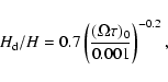
5.2 The Schmidt number
The second result that emerges from our work is that a model having a
constant diffusion coefficient increasingly underestimates the dust
density as the particle size a is decreased. In other words, the
vertically averaged dust diffusion coefficient decreases with a. This is not unexpected, since the Schmidt number introduced in
Sect. 3.2.1 is known to be an increasing function of
![]() (Youdin & Lithwick 2007; Cuzzi et al. 1993; Schräpler & Henning 2004). It is
unclear, however, whether such studies,
which assume homogeneous Kolmogorov-like turbulence,
are applicable to the highly magnetised flow of the corona. This is why we
did not attempt to make a direct comparison between our results and
these theories. For the sake of completeness, it is nevertheless
instructive to report here the vertically averaged Schmidt number we
measured in each case. As described above,
Sc=1.5 already
provides a good fit of
the dust density in the case
(Youdin & Lithwick 2007; Cuzzi et al. 1993; Schräpler & Henning 2004). It is
unclear, however, whether such studies,
which assume homogeneous Kolmogorov-like turbulence,
are applicable to the highly magnetised flow of the corona. This is why we
did not attempt to make a direct comparison between our results and
these theories. For the sake of completeness, it is nevertheless
instructive to report here the vertically averaged Schmidt number we
measured in each case. As described above,
Sc=1.5 already
provides a good fit of
the dust density in the case
![]() .
For the cases
.
For the cases
![]() and 10-4, we found that the vertically
averaged Schmidt numbers that best fit the data are respectively
Sc=0.4 and
Sc=0.03
and 10-4, we found that the vertically
averaged Schmidt numbers that best fit the data are respectively
Sc=0.4 and
Sc=0.03![]() . Although they indicate a scaling with
. Although they indicate a scaling with
![]() close to linear, these results are not necessary in
disagreement with the result of Youdin & Lithwick (2007), who found a
quadratic scaling, because of the vertical average we made when doing
such measurements. Note also that these fairly low values of the
Schmidt number indicate that turbulent diffusion of the smallest
dust particles can be much more efficient than angular momentum
transport. This difference originates from their different physical
origin: angular momentum is transported
radially by the Maxwell and Reynolds stresses while
dust diffuses away from the disc midplane because of the vertical velocity
fluctuations of the gas. The former quantities decrease as one
moves away from the disc midplane
(see Fromang & Nelson 2006; Miller & Stone 2000) while the latter
quantity increases away from the disc midplane. This means that angular
momentum is inefficiently transported in the disc corona while small
dust particles are efficiently diffused at the same location. As a
consequence, the Schmidt number (i.e. the ratio of both diffusion
coefficients) is much smaller than unity
for the smallest of our particles.
close to linear, these results are not necessary in
disagreement with the result of Youdin & Lithwick (2007), who found a
quadratic scaling, because of the vertical average we made when doing
such measurements. Note also that these fairly low values of the
Schmidt number indicate that turbulent diffusion of the smallest
dust particles can be much more efficient than angular momentum
transport. This difference originates from their different physical
origin: angular momentum is transported
radially by the Maxwell and Reynolds stresses while
dust diffuses away from the disc midplane because of the vertical velocity
fluctuations of the gas. The former quantities decrease as one
moves away from the disc midplane
(see Fromang & Nelson 2006; Miller & Stone 2000) while the latter
quantity increases away from the disc midplane. This means that angular
momentum is inefficiently transported in the disc corona while small
dust particles are efficiently diffused at the same location. As a
consequence, the Schmidt number (i.e. the ratio of both diffusion
coefficients) is much smaller than unity
for the smallest of our particles.
5.3 A toy model
![\begin{figure}
\par\includegraphics[scale=0.46]{1220f24.ps}\par\includegraphics[scale=0.46]{1220f25.ps}
\par\end{figure}](/articles/aa/full_html/2009/12/aa11220-08/img143.gif) |
Figure 13:
Comparison between the dust density vertical profile (shown
in both panels with the solid line) in the case
|
| Open with DEXTER | |
The main result of this paper is the construction of a simple model that gives a reasonable fit to the simulations. In this model, the dust particles are diffused away by turbulence with a diffusion coefficient that scales with the square of the turbulent velocity fluctuations. Accordingly, it should be possible in principle to extract the vertical profile of the velocity fluctuations from the dust density vertical profile. This is, however, an inversion problem. As such, it is susceptible to being degenerate and we shall see in this section that this is indeed the case.
The relevant question to ask in this context is the following:
provided we are able to measure the dust density vertical profile,
what is it mostly sensitive to? Can we hope to constrain the velocity
fluctuations in the disc midplane or is it mostly a consequence of
the amplitude of the fluctuations in the upper layers. To answer that
question, we designed the following toy model: guided by the
vertical profile of the velocity fluctuation amplitudes
shown in Fig. 4, we
considered the following analytic vertical profile for the
velocity fluctuations:
where
The implications of these results are twofold. First, the
simple toy model described by Eq. (26) would be
suitable to use when trying to fit the observations as it reproduces the
numerical data fairly well if we choose the values
![]() and
and
![]() ,
compatible with
the simulations. But these results
also show that such a fit would only provide sensitive information
about the turbulent velocity fluctuations in the disc upper layers.
The physical reason for this
last point is that such a fit is mostly sensitive to the
properties of the region where the gas and dust decouple. For the small
particles studied in this paper (and observed using the Spitzer
telescope), this region turns out to lie
in the disc upper layers. When observing larger particles at longer
wavelengths (for example with ALMA), it will become possible to constrain
the turbulent velocity fluctuations of the disc closer to the
midplane as such particles will settle and decouple deeper in the disc.
,
compatible with
the simulations. But these results
also show that such a fit would only provide sensitive information
about the turbulent velocity fluctuations in the disc upper layers.
The physical reason for this
last point is that such a fit is mostly sensitive to the
properties of the region where the gas and dust decouple. For the small
particles studied in this paper (and observed using the Spitzer
telescope), this region turns out to lie
in the disc upper layers. When observing larger particles at longer
wavelengths (for example with ALMA), it will become possible to constrain
the turbulent velocity fluctuations of the disc closer to the
midplane as such particles will settle and decouple deeper in the disc.
5.4 Limitations and future prospects
Of course, there are strong limitations to our work due to the
complex and CPU-intensive nature of global simulations
of protoplanetary discs. On the
purely numerical side, the limited resolution we used is of course an
issue, as was pointed recently in a number of studies
(Simon et al. 2008; Fromang & Papaloizou 2007). Proper simulations should
include explicitly microscopic diffusion coefficients (viscosity and
resistivity), as the latter have been shown to be important in
determining the saturation level of the turbulence
(Lesur & Longaretti 2007; Fromang et al. 2007). However, the resolutions
required to include these processes in global simulations are currently out of
reach and one must instead
rely on the subgrid model provided by numerical dissipation to carry
out global numerical simulations. On a more physical side, there are
also limitations due to the simple disc model we used. The locally
isothermal equation of state we used is not appropriate for the disc inner
parts that we are simulating as the gas there is optically thick.
This could have numerous effects. For example, Dullemond (2002) and
D'Alessio et al. (1998) report a temperature increase in the inner disc
upper layers. Such an increase would strengthen the coupling between
gas and grains in the disc corona (through
a decrease in the local value of the parameter
![]() ). This would cause small particles to settle less than
reported in this paper and could change the relationship between
). This would cause small particles to settle less than
reported in this paper and could change the relationship between ![]() and a. Obviously, the significance of the comparison we tentatively
made between our simulations and the observations of
Pinte et al. (2008) should be taken with care.
Another topic of concern in our simulations is the
assumption of ideal MHD. It is indeed well known that protoplanetary
discs are so poorly
ionized because of their large densities and low temperatures that parts
of the flow, refered to as dead zones, remain laminar
(Gammie 1996). We completely ignored the effects of dead zones in
the present paper. Clearly, future work should improve
the thermodynamic treatment of the gas, possibly including radiative
transfer and dead zones.
and a. Obviously, the significance of the comparison we tentatively
made between our simulations and the observations of
Pinte et al. (2008) should be taken with care.
Another topic of concern in our simulations is the
assumption of ideal MHD. It is indeed well known that protoplanetary
discs are so poorly
ionized because of their large densities and low temperatures that parts
of the flow, refered to as dead zones, remain laminar
(Gammie 1996). We completely ignored the effects of dead zones in
the present paper. Clearly, future work should improve
the thermodynamic treatment of the gas, possibly including radiative
transfer and dead zones.
Nevertheless, we have shown in this paper that dust observations can be used in principle to constrain the properties of MHD turbulence in discs. We have found that even the simplest simulations provide disagreements with previously used fits and diffusion models because of the nature of disc turbulence. This illustrates even further the need to compare directly observations and numerical simulations. It will be important in the future togenerate a grid of more realistic discs models (varying the disc parameters, including dead zones, flaring discs, non isothermal discs) and produce synthetic observations that could be compared in the next few years with multiwavelengths observations. This comparison would provide diagnostics of disc turbulence, the existence (or not) of dead zones and thus constrain planet formation models. The recent work of Pinte et al. (2008) shows that such multiwavelengths observations are starting to become feasible. When combined with future instruments like Herschel and ALMA, large samples will become available and will provide a wealth of constraints on disc structure and properties when combined with appropriate global numerical simulations of protoplanetary discs.
Acknowledgements
The simulations presented in this paper were performed using the QMUL High Performance Computing Facility purchased under the SRIF initiative. It is a pleasure to acknowledge fruitful discussions with J.-C.Augereau and P.-Y. Longaretti. We also thank an anonymous referee whose comments significantly improved the paper.
References
- Apai, D., Pascucci, I., Bouwman, J., et al. 2005, Science, 310, 834 [NASA ADS] [CrossRef]
- Balbus, S., & Hawley, J. 1991, ApJ, 376, 214 [NASA ADS] [CrossRef]
- Balbus, S., & Hawley, J. 1998, Rev. Mod. Phys., 70, 1 [NASA ADS] [CrossRef]
- Balsara, D. S., Tilley, D. A., Rettig, T., & Brittain, S. A. 2008, ArXiv e-prints (In the text)
- Barrière-Fouchet, L., Gonzalez, J. F., Murray, J. F., Humble, R. J., & Maddison, S. T. 2005, A&A, 443, 185 [NASA ADS] [CrossRef] [EDP Sciences] (In the text)
- Carballido, A., Stone, J. M., & Pringle, J. E. 2005, MNRAS, 358, 1055 [NASA ADS] [CrossRef]
- Carballido, A., Fromang, S., & Papaloizou, J. 2006, MNRAS, 373, 1633 [NASA ADS] [CrossRef]
- Chiang, E. I., & Goldreich, P. 1997, ApJ, 490, 368 [NASA ADS] [CrossRef] (In the text)
- Cuzzi, J. N., Dobrovolskis, A. R., & Champney, J. M. 1993, Icarus, 106, 102 [NASA ADS] [CrossRef]
- D'Alessio, P., Canto, J., Calvet, N., & Lizano, S. 1998, ApJ, 500, 411 [NASA ADS] [CrossRef] (In the text)
- D'Alessio, P., Calvet, N., Hartmann, L., Franco-Hernández, R., & Servín, H. 2006, ApJ, 638, 314 [NASA ADS] [CrossRef] (In the text)
- Dubrulle, B., Morfill, G., & Sterzik, M. 1995, Icarus, 114, 237 [NASA ADS] [CrossRef]
- Dullemond, C. P. 2002, A&A, 395, 853 [NASA ADS] [CrossRef] [EDP Sciences] (In the text)
- Dullemond, C. P., & Dominik, C. 2004, A&A, 421, 1075 [NASA ADS] [CrossRef] [EDP Sciences]
- Dullemond, C. P., & Dominik, C. 2008, A&A, 487, 205 [NASA ADS] [CrossRef] [EDP Sciences]
- Fromang, S., & Nelson, R. 2005, MNRAS, 364, L81 [NASA ADS] (In the text)
- Fromang, S., & Nelson, R. P. 2006, A&A, 457, 343 [NASA ADS] [CrossRef] [EDP Sciences] (In the text)
- Fromang, S., & Papaloizou, J. 2006, A&A, 452, 751 [NASA ADS] [CrossRef] [EDP Sciences]
- Fromang, S., & Papaloizou, J. 2007, A&A, 476, 1113 [NASA ADS] [CrossRef] [EDP Sciences]
- Fromang, S., Papaloizou, J., Lesur, G., & Heinemann, T. 2007, A&A, 476, 1123 [NASA ADS] [CrossRef] [EDP Sciences]
- Furlan, E., Calvet, N., D'Alessio, P., et al. 2005, ApJ, 628, L65 [NASA ADS] [CrossRef]
- Furlan, E., Hartmann, L., Calvet, N., et al. 2006, ApJS, 165, 568 [NASA ADS] [CrossRef]
- Gammie, C. F. 1996, ApJ, 457, 355 [NASA ADS] [CrossRef] (In the text)
- Goldreich, P., & Lynden-Bell, D. 1965, MNRAS, 130, 125 [NASA ADS] (In the text)
- Hawley, J., & Stone, J. 1995, Comput. Phys. Commun., 89, 127 [NASA ADS] [CrossRef] (In the text)
- Ilgner, M., & Nelson, R. P. 2008, A&A, 483, 815 [NASA ADS] [CrossRef] [EDP Sciences]
- Johansen, A., & Klahr, H. 2005, ApJ, 634, 1353 [NASA ADS] [CrossRef]
- Johansen, A., Klahr, H., & Henning, T. 2006a, ApJ, 636, 1121 [NASA ADS] [CrossRef]
- Johansen, A., Klahr, H., & Mee, A. J. 2006b, MNRAS, 370, L71 [NASA ADS]
- Kessler-Silacci, J., Augereau, J.-C., Dullemond, C. P., et al. 2006, ApJ, 639, 275 [NASA ADS] [CrossRef]
- Kessler-Silacci, J. E., Dullemond, C. P., Augereau, J.-C., et al. 2007, ApJ, 659, 680 [NASA ADS] [CrossRef] (In the text)
- Lesur, G., & Longaretti, P.-Y. 2007, MNRAS, 378, 1471 [NASA ADS] [CrossRef]
- Lyra, W., Johansen, A., Klahr, H., & Piskunov, N. 2008, A&A, 479, 883 [NASA ADS] [CrossRef] [EDP Sciences] (In the text)
- Miller, K. A., & Stone, J. M. 2000, ApJ, 534, 398 [NASA ADS] [CrossRef] (In the text)
- Pinte, C., Fouchet, L., Ménard, F., Gonzalez, J.-F., & Duchêne, G. 2007, A&A, 469, 963 [NASA ADS] [CrossRef] [EDP Sciences]
- Pinte, C., Padgett, D. L., Menard, F., et al. 2008, ArXiv e-prints, 808 (In the text)
- Rettig, T., Brittain, S., Simon, T., et al. 2006, ApJ, 646, 342 [NASA ADS] [CrossRef]
- Schräpler, R., & Henning, T. 2004, ApJ, 614, 960 [NASA ADS] [CrossRef]
- Shakura, N. I., & Sunyaev, R. A. 1973, A&A, 24, 337 [NASA ADS] (In the text)
- Sicilia-Aguilar, A., Hartmann, L. W., Watson, D., et al. 2007, ApJ, 659, 1637 [NASA ADS] [CrossRef]
- Simon, J. B., Hawley, J. F., & Beckwith, K. 2008, ArXiv e-prints
- van Boekel, R., Waters, L. B. F. M., Dominik, C., et al. 2003, A&A, 400, L21 [NASA ADS] [CrossRef] [EDP Sciences]
- Weidenschilling, S. J. 1984, Icarus, 60, 553 [NASA ADS] [CrossRef] (In the text)
- Winters, W. F., Balbus, S. A., & Hawley, J. F. 2003, MNRAS, 340, 519 [NASA ADS] [CrossRef] (In the text)
- Youdin, A. N., & Lithwick, Y. 2007, Icarus, 192, 588 [NASA ADS] [CrossRef]
Footnotes
- ...
Sc=0.03
![[*]](/icons/foot_motif.gif)
- The fact that we obtain Schmidt numbers lower than one, in contrast to Cuzzi et al. (1993), Schräpler & Henning (2004) and Youdin & Lithwick (2007) is due to our definition being different to that used in these theoretical studies, as discussed in detail by Youdin & Lithwick (2007).
All Figures
| |
Figure 1:
Snapshots of the gas density ( left panel) and the dust
density ( right panel) at t=600 for the case
|
| Open with DEXTER | |
| In the text | |
| |
Figure 2:
Radial profile of |
| Open with DEXTER | |
| In the text | |
| |
Figure 3:
Radial profile of |
| Open with DEXTER | |
| In the text | |
| |
Figure 4:
Vertical profile of the vertical velocity fluctuations (in units of
the speed of sound) for the model having
|
| Open with DEXTER | |
| In the text | |
| |
Figure 5:
Time variation of the correlation function of the vertical
velocity fluctuations in the disc midplane ( solid line) and in the disc corona ( dashed line). The dotted lines represent functions decreasing exponentially toward zero with typical times
|
| Open with DEXTER | |
| In the text | |
| |
Figure 6:
Dust density distribution in the (R,Z) plane in the numerical simulation for the model having
|
| Open with DEXTER | |
| In the text | |
| |
Figure 7:
Dust density distribution in the (R,Z) plane computed
by fitting a Gaussian vertical profile to the simulation data (azimuthally and time averaged) at each radii. As is the case for Fig. 6, the left, middle and right panels
respectively correspond to
|
| Open with DEXTER | |
| In the text | |
| |
Figure 8: Same as Fig. 7 using the model that assumes D=constant. |
| Open with DEXTER | |
| In the text | |
| |
Figure 9:
Same as Fig. 7 using the model that assumes
|
| Open with DEXTER | |
| In the text | |
| |
Figure 10:
Vertical profiles of the dust density, radially averaged
between R=3 and R=5. As shown by the legend displayed on
the upper panel, the different curves (normalized by their
midplane values) were obtained using the numerical simulations ( solid line), by fitting a Gaussian profile to the simulation data ( dotted-dashed line), using a constant
turbulent diffusion coefficient ( dashed line) and a vertically
varying diffusion coefficient ( dotted line). The upper, middle
and lower panels respectively correspond to
|
| Open with DEXTER | |
| In the text | |
| |
Figure 11:
This figure compares the dust density vertical profile (shown
with a solid line), in the case
|
| Open with DEXTER | |
| In the text | |
| |
Figure 12:
Dust disc scale-heights obtained through a Gaussian fit to the
data are represented by the diamonds as a function of
|
| Open with DEXTER | |
| In the text | |
| |
Figure 13:
Comparison between the dust density vertical profile (shown
in both panels with the solid line) in the case
|
| Open with DEXTER | |
| In the text | |
Copyright ESO 2009
Current usage metrics show cumulative count of Article Views (full-text article views including HTML views, PDF and ePub downloads, according to the available data) and Abstracts Views on Vision4Press platform.
Data correspond to usage on the plateform after 2015. The current usage metrics is available 48-96 hours after online publication and is updated daily on week days.
Initial download of the metrics may take a while.