| Issue |
A&A
Volume 494, Number 3, February II 2009
|
|
|---|---|---|
| Page(s) | 1127 - 1136 | |
| Section | The Sun | |
| DOI | https://doi.org/10.1051/0004-6361:200810437 | |
| Published online | 11 December 2008 | |
Multi-wavelength observations and modelling of a canonical solar flare
C. L. Raftery1,2 - P. T. Gallagher1 - R. O. Milligan2 - J. A. Klimchuk2
1 - Astrophysics Research Group, School of Physics, Trinity College Dublin, Dublin 2, Ireland
2 - Solar Physics Laboratory (Code 671), Heliophysics Science Division, NASA Goddard Space Flight Centre, Greenbelt, MD 20771, USA
Received 20 June 2008 / Accepted 5 December 2008
Abstract
Aims. We investigate the temporal evolution of temperature, emission measure, energy loss, and velocity in a C-class solar flare from both observational and theoretical perspectives.
Methods. The properties of the flare were derived by following the systematic cooling of the plasma through the response functions of a number of instruments - the Reuven Ramaty High Energy Solar Spectroscopic Imager (RHESSI; >5 MK), GOES-12 (5-30 MK), the Transition Region and Coronal Explorer (TRACE 171 Å; 1 MK), and the Coronal Diagnostic Spectrometer (CDS; ![]() 0.03-8 MK). These measurements were studied in combination with simulations from the 0-D enthalpy based thermal evolution of loops (EBTEL) model.
0.03-8 MK). These measurements were studied in combination with simulations from the 0-D enthalpy based thermal evolution of loops (EBTEL) model.
Results. At the flare onset, upflows of ![]() 90 km s-1 and low-level emission were observed in Fe XIX, consistent with pre-flare heating and gentle chromospheric evaporation. During the impulsive phase, upflows of
90 km s-1 and low-level emission were observed in Fe XIX, consistent with pre-flare heating and gentle chromospheric evaporation. During the impulsive phase, upflows of ![]() 80 km s-1 in Fe XIX and simultaneous downflows of
80 km s-1 in Fe XIX and simultaneous downflows of ![]() 20 km s-1 in He I and O V were observed, indicating explosive chromospheric evaporation. The plasma was subsequently found to reach a peak temperature of
20 km s-1 in He I and O V were observed, indicating explosive chromospheric evaporation. The plasma was subsequently found to reach a peak temperature of ![]() 13 MK in approximately 10 min. Using EBTEL, conduction was found to be the dominant loss mechanism during the initial
13 MK in approximately 10 min. Using EBTEL, conduction was found to be the dominant loss mechanism during the initial ![]() 300 s of the decay phase. It was also found to be responsible for driving gentle chromospheric evaporation during this period. As the temperature fell below
300 s of the decay phase. It was also found to be responsible for driving gentle chromospheric evaporation during this period. As the temperature fell below ![]() 8 MK, and for the next
8 MK, and for the next ![]() 4000 s, radiative losses were determined to dominate over conductive losses. The radiative loss phase was accompanied by significant downflows of
4000 s, radiative losses were determined to dominate over conductive losses. The radiative loss phase was accompanied by significant downflows of ![]() 40 km s-1 in O V.
40 km s-1 in O V.
Conclusions. This is the first extensive study of the evolution of a canonical solar flare using both spectroscopic and broad-band instruments in conjunction with a 0-D hydrodynamic model. While our results are in broad agreement with the standard flare model, the simulations suggest that both conductive and non-thermal beam heating play important roles in heating the flare plasma during the impulsive phase of at least this event.
Key words: Sun: flares - hydrodynamics
1 Introduction
The temporal evolution of most solar flares can be divided into two distinct phases. During the impulsive phase temperatures rise to ![]() 10 MK via direct heating below the reconnection site in the corona and/or the process of chromospheric evaporation due to accelerated particles (Kopp & Pneuman 1976). Chromospheric evaporation driven by accelerated particles can be classified in one of two ways: explosive or gentle (Fisher et al. 1985; Milligan et al. 2006a,b). Explosive evaporation occurs when the flux of non-thermal particles impacting the chromosphere is greater than a critical value (
10 MK via direct heating below the reconnection site in the corona and/or the process of chromospheric evaporation due to accelerated particles (Kopp & Pneuman 1976). Chromospheric evaporation driven by accelerated particles can be classified in one of two ways: explosive or gentle (Fisher et al. 1985; Milligan et al. 2006a,b). Explosive evaporation occurs when the flux of non-thermal particles impacting the chromosphere is greater than a critical value (![]()
![]() erg cm-2 s-1) and the chromosphere cannot dissipate the absorbed energy efficiently enough. The plasma is forced to expand into the corona as hot upflows of hundreds of km s-1 and simultaneously into the chromosphere as cooler downflows of tens of km s-1. Beam driven gentle evaporation occurs when the non-thermal flux is less than
erg cm-2 s-1) and the chromosphere cannot dissipate the absorbed energy efficiently enough. The plasma is forced to expand into the corona as hot upflows of hundreds of km s-1 and simultaneously into the chromosphere as cooler downflows of tens of km s-1. Beam driven gentle evaporation occurs when the non-thermal flux is less than ![]() 1010 erg cm-2 s-1. Under these circumstances, the chromospheric response is efficient in radiating the absorbed energy. Gentle evaporation can also be driven by a downward heat flux from the corona. In both cases, plasma rises slowly (tens of km s-1) upwards into the loop. Once the energy release has ceased, the hot plasma returns to its equilibrium state during the decay phase. The cooling process begins with thermal conduction as the dominant loss mechanism due to the high temperatures present. As the temperature decreases and the radiative loss function begins to increase, radiative cooling becomes more efficient (Culhane et al. 1970). Finally, the ``evaporated'' material drains back towards the solar surface, returning the system to equilibrium.
1010 erg cm-2 s-1. Under these circumstances, the chromospheric response is efficient in radiating the absorbed energy. Gentle evaporation can also be driven by a downward heat flux from the corona. In both cases, plasma rises slowly (tens of km s-1) upwards into the loop. Once the energy release has ceased, the hot plasma returns to its equilibrium state during the decay phase. The cooling process begins with thermal conduction as the dominant loss mechanism due to the high temperatures present. As the temperature decreases and the radiative loss function begins to increase, radiative cooling becomes more efficient (Culhane et al. 1970). Finally, the ``evaporated'' material drains back towards the solar surface, returning the system to equilibrium.
There have been a wealth of studies that focus on hydrodynamic modelling of these heating and cooling mechanisms (e.g. Antiochos & Sturrock, 1978; Fisher et al. 1985; Doschek et al. 1983; Cargill 1993; Klimchuk & Cargill 2001; Reeves & Warren 2002; Bradshaw & Cargill 2005; Klimchuk 2006; Warren & Winebarger 2007; Sarkar & Walsh 2008). For example, Reale (2007) conducted an analysis of the details of stellar flares using the Palermo-Harvard theoretical model (Betta et al. 1997; Peres et al. 1982). This paper fully describes the cooling timescales and plasma parameters of flares in terms of their phases, including an investigation of the thermal heating function. However, these, and most other theoretical results were not compared to observations. The majority of investigations that make this comparison concentrate on broad-band instruments and utilise very simple models. For example Culhane et al. (1994) compared Yohkoh observations to an over-simplified power-law cooling curve. Aschwanden & Alexander (2001) compared broad-band observations to a model that considers a purely conductive cooling phase followed by a purely radiative cooling phase. Vrsnak et al. (2006) conducted a similar study, again concentrating on broad-band observations and a simple, independent cooling mechanism model. Teriaca et al. (2006) conducted multi-wavelength analysis of a C-class flare, incorporating observations from CDS, RHESSI, TRACE and ground based detectors. The cooling timescales were obtained by comparing these data to the simple cooling model presented in Cargill et al. (1995).
The work presented in this paper aims to improve on previous studies by comparing high resolution observations over a wide range of temperatures to a detailed theoretical model. Observations of a GOES C-class solar flare were made with several instruments, including the Transition Region and Coronal Explorer (TRACE, Handy et al. 1999), the Reuven Ramaty High Energy Solar Spectroscopic Imager (RHESSI, Lin et al. 2002), GOES-12 and the Coronal Diagnostic Spectrometer (CDS, Harrison et al. 1995). There are many advantages to using spectroscopic data in conjunction with broad-band observations. The identification of emission lines are, for the most part, well documented and therefore individual lines can be isolated for analysis. Also, material as cool as 30 000 K can be observed simultaneously with emission at 8 MK. Furthermore, it is possible to carry out velocity, temperature and emission measure diagnostics over a wide range of temperatures for the duration of the flare, significantly improving the scope of the analysis undertaken. These observations were compared to a highly efficient 0-D hydrodynamic model - the Enthalpy Based Thermal Evolution of Loops (EBTEL, Klimchuk et al. 2008).
![\begin{figure}
\par\includegraphics[width=17cm,clip = true]{0437fig1.ps}
\end{figure}](/articles/aa/full_html/2009/06/aa10437-08/img5.gif) |
Figure 1: Evolution of the GOES C3.0 flare observed on 2002 March 26 between 15:00 UT and 16:30 UT. RHESSI 6-12 and 12-25 keV images, integrated over two minutes are shown in the top two panels. The contours from O V and Fe XIX observed at 15:09 UTare overplotted in red and yellow respectively. Fe XIX (8 MK), Fe XVI (2.5 MK), TRACE/171 Å (1.0 MK) and O V (0.25 MK) emission is shown in the next four panels. The dotted box overplotted on the Fe XIX images represents the region of the loop used in the temperature and emission measure investigation. The bottom panel shows the GOES 1-8 Å, RHESSI 3-6, 6-12 and 12-25 keV lightcurves. RHESSI was in eclipse until 15:15 UT and passed through the South Atlantic Anomaly between 15:35 UT and 15:58 UT. The vertical dotted lines (and corresponding arrows) on the GOES plot represent the start and end times of the CDS rasters above. |
| Open with DEXTER | |
The combination of this extensive data set and the new modelling techniques enables a comprehensive analysis of the heating and cooling of flare plasma to be performed. Section 2 describes the observations of this flare and the diagnostic tools used. Section 3 contains a summary of the theoretical models and Sect. 4 lays out the results of this study. The conclusions and future work are discussed in Sect. 5.
2 Observations and data analysis
This investigation concentrates on a GOES C3.0 flare that occurred in active region NOAA AR9878 on 2002 March 26 close to disk centre (-92
![]() ,
297
,
297
![]() ), beginning at
), beginning at ![]() 15:00 UT.
The CDS observing study used (FLARE_AR) focused on five emission lines spanning a broad range of temperatures. The rest wavelengths and peak temperatures of each of the lines and those of the RHESSI, GOES and TRACE passbands are given in
Table 1, where the quoted temperatures refer to the maximum of the response function.
Each raster consists of 45 slit positions, each 15 s long, resulting in an effective cadence of
15:00 UT.
The CDS observing study used (FLARE_AR) focused on five emission lines spanning a broad range of temperatures. The rest wavelengths and peak temperatures of each of the lines and those of the RHESSI, GOES and TRACE passbands are given in
Table 1, where the quoted temperatures refer to the maximum of the response function.
Each raster consists of 45 slit positions, each 15 s long, resulting in an effective cadence of ![]() 11 min. The slit itself is
4
11 min. The slit itself is
4
![]() ,
resulting in a 180
,
resulting in a 180
![]() field of view.
field of view.
Figure 1 shows the evolution of the flare in multiple wavelengths. The top two rows show the loop top source observed in RHESSI 6-12 and 12-25 keV energy bands, with the O V and Fe XIX (15:09 UT) contours overplotted. The next four rows of this figure shows emission observed in Fe XIX, Fe XVI, TRACE 171 Å and O V. The GOES 1-8 Å and RHESSI 3-6, 6-12 and 12-25 keV lightcurves are shown at the bottom of the figure.
As Fig. 1 shows, at ![]() 15:00 UT, before the main impulsive phase of the flare began, evidence of low level Fe XIX loop emission was observed. By
15:00 UT, before the main impulsive phase of the flare began, evidence of low level Fe XIX loop emission was observed. By ![]() 15:09 UT, the footpoints were seen in O V while the Fe XIX loop top emission continued to brighten. At 15:16 UT, when RHESSI emerged from eclipse, a thermal looptop source was observed in both 6-12 and 12-25 keV energy bands, with a corresponding temperature of
15:09 UT, the footpoints were seen in O V while the Fe XIX loop top emission continued to brighten. At 15:16 UT, when RHESSI emerged from eclipse, a thermal looptop source was observed in both 6-12 and 12-25 keV energy bands, with a corresponding temperature of ![]() 15 MK. By 15:21 UT the dominant emission had cooled to
15 MK. By 15:21 UT the dominant emission had cooled to ![]() 8 MK. At this time, a bright ``knot'' was seen at the top of the loop. Such features have been observed in the past and have not been readily explained (e.g. Doschek & Warren 2005). During the early decay phase (
8 MK. At this time, a bright ``knot'' was seen at the top of the loop. Such features have been observed in the past and have not been readily explained (e.g. Doschek & Warren 2005). During the early decay phase (![]() 15:32 UT), the loop was seen to cool into the
Fe XVI temperature band (
15:32 UT), the loop was seen to cool into the
Fe XVI temperature band (![]() 2.5 MK) and by
2.5 MK) and by ![]() 15:44 UT, the plasma had cooled to
15:44 UT, the plasma had cooled to ![]() 1 MK, as seen by TRACE and in O V.
1 MK, as seen by TRACE and in O V.
Although RHESSI was in eclipse for the majority of the impulsive phase of the flare, the observed continued rise of the 6-12 keV lightcurve after emergence from night implies that the peak of the soft X-rays (SXR) was observed. However, while a hard X-ray (HXR) component was observed at this time, it is not believed to be the peak of non-thermal emission.
Table 1: Rest wavelengths and temperature of emission lines and bandpasses used in this study.
2.1 Temperature and emission measure
The temperature and emission measure evolution for this flare was determined by analysing lightcurves from RHESSI, GOES, CDS and TRACE.
The RHESSI spectrum, shown in Fig. 2, was analysed over one minute at the peak of the 6-12 keV energy band. Following previous studies (e.g. Saint-Hilaire & Benz 2002), the data were fitted with an isothermal model at low energies and a thick-target model up to ![]() 30 keV. The thick target component yielded a low energy cutoff of 17 keV and a power law index of 8.2. The isothermal fit to lower energies determined a temperature and emission measure of
30 keV. The thick target component yielded a low energy cutoff of 17 keV and a power law index of 8.2. The isothermal fit to lower energies determined a temperature and emission measure of ![]() 15 MK and
15 MK and ![]()
![]() cm-3 respectively. A non-thermal electron flux of
cm-3 respectively. A non-thermal electron flux of ![]()
![]() erg cm-2 s-1 was also calculated, approximating the footpoint area from He I and O V observations. Since it is probable that the HXR peak occurred before this time, this value is taken to be a lower limit to the maximum non-thermal electron flux. Following White et al. (2005), the filter ratio of the two GOES passbands produced a temperature profile, giving a peak temperature of 10 MK and an emission measure of
erg cm-2 s-1 was also calculated, approximating the footpoint area from He I and O V observations. Since it is probable that the HXR peak occurred before this time, this value is taken to be a lower limit to the maximum non-thermal electron flux. Following White et al. (2005), the filter ratio of the two GOES passbands produced a temperature profile, giving a peak temperature of 10 MK and an emission measure of
![]() cm-3.
cm-3.
![\begin{figure}
{
\includegraphics[width=9cm, trim =0 170 0 0, clip = true]{0437fig3.ps} }
\end{figure}](/articles/aa/full_html/2009/06/aa10437-08/img13.gif) |
Figure 2: The top panel shows the RHESSI photon spectrum between 15:16:30 UT and 15:17:30 UT. The residuals are shown in the bottom panel. |
| Open with DEXTER | |
![\begin{figure}
{
\includegraphics[width=9cm, trim =0 100 35 0, clip = true]{0437fig2.ps} }
\end{figure}](/articles/aa/full_html/2009/06/aa10437-08/img14.gif) |
Figure 3: Linear plot of the lightcurves of emission observed by GOES, CDS and TRACE. The data points were fit using a spline interpolation. The verticals represent the peaks of the lightcurve fits. |
| Open with DEXTER | |
CDS and TRACE 171 Å observations were integrated over a fixed area described by the bright ``knot'', seen in Fe XIX at 15:21 UT in Fig. 1. This area is highlighted by the dotted box in the Fe XIX images. The lightcurves of this region were analysed for each raster and TRACE image during the course of the flare (Fig. 3). The loop is believed to consist of multiple magnetic strands. It is assumed that the majority of strands within the region of this ``knot'' are heated almost simultaneously at the time of the HXR burst. A small number of strands can be heated before or after this time, producing a multi-thermal plasma. However, this small region is approximately isothermal at any one time. For the remainder of this paper, any reference to the ``loop apex'' refers to the area defined by the dotted box on the Fe XIX images in Fig. 1. The He I line was not used for the determination of temperature as it is optically thick and neither He I nor TRACE were used in the emission measure analysis.
To obtain the thermal evolution of this flare, the time of the peak of each lightcurve was assigned the associated temperature mentioned in
Table 1. The uncertainty in the temperature measurement was taken to be the width of the appropriate contribution function.
The motivation for this assumption is indicated in Fig. 4.
Figure 4a shows the contribution function for Mg X calculated using CHIANTI version 5.2 (Dere et al. 1997; Landi & Phillips 2006).
Figure 4b shows a theoretical temperature evolution for a flare with a maximum of ![]() 20 MK and Fig. 4c shows the corresponding density evolution. The lightcurve (Fig. 4d) was calculated by taking the density and temperature at each time step, and calculating the value of the contribution function for that particular temperature. The intensity, I, was calculated using:
20 MK and Fig. 4c shows the corresponding density evolution. The lightcurve (Fig. 4d) was calculated by taking the density and temperature at each time step, and calculating the value of the contribution function for that particular temperature. The intensity, I, was calculated using:
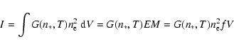
for constant volume, V, temperature T, filling factor, f, electron density,
Under the assumption of an isothermal plasma, the emission measure was obtained at the times of the lightcurve peaks for O V, Mg X, Fe XVI and Fe XIX, following Eq. (1). We have not included TRACE in the analysis of EM due to the ill-defined instrument response of the TRACE 171 Å band. The uncertainty in calculating EM using RHESSI was found to be approximately 50% using a thermal fit to the spectrum. This is in agreement with the values found by the RHESSI instrument team (McTiernan 2006).
For CDS, there are a number of factors to consider. These include uncertainties in the intensity of the line, the contribution function and the CDS calibration. While the uncertainty in measuring the line intensity is small for strong lines such as those used in our study, typically ![]() 10% (Del Zanna et al. 2001), a consideration of the contribution functions FWHM results in an uncertainty in the EM of approximately 30%. The CDS calibration is also known to be good to within 15-20% (Brekke et al. 2000). The GOES instrument is known to have limited ability for making accurate measurements of both temperature and EM. Accepted values from Garcia (2000), give the EM uncertainty to be 10%. Considering these factors, the combined photometric error for all instruments was taken to be 50%.
10% (Del Zanna et al. 2001), a consideration of the contribution functions FWHM results in an uncertainty in the EM of approximately 30%. The CDS calibration is also known to be good to within 15-20% (Brekke et al. 2000). The GOES instrument is known to have limited ability for making accurate measurements of both temperature and EM. Accepted values from Garcia (2000), give the EM uncertainty to be 10%. Considering these factors, the combined photometric error for all instruments was taken to be 50%.
![\begin{figure}
\hspace*{2mm}%
{
\includegraphics[width=8.8cm,clip = true]{0437fig4.ps} }
\end{figure}](/articles/aa/full_html/2009/06/aa10437-08/img17.gif) |
Figure 4: Panel a) shows the Mg X contribution function calculated from CHIANTI. The peak is highlighted with a dotted vertical line. This occurs at 1.25 MK. Panel b) shows the simulated temperature profile calculated by the EBTEL model (see Sect. 3 for details). The dotted horizontal line denotes the temperature of the contribution function peak from panel a), and the dashed vertical line is the time this temperature is reached. Panel c) shows the simulated density profile, and panel d) shows the simulated lightcurve for Mg X, calculated from Eq. (1). |
| Open with DEXTER | |
2.2 Velocity
The Doppler shifts at both footpoints were calculated for the duration of the flare using the five CDS emission lines, with uncertainties of ![]() 10 km s-1 (Gallagher et al. 1999; Brekke et al. 1997). The rest wavelengths for He I, O V, Mg X and Fe XVI were calculated from a region of pre-flare quiet Sun. For the Fe XIX line, a detailed analysis of the behaviour of wavelength as a function of time was conducted to establish the rest wavelength. Centroid wavelengths from both before the SXR rise and from late in the flare were averaged and corrected for both heliocentric angle and an average inclination
of 44
10 km s-1 (Gallagher et al. 1999; Brekke et al. 1997). The rest wavelengths for He I, O V, Mg X and Fe XVI were calculated from a region of pre-flare quiet Sun. For the Fe XIX line, a detailed analysis of the behaviour of wavelength as a function of time was conducted to establish the rest wavelength. Centroid wavelengths from both before the SXR rise and from late in the flare were averaged and corrected for both heliocentric angle and an average inclination
of 44![]() to obtain the rest wavelength. Figure 5 shows the Fe XIX line profiles for the right footpoint during the impulsive (a) and decay (b) phases.
to obtain the rest wavelength. Figure 5 shows the Fe XIX line profiles for the right footpoint during the impulsive (a) and decay (b) phases.
![\begin{figure}
\par\includegraphics[width=8cm,trim =20 350 5 0, clip = true]{043...
...udegraphics[width=8cm,trim =20 350 5 0, clip = true]{0437fig5b.ps}
\end{figure}](/articles/aa/full_html/2009/06/aa10437-08/img20.gif) |
Figure 5:
The line profiles of the Fe XIX emission line for the right footpoint during the impulsive phase a) and the decay phase b). Note the increasing intensity of the Fe XII blend at |
| Open with DEXTER | |
Table 2: Input parameters used for EBTEL simulation. The parameters were constrained by data when possible and the ranges of parameters investigated are shown.
3 Modelling
3.1 The Cargill model
Following Antiochos & Sturrock (1976), Cargill (1993,1994) presented a model that considered a flare that is cooling purely by conduction for a time
![]() ,
followed by purely radiative cooling for a time
,
followed by purely radiative cooling for a time
![]() .
The cooling time-scales were given by:
.
The cooling time-scales were given by:
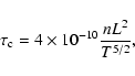
and

where
The time and temperature at which the cooling mechanism dominance changes, ![]() and T* respectively, can be calculated as follows:
and T* respectively, can be calculated as follows:
![\begin{displaymath}\tau_{*} = \tau_{\rm c_{0}} \left[ \left( \frac{\tau_{\rm r_{0}}} {\tau_{\rm c_{0}}} \right)^{7/12} - 1 \right],
\end{displaymath}](/articles/aa/full_html/2009/06/aa10437-08/img36.gif) |
(4) |
and

where
3.2 The EBTEL model
Enthalpy based thermal evolution of loops (EBTEL) model is a 0-D model that simulates the evolution of the average temperature, density, and pressure along a single strand (Klimchuk et al. 2008), calculating a single value of each of these quantities at any given time. This is a reasonable representation since temperature, density, and pressure are approximately uniform along the magnetic field, with the exception of the steep gradients in the transition region at the base of the loop.
As its name implies, EBTEL takes explicit account of the important role of enthalpy in the energetics of evolving loops. Under static equilibrium conditions, less than half of the energy deposited in the corona is radiated directly. The rest is thermally conducted down to the transition region, where it is radiated away. Under evolving conditions, chromospheric evaporation occurs when the transition region cannot accommodate the downward flux, or, if the flux is insufficient to power the transition region radiative losses, condensation occurs.
EBTEL equates an enthalpy flux with the excess or deficit heat flux. Kinetic energy is ignored because the flows are generally subsonic, except perhaps in the earliest times of an impulsive event. Another assumption made is that the radiative losses from the transition region and corona maintain a fixed proportion at all times. EBTEL has been compared with sophisticated 1-D hydrodynamic models and found to give similar results, despite using 4 orders of magnitude less computing time.
EBTEL allows for any temporal profiles of both direct plasma heating and non-thermal particle acceleration. The effects of the non-thermal electron beam are treated in a highly simplified manner. It is assumed that all of the energy goes into evaporating plasma. This is reasonable for gentle evaporation (Fisher et al. 1985), but for explosive evaporation, some of the beam energy will go into a plug of downflowing and radiating plasma deep in the chromosphere. Thus the actual energy of the beam, as inferred from RHESSI observations for example, is greater than the beam energy used in the EBTEL simulation. For a complete description of this model, refer to Klimchuk et al. (2008).
The flare loop is almost certainly composed of many strands that are heated at different times. However, the observations suggest that most of the strands are heated in approximately the same way and at approximately the same time (i.e. during the HXR burst), so the flare was modelled as a single monolithic loop. Nonetheless, some strands are expected to be heated both before and after this main bundle (e.g., Klimchuk et al. 2006), and this will result in some deviations between the model and observations.
![\begin{figure}
\par {
\includegraphics[width=16cm, trim =0 0 0 0, clip = true]{0437fig6.ps} }
\end{figure}](/articles/aa/full_html/2009/06/aa10437-08/img39.gif) |
Figure 6: The EBTEL temperature evolution (solid line) that best reproduced the observations of Sect. 2.1 is shown in the first panel, along with the heating function whose parameters are described in Table 2 (dashed line, arbitrarily scaled to show position and width). The second panel shows the corresponding model and observed emission measure evolution, with the data points corresponding in time to those in the first panel. The third panel shows the conductive and radiative losses throughout the flare on solid and dashed lines respectively. The fourth panel shows the GOES 1-8 Å lightcurve. The bottom panel shows the velocities of the right footpoint for the five CDS lines and that of the left footpoint in He I and Fe XIX. The velocities were very similar at both footpoints in all other lines and so were omitted for clarity. The EBTEL simulated velocity for Mg X is represented by the thick black line. The dotted vertical lines correspond to the flare phases (A)-(D) explained in Sect. 4.2. |
| Open with DEXTER | |
The pre-flare conditions included a temperature of 0.3 MK, an initial density of
![]() cm-3 and an emission measure of
cm-3 and an emission measure of
![]() cm-3. Input values were, where possible, constrained by observations. The loop length was determined from magnetic field extrapolations of the region (P. A. Conlon, private communication). Since it was assumed that the heating function is associated with the HXR burst, the majority of which was not observed, the shape of the heating function was inferred from previous observations of HXR bursts and the slow rise of the GOES SXR lightcurve. Thus, the most appropriate heating function was deemed to be Gaussian in shape. The amplitude of the non-thermal electron flux was constrained by the lower limit calculated from RHESSI observations and the width was inferred from the derivative of the SXR flux (Neupert 1968; Dennis & Zarro 1993). While the direct heating rate was not constrained by observations, it was assumed to have the same width as the non-thermal heating flux and to occur at the same time. Due to the sensitivity of the model parameters to cooling timescales, the cooler data points (e.g. Fe XVI, Mg X, TRACE and O V) were critical in constraining the parameters. The ranges of acceptable parameter values are shown in Table 2. The values obtained from observations are shown, along with the parameter values used in producing the results in Sect. 4. The range of parameter values shown correspond to the maximum and minimum values that produce an acceptable fit to data. The ratio of the heating components (i.e. direct to non-thermal) is also shown for the best fit parameters presented in Sect. 4, where the equivalent direct energy flux is given by the volumetric heating rate divided by the half loop length.
cm-3. Input values were, where possible, constrained by observations. The loop length was determined from magnetic field extrapolations of the region (P. A. Conlon, private communication). Since it was assumed that the heating function is associated with the HXR burst, the majority of which was not observed, the shape of the heating function was inferred from previous observations of HXR bursts and the slow rise of the GOES SXR lightcurve. Thus, the most appropriate heating function was deemed to be Gaussian in shape. The amplitude of the non-thermal electron flux was constrained by the lower limit calculated from RHESSI observations and the width was inferred from the derivative of the SXR flux (Neupert 1968; Dennis & Zarro 1993). While the direct heating rate was not constrained by observations, it was assumed to have the same width as the non-thermal heating flux and to occur at the same time. Due to the sensitivity of the model parameters to cooling timescales, the cooler data points (e.g. Fe XVI, Mg X, TRACE and O V) were critical in constraining the parameters. The ranges of acceptable parameter values are shown in Table 2. The values obtained from observations are shown, along with the parameter values used in producing the results in Sect. 4. The range of parameter values shown correspond to the maximum and minimum values that produce an acceptable fit to data. The ratio of the heating components (i.e. direct to non-thermal) is also shown for the best fit parameters presented in Sect. 4, where the equivalent direct energy flux is given by the volumetric heating rate divided by the half loop length.
4 Results
Combining the observations from the different instruments used for this study, and the results from EBTEL, the heating and cooling phases of this flare can be comprehensively described. These results are presented in Figs. 6 and 7. These figures show the evolution of the flare through the dependence of temperature, emission measure, energy losses and velocity, as discussed in Sects. 2.1 and 2.2.
![\begin{figure}
{
\includegraphics[width=9cm, trim =5 350 0 0, clip = true]{0437fig7.ps} }
\end{figure}](/articles/aa/full_html/2009/06/aa10437-08/img42.gif) |
Figure 7: This shows the dependence of emission measure on temperature for both model and data. The different phases of a solar flare are marked (A)-(D). Over-plotted are the emission measure data-points calculated in Sect. 2.1 as a function of their temperature. |
| Open with DEXTER | |
4.1 Comparison of model to data
The top two panels of Fig. 6 describe the evolution of the flare temperature and emission measure. The data points for each instrument were obtained using the analysis described in Sect. 2.1. The input parameters for EBTEL were approximated by observations and allowed to vary slightly until a good correlation with the cooling phase data was obtained. The conductive and radiative loss curves generated by EBTEL for the flare are shown in the third panel of Fig. 6. Consistent with previous observations, conduction was found to dominate initially, with radiation becoming prevalent for the remainder of the decay phase. Both the Cargill and EBTEL simulations found conduction to dominate for the first 200-400 s of the decay phase, with radiation dominating for the remaining ![]() 4000 s, referring to
4000 s, referring to
![]() and
and
![]() respectively. The time
respectively. The time ![]() at which
at which
![]() (i.e. the dominant loss mechanism switches from conduction to radiation) is
(i.e. the dominant loss mechanism switches from conduction to radiation) is ![]() 15:24 UT in both cases. However, the temperature,
15:24 UT in both cases. However, the temperature,
![]() ,
at which this occurs was found to be
,
at which this occurs was found to be ![]() 12 MK and
12 MK and ![]() 8 MK according to Cargill and EBTEL respectively. This discrepancy is due to the different approach to the modelling of the early decay phase. EBTEL simultaneously calculates the conductive and radiative losses throughout a flare while Cargill assumes cooling exclusively by either conduction or radiation at any one time. The fourth panel of this figure shows the GOES 1-8 Å lightcurve for context. The last panel shows the velocities at the loop footpoints, calculated following the analysis in
Sect. 2.2. The flow velocity at both left and right footpoints are shown for the coolest and hottest lines - He I and Fe XIX respectively, while for clarity, only the right footpoints for the remaining three lines are shown. The MgX Doppler shift simulated by EBTEL is represented by the thick black line. The simulations are in reasonable agreement with the observations. Upflows are of course predicted during the evaporation phase and downflows are predicted during the draining phase. However, the magnitudes are generally larger than those observed for reasons that we do not fully understand. Uncertainties in the velocity zero point adopted for the observations may account for the downflow discrepancy.
8 MK according to Cargill and EBTEL respectively. This discrepancy is due to the different approach to the modelling of the early decay phase. EBTEL simultaneously calculates the conductive and radiative losses throughout a flare while Cargill assumes cooling exclusively by either conduction or radiation at any one time. The fourth panel of this figure shows the GOES 1-8 Å lightcurve for context. The last panel shows the velocities at the loop footpoints, calculated following the analysis in
Sect. 2.2. The flow velocity at both left and right footpoints are shown for the coolest and hottest lines - He I and Fe XIX respectively, while for clarity, only the right footpoints for the remaining three lines are shown. The MgX Doppler shift simulated by EBTEL is represented by the thick black line. The simulations are in reasonable agreement with the observations. Upflows are of course predicted during the evaporation phase and downflows are predicted during the draining phase. However, the magnitudes are generally larger than those observed for reasons that we do not fully understand. Uncertainties in the velocity zero point adopted for the observations may account for the downflow discrepancy.
The redshifts observed in the cooler lines during phase B, if real, are likely to be an indication of a downflowing chromospheric plug that accompanies explosive evaporation. The blueshifts seen in the hotter lines around 15:30 UT suggest that some loop strands were impulsively heated after the primary flare energy release. These blueshifts are expected to be smaller than the actual upflows because the spatially unresolved line profile represents a mixture of upflowing and downflowing strands (Patsourakos & Klimchuk 2006). The small peaks seen at later times in the simulation velocity curve are a result of the piecewise continuous form used for the radiative loss function.
Figure 7 shows the evolution of the flare through the interdependence of emission measure on temperature. The data points obtained during the analysis described in Sect. 2.1 were computed at the same instant in time for any one emission line or bandpass. This figure shows the heating of the plasma (A) followed by evaporation of hot plasma (B), cooling (C) and draining (D). The plasma initially cooled to a temperature below the pre-flare value and asymptotically returned to the equilibrium state due to the low level, constant background heating.
4.2 Flare phases
Figures 6 and 7 have sections labelled (A)-(D) which refer to the different phases of the flare, from pre-flare heating to the late decay phase and are described in detail in this section.
- A)
- 14:45-15:10; Pre-flare phase: for the majority of this phase, the EBTEL parameters remained at quiet Sun values, as Fig. 6 shows. At 15:07 UT the EBTEL temperature and emission measure began to rise.
Figure 7 shows the steep temperature gradient and the initial gradual rise in emission measure. However, as the fourth panel in
Fig. 6 shows, the GOES soft X-rays began to rise slowly before this. At
 15:00 UT, a small amount of Fe XIX emission was seen in the loop
(Fig. 1) and velocities of 90 km s-1 observed in Fe XIX can be seen in the bottom panel of Fig. 6 while all of the cooler lines remain at rest. This is evidence that pre-flare heating is driving gentle chromospheric evaporation in a small number of strands heated before the HXR burst.
15:00 UT, a small amount of Fe XIX emission was seen in the loop
(Fig. 1) and velocities of 90 km s-1 observed in Fe XIX can be seen in the bottom panel of Fig. 6 while all of the cooler lines remain at rest. This is evidence that pre-flare heating is driving gentle chromospheric evaporation in a small number of strands heated before the HXR burst.
- B)
- 15:10-15:17; Impulsive phase: during the impulsive phase of a flare, the standard model predicts the propagation of non-thermal electrons to the chromosphere where they heat the ambient plasma, causing it to rise and fill the loop (Kopp & Pneuman 1976). Upflows of 80 km s-1 in Fe XIX and simultaneous cool, downflows of 20 km s-1 in He I and O V were observed and shown in the bottom panel of Fig. 6. A non-thermal electron flux of
 erg cm-2 s-1 was determined between 15:16:30 and 15:17:30 UT. This is slightly lower than the
 erg cm-2 s-1 required to drive explosive chromospheric evaporation (Fisher et al. 1985; Milligan et al. 2006a). As such, this value is taken to be a lower limit and that the maximum value of non-thermal flux occurred before 15:16 UT.
- C)
- 15:17-15:24; Soft X-ray peak: The top panel of Fig. 6 shows the temperature has peaked and begun to fall and that the emission measure and SXRs were at a maximum in this phase. As the third panel of Fig. 6 shows, during this phase, conduction was efficiently removing heat from the corona and transferring it to the chromosphere, driving slow upflows of hot emission (Zarro & Lemen 1988). These flows of 20 km s-1 in Fe XIX respectively can be seen in the bottom panel of Fig. 6.
- D)
- 15:25-16:30; Decay phase: this phase is dominated by radiative cooling, as seen in the third panel of Fig. 6. Velocities in Fe XIX were returning to quiet Sun values. The modest blueshift observed at 15:32 UT in Fe XIX suggests that the line profile contains components from evaporating strands that were heated after the main loop bundle. Between approximately
15:45 and 16:20 UT Mg X, O V and He I showed downflows of up to 40 km s-1. This implies loop draining was occurring (Brosius 2003). By the end of the simulation, all of the parameters had returned to quiet Sun values.
5 Conclusions and discussion
This paper compares a flare observed with CDS, TRACE, GOES and RHESSI to the 0-D hydrodynamic model EBTEL. Early in the impulsive phase of the flare, evidence of 8 MK emission andBy tracking the behaviour of this flare as it cooled through the response functions of the many instruments and emission lines, the evolution of the temperature and emission measure could be assessed. This evolution was then recreated using the EBTEL model, providing precise details, such as the cooling timescales and mechanisms, that cannot be easily obtained from data. For this particular flare, since the HXR burst was not fully observed, the details of the heating function could also be estimated from simulations. The description of the flare using both data and model allows for a much greater understanding of flare dynamics. The behaviour of these explosive events remains somewhat ambiguous, however further studies of this nature will help to improve the understanding of them.
The ratio of the heating functions were investigated. It was found that the observations were best reproduced when the plasma was heated approximately equally by direct and non-thermal mechanisms. This implies that both of these processes are vital during the flaring process and that flares may not be energised primarily by non-thermal particles, as previously believed (Brown 1971). This is in agreement with recent results found by Milligan (2008). There it was shown that a non-thermal electron beam is not necessarily required to obtain the high-temperature, high-density material we see in flares. However, it should be noted that the EBTEL value of the flux of non-thermal electrons required for equal heating is below the critical value for explosive evaporation hypothesised by Fisher et al. (1985). This can be explained by the over-simplified treatment of non-thermal particles by EBTEL. This requires caution for a flare of this nature, where it is evident that non-thermal particles play an important role. The model assumes that all non-thermal energy is used for evaporating plasma upward into the loop. However, this may not be entirely true. It is well known that a very small fraction of this energy is used to produce bremsstrahlung radiation (![]() 1 part in 105). It may also be possible that a more significant amount is used to force plasma down into the chromosphere and to power chromospheric emission (Allred et al. 2005; Woods et al. 2004). However, despite the approximations made by EBTEL, such as the homogenous nature of the loop or the disregard for the location of energy deposition, the temperature and emission measure curves reproduce observations very well. It is computationally efficient, running a complete simulation in a matter of seconds.
1 part in 105). It may also be possible that a more significant amount is used to force plasma down into the chromosphere and to power chromospheric emission (Allred et al. 2005; Woods et al. 2004). However, despite the approximations made by EBTEL, such as the homogenous nature of the loop or the disregard for the location of energy deposition, the temperature and emission measure curves reproduce observations very well. It is computationally efficient, running a complete simulation in a matter of seconds.
This paper has established a method that will be applied to the analysis of future events. For this case, the data was manually compared to theoretical model. However, the fitting of the parameters together with model comparison techniques is currently being investigated using a Bayesian technique for simulating values from the posterior distributions of the parameters (Adamakis et al. 2008). The purpose of this analysis is to statistically optimise the model parameters within boundaries set by observations. This approach will be used when comparing theoretical models to future data sets. The authors intend to carry out an investigation of flare hydrodynamics using the improved cadence and extensive spectral range of the Extreme Ultraviolet Imaging Spectrometer (EIS) on board Hinode. Combining these data with RHESSI spectral fits will vastly improve observations and allow for even more accurate modelling.
Acknowledgements
C.L.R. is supported by an ESA/Prodex grant administered by Enterprise Ireland. R.O.M. would like to thank the NASA Postdoctoral Program for the Fellowship award to conduct research at the NASA Goddard Space Flight Center. The work of J.A.K. is also supported by NASA. We would like to thank Brian Dennis, Dominic Zarro and the RHESSI team at NASA Goddard Space Flight Center for their advice and continued support. We would also like to thank the referee for their constructive advice in improving the overall quality of this paper.
References
- Adamakis, S., Morton-Jones, A. J., & Walsh, R. W. 2008 [arXiv:0807.4209] (In the text)
- Allred, J. C., Hawley, S. L., Abbett, W. P., & Carlsson, M. 2005, ApJ, 630, 573 [NASA ADS] [CrossRef]
- Antiochos, S. K. 1978, ApJ, 220, 1137 [NASA ADS] [CrossRef] (In the text)
- Antiochos, S. K., & Sturrock, P. A. 1976, Sol. Phys., 49, 359 [NASA ADS] [CrossRef] (In the text)
- Aschwanden, M. J., & Alexander, D. 2001, Sol. Phys., 204, 91 [NASA ADS] [CrossRef] (In the text)
- Betta, R., Peres, G., Reale, F., & Serio, S. 1997, A&AS, 122, 585 [CrossRef] [EDP Sciences]
- Bradshaw, S. J., & Cargill, P. J. 2005, A&A, 437, 311 [NASA ADS] [CrossRef] [EDP Sciences] (In the text)
- Brekke, P., Kjeldseth-Moe, O., & Harrison, R. A. 1997, Sol. Phys., 175, 511 [NASA ADS] [CrossRef]
- Brekke, P., Thompson, W. T., Woods, T. N., & Eparvier, F. G. 2000, ApJ, 536, 959 [NASA ADS] [CrossRef] (In the text)
- Brosius, J. W. 2003, ApJ, 586, 1417 [NASA ADS] [CrossRef] (In the text)
- Brown, J. C. 1971, Sol. Phys., 18, 489 [NASA ADS] [CrossRef] (In the text)
- Cargill, P. J. 1993, Sol. Phys., 147, 263 [NASA ADS] [CrossRef] (In the text)
- Cargill, P. J. 1994, ApJ, 422, 381 [NASA ADS] [CrossRef]
- Cargill, P. J., Mariska, J. T., & Antiochos, S. K. 1995, ApJ, 439, 1034 [NASA ADS] [CrossRef] (In the text)
- Culhane, J. L., Vesecky, J. F., & Phillips, K. J. H. 1970, Sol. Phys., 15, 394 [NASA ADS] [CrossRef] (In the text)
- Culhane, J. L., Phillips, A. T., Inda-Koide, M., et al. 1994, Sol. Phys., 153, 307 [NASA ADS] [CrossRef] (In the text)
- Del Zanna, G., & Mason, H. E. 2005, A&AS, 433, 731 [NASA ADS] (In the text)
- Del Zanna, G., Bromage, B. J. I., Landi, E., & Landini, M. 2001, A&A, 379, 708 [NASA ADS] [CrossRef] [EDP Sciences] (In the text)
- Dennis, B. R., & Schwartz, R. A. 1989, Sol. Phys., 121, 75 [NASA ADS]
- Dennis, B. R., & Zarro, D. M. 1993, Sol. Phys., 146, 177 [NASA ADS] [CrossRef]
- Dere, K. P., Landi, E., Mason, H. E., Monsignori Fossi, B. C., & Young, P. R. 1997, A&AS, 125, 149 [CrossRef] [EDP Sciences]
- Donnelly, R. F., Grubb, R. N., & Cowley, F. C. 1977, NASA STI/Recon Technical Report N, 78, 13992
- Doschek, G. A., & Warren, H. P. 2005, ApJ, 629, 1150 [NASA ADS] [CrossRef] (In the text)
- Doschek, G. A., Cheng, C. C., Oran, E. S., Boris, J. P., & Mariska, J. T. 1983, ApJ, 265, 1103 [NASA ADS] [CrossRef] (In the text)
- Fisher, G. H., Canfield, R. C., & McClymont, A. N. 1985, ApJ, 289, 414 [NASA ADS] [CrossRef]
- Gallagher, P. T., Phillips, K. J. H., Harra-Murnion, L. K., Baudin, F., & Keenan, F. P. 1999, A&A, 348, 251
- Garcia, H. A. 2000, ApJS, 127, 189 [NASA ADS] [CrossRef] (In the text)
- Handy, B. N., Acton, L. W., Kankelborg, C. C., et al. 1999, Sol. Phys., 187, 229 [NASA ADS] [CrossRef] (In the text)
- Harrison, R. A., Sawyer, E. C., Carter, M. K., et al. 1995, Sol. Phys., 162, 233 [NASA ADS] [CrossRef] (In the text)
- Klimchuk, J. A. 2006, Sol. Phys., 234, 41 [NASA ADS] [CrossRef] (In the text)
- Klimchuk, J. A., & Cargill, P. J. 2001, ApJ, 553, 440 [NASA ADS] [CrossRef] (In the text)
- Klimchuk, J. A., López Fuentes, M. C., & Devore, C. R. 2006, Heating of the Magnetically Closed Corona, in Proceedings of SOHO-17: Ten Years of SOHO and Beyond, (ESA SP-617), ed. H. Lacoste (Noordwijk: ESA) (In the text)
- Klimchuk, J. A., Patsourakos, S., & Cargill, P. J. 2008, ApJ, 682, 1351 [NASA ADS] [CrossRef] (In the text)
- Kopp, R. A., & Pneuman, G. W. 1976, Sol. Phys., 50, 85 [NASA ADS] (In the text)
- Landi, E., & Phillips, K. J. H. 2006, ApJS, 166, 421 [NASA ADS] [CrossRef]
- Lin, R. P., Dennis, B. R., & Benz, A. O. 2002, Sol. Phys., 210, 3 [NASA ADS] [CrossRef] (In the text)
- McTiernan, J. 2006, BAAS, 38, 215 [NASA ADS] (In the text)
- Milligan, R. O. 2008, ApJ, 680, L157 [NASA ADS] [CrossRef] (In the text)
- Milligan, R. O., Gallagher, P. T., Mathioudakis, M., et al. 2006a, ApJ, 638, L117 [NASA ADS] [CrossRef]
- Milligan, R. O., Gallagher, P. T., Mathioudakis, M., & Keenan, F. P. 2006b, ApJ, 642, L169 [NASA ADS] [CrossRef]
- Neupert, W. M. 1968, ApJ, 153, L59 [NASA ADS] [CrossRef]
- Patsourakos, S., & Klimchuk, J. A. 2006, ApJ, 647, 1452 [NASA ADS] [CrossRef] (In the text)
- Peres, G., Serio, S., Vaiana, G. S., & Rosner, R. 1982, ApJ, 252, 791 [NASA ADS] [CrossRef]
- Reale, F. 2007, A&A, 471, 271 [NASA ADS] [CrossRef] [EDP Sciences] (In the text)
- Reeves, K. K., & Warren, H. P. 2002, ApJ, 578, 590 [NASA ADS] [CrossRef] (In the text)
- Rosner, R., Tucker, W. H., & Vaiana, G. S. 1978, ApJ, 220, 643 [NASA ADS] [CrossRef] (In the text)
- Saint-Hilaire, P., & Benz, A. O. 2002, Sol. Phys., 210, 287 [NASA ADS] [CrossRef] (In the text)
- Sarkar, A., & Walsh, R. W. 2008, ApJ, 683, 516 [NASA ADS] [CrossRef] (In the text)
- Teriaca, L., Falchi, A., Falciani, R., Cauzzi, G., & Maltagliati, L. 2006, A&A, 455, 1123 [NASA ADS] [CrossRef] [EDP Sciences] (In the text)
- Vrsnak, B., Temmer, M., Veronig, A., Karlický, M., & Lin, J. 2006, Sol. Phys., 234, 273 [NASA ADS] [CrossRef] (In the text)
- Warren, H. P., & Winebarger, A. R. 2007, ApJ, 666, 1245 [NASA ADS] [CrossRef] (In the text)
- White, S. M., Thomas, R. J., & Schwartz, R. A. 2005, Sol. Phys., 227, 231 [NASA ADS] [CrossRef] (In the text)
- Woods, T. N., et al. 2004, Geophys. Res. Lett., 31, 10802 [NASA ADS] [CrossRef]
- Zarro, D. M., & Lemen, J. R. 1988, ApJ, 329, 456 [NASA ADS] [CrossRef] (In the text)
Footnotes
- ...n
![[*]](/icons/foot_motif.gif)
- A study of the contribution function dependence on density was carried out. It was found that varying n* by two orders of magnitude resulted in little or no change to the contribution function. This density was assigned a constant value of 1011 cm-3.
All Tables
Table 1: Rest wavelengths and temperature of emission lines and bandpasses used in this study.
Table 2: Input parameters used for EBTEL simulation. The parameters were constrained by data when possible and the ranges of parameters investigated are shown.
All Figures
| |
Figure 1: Evolution of the GOES C3.0 flare observed on 2002 March 26 between 15:00 UT and 16:30 UT. RHESSI 6-12 and 12-25 keV images, integrated over two minutes are shown in the top two panels. The contours from O V and Fe XIX observed at 15:09 UTare overplotted in red and yellow respectively. Fe XIX (8 MK), Fe XVI (2.5 MK), TRACE/171 Å (1.0 MK) and O V (0.25 MK) emission is shown in the next four panels. The dotted box overplotted on the Fe XIX images represents the region of the loop used in the temperature and emission measure investigation. The bottom panel shows the GOES 1-8 Å, RHESSI 3-6, 6-12 and 12-25 keV lightcurves. RHESSI was in eclipse until 15:15 UT and passed through the South Atlantic Anomaly between 15:35 UT and 15:58 UT. The vertical dotted lines (and corresponding arrows) on the GOES plot represent the start and end times of the CDS rasters above. |
| Open with DEXTER | |
| In the text | |
| |
Figure 2: The top panel shows the RHESSI photon spectrum between 15:16:30 UT and 15:17:30 UT. The residuals are shown in the bottom panel. |
| Open with DEXTER | |
| In the text | |
| |
Figure 3: Linear plot of the lightcurves of emission observed by GOES, CDS and TRACE. The data points were fit using a spline interpolation. The verticals represent the peaks of the lightcurve fits. |
| Open with DEXTER | |
| In the text | |
| |
Figure 4: Panel a) shows the Mg X contribution function calculated from CHIANTI. The peak is highlighted with a dotted vertical line. This occurs at 1.25 MK. Panel b) shows the simulated temperature profile calculated by the EBTEL model (see Sect. 3 for details). The dotted horizontal line denotes the temperature of the contribution function peak from panel a), and the dashed vertical line is the time this temperature is reached. Panel c) shows the simulated density profile, and panel d) shows the simulated lightcurve for Mg X, calculated from Eq. (1). |
| Open with DEXTER | |
| In the text | |
| |
Figure 5:
The line profiles of the Fe XIX emission line for the right footpoint during the impulsive phase a) and the decay phase b). Note the increasing intensity of the Fe XII blend at |
| Open with DEXTER | |
| In the text | |
| |
Figure 6: The EBTEL temperature evolution (solid line) that best reproduced the observations of Sect. 2.1 is shown in the first panel, along with the heating function whose parameters are described in Table 2 (dashed line, arbitrarily scaled to show position and width). The second panel shows the corresponding model and observed emission measure evolution, with the data points corresponding in time to those in the first panel. The third panel shows the conductive and radiative losses throughout the flare on solid and dashed lines respectively. The fourth panel shows the GOES 1-8 Å lightcurve. The bottom panel shows the velocities of the right footpoint for the five CDS lines and that of the left footpoint in He I and Fe XIX. The velocities were very similar at both footpoints in all other lines and so were omitted for clarity. The EBTEL simulated velocity for Mg X is represented by the thick black line. The dotted vertical lines correspond to the flare phases (A)-(D) explained in Sect. 4.2. |
| Open with DEXTER | |
| In the text | |
| |
Figure 7: This shows the dependence of emission measure on temperature for both model and data. The different phases of a solar flare are marked (A)-(D). Over-plotted are the emission measure data-points calculated in Sect. 2.1 as a function of their temperature. |
| Open with DEXTER | |
| In the text | |
Copyright ESO 2009
Current usage metrics show cumulative count of Article Views (full-text article views including HTML views, PDF and ePub downloads, according to the available data) and Abstracts Views on Vision4Press platform.
Data correspond to usage on the plateform after 2015. The current usage metrics is available 48-96 hours after online publication and is updated daily on week days.
Initial download of the metrics may take a while.