Fig. 1
Download original image
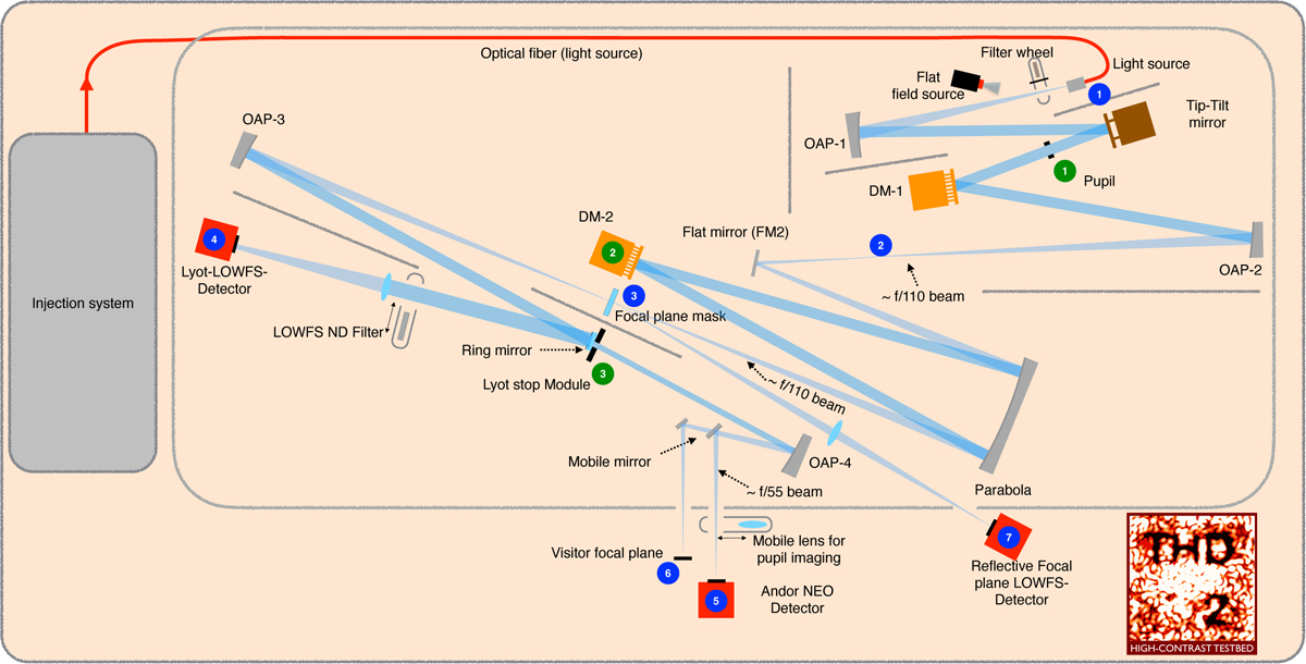
THD2 testbed layout. The blue circles indicate the focal planes and the green circles indicate the pupil planes. The laser injection system positioned on the left side injects the light through a fiber into the top right part of the testbed in this figure (blue circle 1). The available monochromatic laser diodes emit at wavelengths 638 nm, 705 nm, and 783 nm, separately or combined. A filter wheel containing one clear position for normal imaging, a light trap for dark images, and a flat mirror for injection of a flat-field source is located right after the fiber. A tip-tilt mirror is located before the first pupil plane that contains the aperture mask (green circle 1). The beam then hits DM1, which is the out-of-pupil DM on THD2, and converges through an unused focal plane (blue circle 2) to reach the in-pupil DM2 (green circle 2). The following focal plane contains the FPM (blue circle 3) and then leads to the LS mount (green circle 3). A ring mirror around the LS reflects the light toward a LOWFS camera (blue circle 4), not used for the work in this paper. The reflection off of the HLC’s central dot is imaged onto a second LOWFS camera (blue circle 7), used for closed-loop TT control in this paper. The transmitted light is focused on the science camera (blue circle 5) or alternatively directed to a secondary detector plane (blue circle 6) by means of an insertable flat mirror. A lens can be moved into the beam before the science camera to obtain pupil images, and a linear polarizer is located before this camera as well.
Current usage metrics show cumulative count of Article Views (full-text article views including HTML views, PDF and ePub downloads, according to the available data) and Abstracts Views on Vision4Press platform.
Data correspond to usage on the plateform after 2015. The current usage metrics is available 48-96 hours after online publication and is updated daily on week days.
Initial download of the metrics may take a while.