Fig. 1.
Download original image
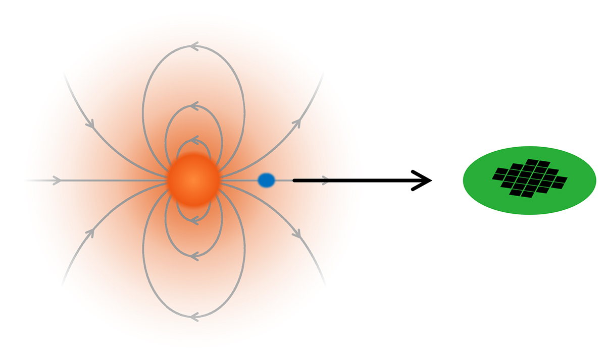
Diagram illustrating the geometry we assume in the free-free absorption modelling. The magnetic field dipole is shown in grey. We place the emitter above the magnetic pole and assume the emission propagates radially outwards along the line of sight, to ensure the most conservative mass-loss upper limit of all possible geometries. The emission region (shown in blue) is assumed to be as close to the observer as possible, to minimise the free-free absorption along its path (black arrow) to the detector (shown here as a representation of LOFAR).
Current usage metrics show cumulative count of Article Views (full-text article views including HTML views, PDF and ePub downloads, according to the available data) and Abstracts Views on Vision4Press platform.
Data correspond to usage on the plateform after 2015. The current usage metrics is available 48-96 hours after online publication and is updated daily on week days.
Initial download of the metrics may take a while.