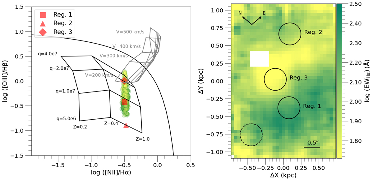
Fig. 6.
Download original image
Ionization mechanism diagnostic diagram of region ID26. Left panel: Ionization mechanism diagnostic diagram in which we plot the emission line flux ratios [OIII]/Hβ vs. NII]/Hα for all spaxels covered by the IFU/GMOS FoV. The integrated points (black symbols) correspond to the analyzed Regs. 1, 2, and 3. The spaxel points are color-coded following the EWHα map (shown in the right panel of this figure). The black and gray grids correspond to the photoionizing and shock-ionizing models, respectively. The grid vertices of photoionizing model were computed in a range of metalicities of 0.2, 0.4, and 1 Z⊙, an ionizing parameter of 5 × 10⁶, 1 × 10⁷, 2 × 10⁷, and 4 × 107 cm s−1, with an Ne of 10 cm−3, and for an instantaneous burst (Kewley et al. 2001). The grid vertices of the shock-ioionizing model were calculated in a range of shock velocities of 200, 300, 400, and 500 km s−1, a magnetic field from left to right of 0.0001, 0.5, 1.0, 2.0, 3.23, 4.0, 5.0, and 10.0 μG, with an Ne of 1 cm−3, with a metallcity of 1 Z⊙, and a composition of shock+precursor regions (Allen et al. 2008). As reference, we also display the maximum photoionization line (in black) from Kewley et al. (2001). Right panel: EWHα map. The dashed circle in the bottom right corner represents the seeing. The bar in the bottom left corner is the angular scale. The white square corresponds to a poor fiber in the IFU/GMOS.
Current usage metrics show cumulative count of Article Views (full-text article views including HTML views, PDF and ePub downloads, according to the available data) and Abstracts Views on Vision4Press platform.
Data correspond to usage on the plateform after 2015. The current usage metrics is available 48-96 hours after online publication and is updated daily on week days.
Initial download of the metrics may take a while.