Fig. 1
Download original image
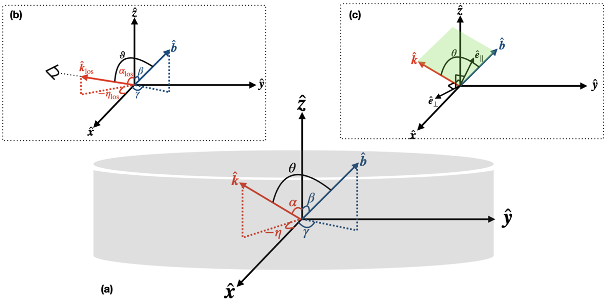
Coordinate system in the LVG geometry reference frame. LVG geometry is defined by the unit vectors, ![]() ,
, ![]() and
and ![]() . In (a), the magnetic field direction,
. In (a), the magnetic field direction, ![]() , and radiation direction,
, and radiation direction, ![]() , unit vectors are drawn, with their respective angles with respect to the LVG coordinate system. Throughout the paper, we use the symbol
, unit vectors are drawn, with their respective angles with respect to the LVG coordinate system. Throughout the paper, we use the symbol ![]() , for the projection of the magnetic field onto the radiation direction. The translucent gray cylinder indicates the typical geometry we have used in our calculations, with weaker velocity gradients (and thus a larger LVG region) in the perpendicular direction. In (b), the special case when the radiation direction coincides with the line-of-sight is drawn. The projection angle of the magnetic field onto the line-of-sight direction is indicated by ϑ. In (c), the magnetic field direction,
, for the projection of the magnetic field onto the radiation direction. The translucent gray cylinder indicates the typical geometry we have used in our calculations, with weaker velocity gradients (and thus a larger LVG region) in the perpendicular direction. In (b), the special case when the radiation direction coincides with the line-of-sight is drawn. The projection angle of the magnetic field onto the line-of-sight direction is indicated by ϑ. In (c), the magnetic field direction, ![]() , and radiation direction,
, and radiation direction, ![]() , unit vectors are drawn, along with the unit vectors ê|| and ê⊥, that define the radiation polarization directions, in, and perpendicular to, the plane (indicated in green) spanned by the magnetic field and radiation directions. In our calculations, we use an axisymmetric LVG geometry, with velocity gradient λ in the
, unit vectors are drawn, along with the unit vectors ê|| and ê⊥, that define the radiation polarization directions, in, and perpendicular to, the plane (indicated in green) spanned by the magnetic field and radiation directions. In our calculations, we use an axisymmetric LVG geometry, with velocity gradient λ in the ![]() -direction, that defines the symmetry axis, and velocity gradient λ/ϵ in the
-direction, that defines the symmetry axis, and velocity gradient λ/ϵ in the ![]() and
and ![]() directions. Unless otherwise indicated, we used β = 0 and ϑ = π/2 for the magnetic field and line-of-sight direction in our calculations.
directions. Unless otherwise indicated, we used β = 0 and ϑ = π/2 for the magnetic field and line-of-sight direction in our calculations.
Current usage metrics show cumulative count of Article Views (full-text article views including HTML views, PDF and ePub downloads, according to the available data) and Abstracts Views on Vision4Press platform.
Data correspond to usage on the plateform after 2015. The current usage metrics is available 48-96 hours after online publication and is updated daily on week days.
Initial download of the metrics may take a while.