Fig. 7.
Download original image
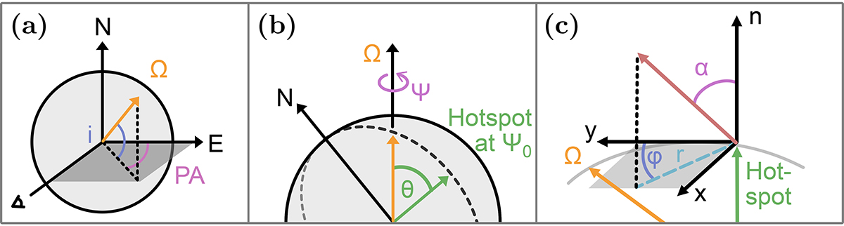
Pulsar geometry and the beam pattern of the toy model. In panel a the pulsar geometry is shown as a sketch with the spin axis (Ω) located by the inclination (i) and the position angle of the pulsar spin (PA). The position of the emission region on the surface with respect to the spin axis is determined by the magnetic co-latitude θ and the rotation phase is denoted by Ψ, shown in panel b. Panel c shows that the beam pattern is defined by the angles α and φ, where α is measured from the normal and the reference axis for φ is the y-axis, which points towards the spin axis which corresponds to north when the emission region is at Ψ0.
Current usage metrics show cumulative count of Article Views (full-text article views including HTML views, PDF and ePub downloads, according to the available data) and Abstracts Views on Vision4Press platform.
Data correspond to usage on the plateform after 2015. The current usage metrics is available 48-96 hours after online publication and is updated daily on week days.
Initial download of the metrics may take a while.