Fig. 14
Download original image
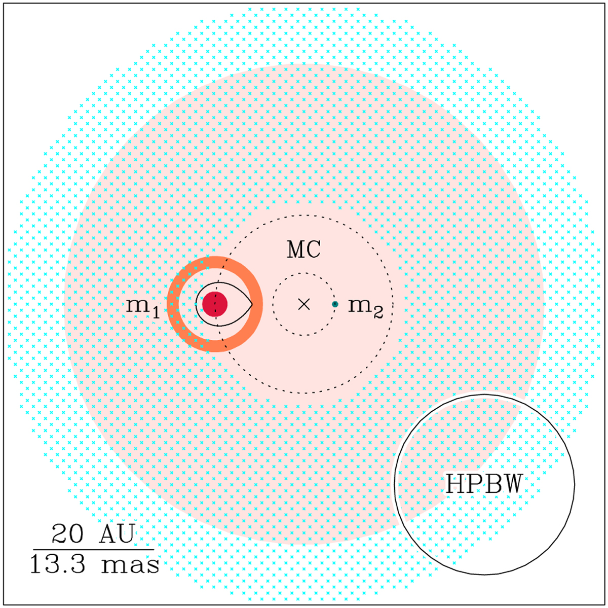
Sketch of the binary system and dust and salts components at the center of OH 231.8. In this figure, the point of view is along the orbital axis of the binary system, i.e., the orbits are in the plane of the drawing. The red crimson circle represent the primary, the Mira star QXPup (m1), showing its approximate size. The pale blue dot represents the location of the secondary (m2), but the size is not to scale. The × -symbol (MC) marks the location of the center of masses of the system. We adopted a mass ratio q = m1/m2 of 0.35. The two black dashed circumferences show the orbits of the two stars (we assumed circular orbits for simplicity). The black ovoid shape around T1 shows the extent of its Roche lobe according to Leahy & Leahy (2015), assuming synchronous rotation, namely, p = 1 in their Eq. (2). The orange ring around m1 shows the location of the SiO masers (RSiO ~ 6 AU) and the dust condensation zone (Rd ~ 7.5 AU) where hot dust is detected. The pale pink and cyan-crossed large circles show respectively the size of the (circumbinary) dust- and NaCl-disk detected. In the bottom-left corner, we include a scale in both physical (AU) and angular (mas) units for the adopted distance of 1500 pc. The size of the typical HPBW of these observations (20 mas) is also shown in the bottom-right corner.
Current usage metrics show cumulative count of Article Views (full-text article views including HTML views, PDF and ePub downloads, according to the available data) and Abstracts Views on Vision4Press platform.
Data correspond to usage on the plateform after 2015. The current usage metrics is available 48-96 hours after online publication and is updated daily on week days.
Initial download of the metrics may take a while.