Fig. 5
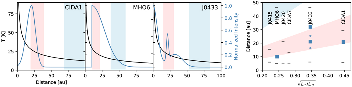
Left panels: temperature profile of the midplane is obtained from Eq. (5) and plotted with a black curve. The blue curve shows the best radial profile obtained from the continuum UV-modeling, which was normalized to the peak emission. Vertical red and light blue shaded regions show the possible locations of the CO (light red) and N2 (light blue) icelines. Right panel: disk radius is shown versus the square root of stellar luminosity (![]() ). The shaded regions show the iceline location for CO (light red) and N2 (light blue), obtained from Eq. (6). The peak location of the modeled continuum emission rings are shown in squares, while the gap locations of J0433 are shown with dots. The lower line in each target marks half of the theoretical resolution given by the longest baseline for each dataset, as measured from the center, and the upper line marks the continuum R90.
). The shaded regions show the iceline location for CO (light red) and N2 (light blue), obtained from Eq. (6). The peak location of the modeled continuum emission rings are shown in squares, while the gap locations of J0433 are shown with dots. The lower line in each target marks half of the theoretical resolution given by the longest baseline for each dataset, as measured from the center, and the upper line marks the continuum R90.
Current usage metrics show cumulative count of Article Views (full-text article views including HTML views, PDF and ePub downloads, according to the available data) and Abstracts Views on Vision4Press platform.
Data correspond to usage on the plateform after 2015. The current usage metrics is available 48-96 hours after online publication and is updated daily on week days.
Initial download of the metrics may take a while.