Fig. A.3.
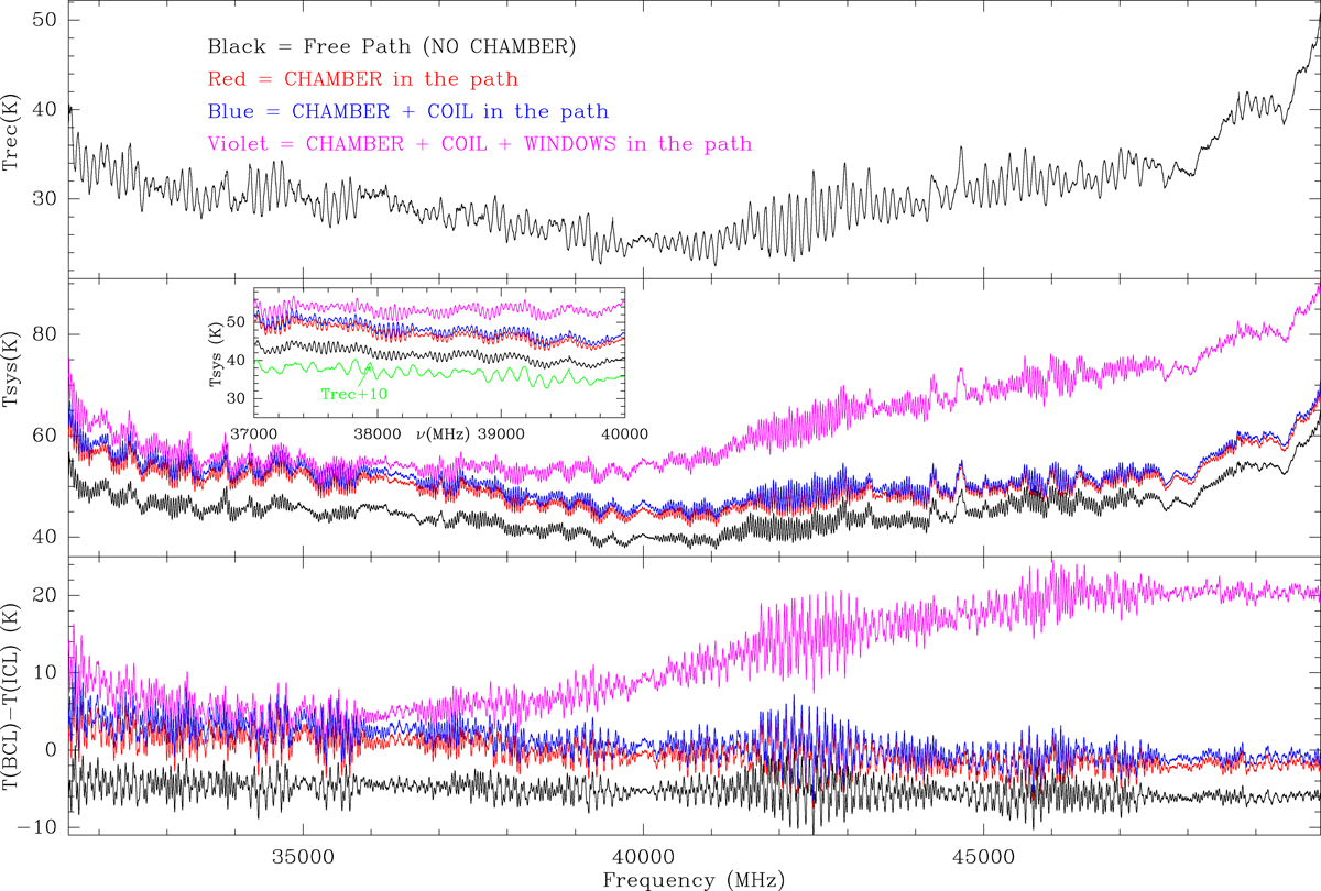
Top: receiver noise temperature in the Q band derived from two absorbers at ambient and liquid N2 temperatures. Middle: system temperature (receiver + background cold load) when different elements of the system are inserted in the beam path of the receiver: free path (black), chamber (red), chamber plus RF coil (blue), and chamber plus RF coild plus TeflonTM windows (violet). The inset shows a zoom-in on frequency with the receiver temperature (top panel; free path) shifted by 10 K in cyan. Bottom: temperature difference between background (BCL) and internal (ICL) cold loads. Colours correspond to the same conditions as those indicated in the top panel. The receiver noise, system temperature, and the cold load temperature differences are in K.
Current usage metrics show cumulative count of Article Views (full-text article views including HTML views, PDF and ePub downloads, according to the available data) and Abstracts Views on Vision4Press platform.
Data correspond to usage on the plateform after 2015. The current usage metrics is available 48-96 hours after online publication and is updated daily on week days.
Initial download of the metrics may take a while.