Fig. 7.
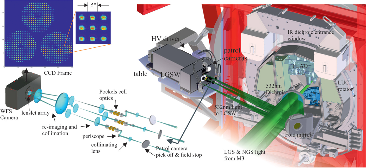
Optical path and CAD model of one of the wavefront sensors. The light from the LGSs enters from the right side in its 4 arcmin wide constellation. Patrol cameras enable a fast acquisition and position control of the guide stars. Inside the wavefront sensor units motorized mirrors stabilize the field and the pupil, driven by the signals from the WFS CCD. After that the gating units slice out the photon bunches originating from the 12 km distant scattering, letting a 300 m range (i.e. 2 μs) long part pass to the wavefront sensor detector. These Pockels cells units operate at the same 10 kHz as the laser pulses are sent to sky. The wavefront sensor detector accumulates the charge originating from 10 consecutive pulses, being read out at a 1 kHz frame rate. The wavefront sensor CCD frame of one telescope side with the three LGSs is shown on the left. Having passed a common microlens array in front of the detector, all three guide stars show a Shack–Hartmann spot pattern on the detector. From each spot the local wavefront slope can be measured, enabling the reconstruction and correction of the ground-layer turbulence. Because LGS spots are often larger than NGSs, the sub-aperture’s field of view amounts to ∼5 ′′ sampled with 8 × 8 pixels on the CCD frame.
Current usage metrics show cumulative count of Article Views (full-text article views including HTML views, PDF and ePub downloads, according to the available data) and Abstracts Views on Vision4Press platform.
Data correspond to usage on the plateform after 2015. The current usage metrics is available 48-96 hours after online publication and is updated daily on week days.
Initial download of the metrics may take a while.