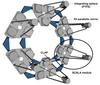
Fig. 1

Top: hexagonal arrangement of the six submodules of SCALA. This structure is mounted in front of the entrance pupil of the telescope. The lower module shows the position of the reference photodiode (CLAP). Bottom: SCALA scheme where it is possible to see the lamp system and the flip mirror that allows the selection of lamp output that illuminates the monochromator entrance, the fiber bundle that feeds the integrating sphere (IS), and the calibrated photodiode (CLAP), which faces the collimated beam reflected by the mirror. The dotted line represents the light path. The flipping mirror is placed in the housing of the halogen lamp to avoid light leaks. The two small boxes within the lamps boxes represent the place where the order sorting filters (F1 and F2) are located. In this schematic drawing, the angle between the optical axes of the IS and mirror is exaggerated and the IS output is simplified to a point source.
Current usage metrics show cumulative count of Article Views (full-text article views including HTML views, PDF and ePub downloads, according to the available data) and Abstracts Views on Vision4Press platform.
Data correspond to usage on the plateform after 2015. The current usage metrics is available 48-96 hours after online publication and is updated daily on week days.
Initial download of the metrics may take a while.