Fig. 1
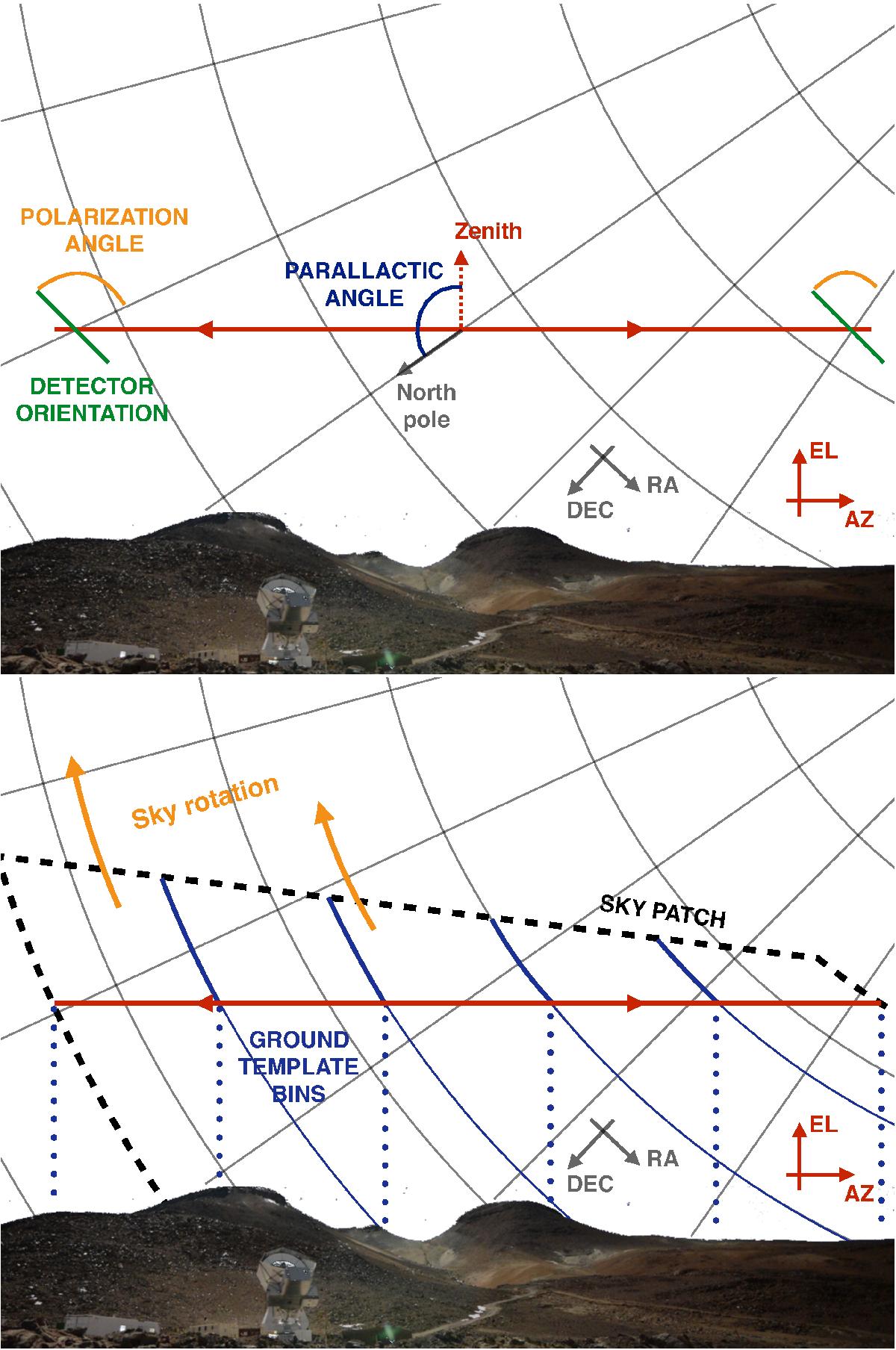
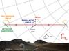
Top panel: geometry of a constant elevation observation. Grey lines represent the equatorial coordinate system at some fixed time instant. The red line shows the scan in the horizontal coordinate system with the telescope assumed to chop back and forth along a constant elevation direction. The orientation of a polarization sensitive detector is shown with green lines. It is assumed to be fixed in horizontal coordinates and thus varies somewhat with the observation’s azimuth due to changes in the parallactic angle, which is marked in blue. The bottom panel emphasizes the effects due to the sky rotation. This is marked with orange arrows. As the sky rotates, the constant elevation scan progressively covers the sky area delineated by a dashed black line. The area above the red line has been already observed. Also marked are its sub-areas, which are observed when the telescope’s azimuth falls in one of the azimuthal bins. These for instance may be used to discretize the ground-pickup and are shown here with blue dotted lines. These sub-areas remain disjoint as the sky rotates whenever the azimuthal bins are disjoint, and are separated in the figure with blue solid lines.
Current usage metrics show cumulative count of Article Views (full-text article views including HTML views, PDF and ePub downloads, according to the available data) and Abstracts Views on Vision4Press platform.
Data correspond to usage on the plateform after 2015. The current usage metrics is available 48-96 hours after online publication and is updated daily on week days.
Initial download of the metrics may take a while.