Fig. 3
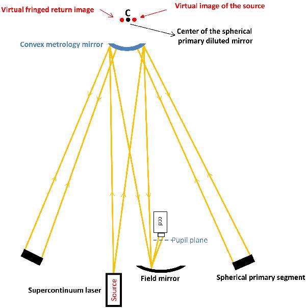
Schema describing the coherencing technique. A laser source lights up a convex mirror near the curvature center of the spherical diluted primary mirror. The convex metrology mirror creates a virtual image of this source that is seen as a point source by the primary segments. The light comes back on a field mirror where fringes are formed. A CCD is placed a few centimeters after the exit pupil plane, where the diffraction of the small subapertures is high enough to observe the fringes (the beams overlap). This optical design tolerates translation ( ± 2 mm with the OHP prototype optics) of the metrology mirror at the curvature center. With a broadband laser source, finding the white fringe allows us to adjust the piston balance within one micron. On the prototype at OHP, the laser source, the field mirror and the CCD are placed on a metrology table (Fig. 7).
Current usage metrics show cumulative count of Article Views (full-text article views including HTML views, PDF and ePub downloads, according to the available data) and Abstracts Views on Vision4Press platform.
Data correspond to usage on the plateform after 2015. The current usage metrics is available 48-96 hours after online publication and is updated daily on week days.
Initial download of the metrics may take a while.