Fig. 7
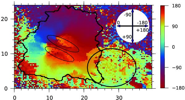
LRF azimuth map in the TIP data. The corresponding maps of other quantities are shown in the bottom panels of Figs. 2 and 4. Two thin ellipses mark the LBs. The thick ellipse shows the region where SFPs arrive. Zero degree azimuth corresponds to the ( − x) direction, and ± 180° correspond to the ( + x) direction (see arrows in the white circle). The abscissa is in arcsec.
Current usage metrics show cumulative count of Article Views (full-text article views including HTML views, PDF and ePub downloads, according to the available data) and Abstracts Views on Vision4Press platform.
Data correspond to usage on the plateform after 2015. The current usage metrics is available 48-96 hours after online publication and is updated daily on week days.
Initial download of the metrics may take a while.