Fig. 2
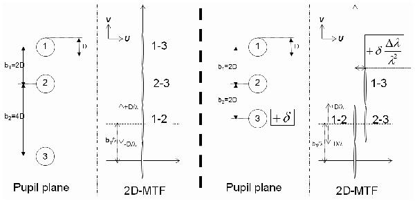
Schematic representation of a simple 3T non-redundant (left) and redundant (right) linear configuration for a dispersed fringe instrument. For each case, we show the pupil plane at the entrance of the spectrograph and the 2D Modulation Transfer Function (MTF). By adding an optical path difference (δ) on one of the pupil in the redundant case, one can separate the fringe signals in the MTF plane despite the redundancy.
Current usage metrics show cumulative count of Article Views (full-text article views including HTML views, PDF and ePub downloads, according to the available data) and Abstracts Views on Vision4Press platform.
Data correspond to usage on the plateform after 2015. The current usage metrics is available 48-96 hours after online publication and is updated daily on week days.
Initial download of the metrics may take a while.