A&A 434, 1-15 (2005)
DOI: 10.1051/0004-6361:20034194
Solutions of the axi-symmetric Poisson equation from elliptic integrals
I. Numerical splitting methods
J.-M. Huré1,2
1 - LUTh (CNRS UMR 8102), Observatoire de Paris-Meudon, Place Jules Janssen, 92195 Meudon Cedex, France
2 -
Université Paris 7 Denis Diderot, 2 place Jussieu, 75251 Paris Cedex 05, France
Received 14 August 2003 / Accepted 10 December 2004
Abstract
In a series of two papers, we present numerical, integral-based methods to compute accurately the self-gravitating field and potential induced by tri-dimensional, axially symmetric fluids, with a special regard for tori, discs and rings.
This first article is concerned with a fully numerical approach. Complex shapes, small/large aspect ratios, important density gradients and compact/extended systems can be accounted for. Loop singularities in the Poisson integrals are carefully treated from kernel splitting and/or density splitting. Field components are obtained from density splitting: the local density field is separated into a vertically homogeneous contribution for which the integrable singularity is known in a closed form, plus a "residual'' contribution which yields a regular integrand. This technique is exact in the vertically homogeneous limit. The potential is computed from double splitting: kernel splitting (to isolate explicitly the singular function), followed by density splitting. In each two directions, numerical quadratures are performed using a dynamical mesh (very efficient for flat and extended systems), combined with a high-order, irregular-spacing scheme. Global performances are demonstrated through a few test-configurations. The accuracy is potentially very high, and can reach the computer precision (for simple geometries and smooth density profiles). In terms of computing time to precision ratio, present methods are asymptotically more efficient than classical finite-difference methods. These can be employed either as a "Poisson-solver'' or only to compute a sub-set of Dirichlet/Neumann-type boundary conditions in order to initialize spectral/finite-difference/finite element methods.
As an example of an astrophysical application, we determine the structure of an uniformly rotating polytrope belonging to the compressible, Dyson-Wong sequence.
In a second paper (Paper II), we show that singularities are integrable analytically for geometrically thin systems where the density is of the form
 .
Improvements and extensions (such as the non-axi-symmetric case) are possible and discussed.
Key words: hydrodynamics - methods: numerical
1 Introduction
Reliable models and simulations of self-gravitating systems like the cosmological fluid, galaxies, stars, interstellar clouds, and tori, discs and rings![[*]](/icons/foot_motif.gif) need accurate solutions of the Poisson equation
need accurate solutions of the Poisson equation
 |
(1) |
where  is the self-induced potential and
  is the mass density. Cases where this equation has an analytical, tractable solution are rare or correspond to very simplified situations (e.g. Binney & Tremaine 1987), because astrophysical fluids have i) complex geometries/shapes; ii) very small/very large aspect ratios; iii) at least bi-dimensional density gradients; and iv) open boundaries. Numerical solutions, difficult to compute in general, are very powerful as they give a mean to investigate real systems. Methods of inversion of Eq. (1), also called "Poisson solvers'', are customarily classified into two categories (Müller & Steinmetz 1995): difference methods and integral methods. In difference methods, Eq. (1) is solved for
  on a grid, requiring boundary conditions. Dirichlet/Neumann boundary conditions are exactly known at infinity (the potential and derivatives vanish), but dealing with an infinite domain is not convenient, unless a space mapping is considered (e.g. Clément 1974). Boundary conditions can easily be computed with great accuracy just outside the source. Internal solutions found with difference methods have generally low or limited precision (even with exact boundary conditions), but algorithms are extremely fast once initialized.
One may then prefer the integral method where
  is obtained from the Poisson integral
 |
(2) |
with the advantage that the summation over the gas volume  naturally stops at the system boundaries. This approach not only produces missing Dirichlet boundary conditions (Bodo & Curir 1992; Störzer 1993; Cohl & Tohline 1999), but can be used in the entire domain. Integral methods are often rejected because of point mass singularities (i.e. when
 in Eq. (2)) which make the above integral improper everywhere inside the fluid. Often, people circumvent the difficulty by softened gravity (e.g. Adams et al. 1989). The second reason - probably the main one - is their possible prohibitive execution time
![[*]](/icons/foot_motif.gif) .
But when singularities are properly treated, potential values can be determined with high accuracy, orders of magnitudes larger than finite-difference based methods allow. With the era of fast computers and especially of parallel programming (e.g. Borges & Daripa 2001), integral methods should be more and more accessible, and it seems justified to develop efficient tools accordingly. Spectral methods - a third category - are probably the most efficient techniques (Greengard & Lee 1996; Christopher et al. 1997; Chen et al. 2000; Lai et al. 2002), at least for compact systems. This approach, possibly combined with mapping and space compactification, is commonly employed to model rotating stars (Clément 1974; Bonazzola et al. 1998), but it remains exceptional for toroidal configurations (Ansorg et al. 2003a,b). Expanded Green functions are not convenient in practice because these are alternate and infinite series which do not converge inside sources as often outlined (e.g. Clément 1974; Störzer 1993; Cohl & Tohline 1999; see also Cohl 1999). A systematic cutoff in the expansion (whatever the truncation order, generally a low order) always creates non-uniform and unverifiable errors.
.
But when singularities are properly treated, potential values can be determined with high accuracy, orders of magnitudes larger than finite-difference based methods allow. With the era of fast computers and especially of parallel programming (e.g. Borges & Daripa 2001), integral methods should be more and more accessible, and it seems justified to develop efficient tools accordingly. Spectral methods - a third category - are probably the most efficient techniques (Greengard & Lee 1996; Christopher et al. 1997; Chen et al. 2000; Lai et al. 2002), at least for compact systems. This approach, possibly combined with mapping and space compactification, is commonly employed to model rotating stars (Clément 1974; Bonazzola et al. 1998), but it remains exceptional for toroidal configurations (Ansorg et al. 2003a,b). Expanded Green functions are not convenient in practice because these are alternate and infinite series which do not converge inside sources as often outlined (e.g. Clément 1974; Störzer 1993; Cohl & Tohline 1999; see also Cohl 1999). A systematic cutoff in the expansion (whatever the truncation order, generally a low order) always creates non-uniform and unverifiable errors.
There is obviously a wide astrophysical literature related to this topic, but most publications i) are of theoretical nature; ii) concern bi-dimensional distributions where matter is located in the  plane (i.e. zero-thickness or so-called "razor'' thin objects); and iii) are of limited application or/and limited precision. In comparison, there is indeed little numerical work (Hachisu 1986; Bodo & Curir 1992; Störzer 1993; Cohl 1999; Ansorg et al. 2003b). In a series of two papers, we present powerful methods to determine numerically the field and the potential induced by axially symmetric, tri-dimensional
![[*]](/icons/foot_motif.gif) mass distributions inside sources, including source boundaries (with a straightforward extension to non-axial symmetry). So, their use is twofold: i) as a Poisson-solver; and ii) as a boundary condition-solver. These methods are made for continuous media, not for particles. No disc model will be produced: we are interested only on potential and field values given a mass density in space. Note that for most applications, the gravitating field
mass distributions inside sources, including source boundaries (with a straightforward extension to non-axial symmetry). So, their use is twofold: i) as a Poisson-solver; and ii) as a boundary condition-solver. These methods are made for continuous media, not for particles. No disc model will be produced: we are interested only on potential and field values given a mass density in space. Note that for most applications, the gravitating field
 |
(3) |
is more useful than the potential itself. An exception is for instance the theory of Maclaurin spheroids and Dyson-Wong rings which requires only the potential (e.g. Hachisu 1986). Because numerical derivatives have poor precision, the field components obtained from  through Eq. (3) would be inaccurate in most cases, with roughly two or three correct digits at best. As we shall show here, the relative precision of the potential and of field components when considered separately can be very high (provided special care is taken in the treatment of point mass singularities), and can even attain computer precision. Indeed, the computer precision can generally not be reached with finite differentiating. Thus, depending on the actual problem, it can be interesting to have two different methods, one for
  and one for
  ;
the latter is obtained from
 |
(4) |
To our knowledge, the concepts and techniques presented here have never yet been published, at least in the astrophysical context, and bring new material in many respects: an integral approach, accuracy, range of application, simplicity, analytical treatment. We are not aware of any method aiming to estimate Eqs. (2) or (4) rigorously for toroidal configurations (see Bonazzola & Schneider 1974). Our goal is to provide the community with efficient tools to investigate the structure, stability and dynamical evolution of self-gravitating tori, discs and rings
 ,
which are ubiquitous objects in the Universe. Obviously, this applies not only to Gravitation but also to Electrostatics.
In Sect. 2, we recall the exact expressions for the field induced by an isolated, homogeneous loop of matter, and by a tri-dimensional system as well. Additional notation, definitions and assumptions are introduced. In Sect. 3, we explain the density splitting method in order to estimate accurately integrable singularities occurring when
 in Eq. (4). We then discuss the dynamical sampling of source points along the vertical direction, and demonstrate the reliability of this technique through a few simple examples. Section 4 deals with the integration of kernels along the radial direction. Sampling of source points is again discussed, and the accuracy of the global method is checked. The treatment for the potential is explained in Sect. 5. Tests are reported. A classical example of astrophysical application of this Poisson-solver is given. The expected radial and vertical physical resolutions are estimated in Sect. 6. The efficiency of the method in terms of computing time to precision ratio is discussed and compared to that of finite-difference methods. Concluding remarks are found in the last section.
In a second paper (Pierens & Huré 2005; hereafter Paper II), we show that integrable singularities can be estimated analytically in the case of systems with small aspect ratio, namely slim discs, thin discs and rings which form an important sub-class of toroidal configurations.
![\begin{figure}
\par\includegraphics[width=8.3cm,clip]{0194fig1.eps}\end{figure}](/articles/aa/full/2005/16/aa0194-03/Timg47.gif) |
Figure 1:
The method is based on the exact expressions for the field and potential induced by a homogeneous loop of matter (see Eqs. (5)-(8)). Poisson kernels are regular everywhere in space except on the loop where they diverge. This singularity still remains in two and three dimensions, but it is integrable. |
| Open with DEXTER |
2 The field: Theoretical grounds
We use polar cylindrical coordinates throughout. We call "field point'' a point where the field is requested. We call "source point'' a point which belongs to the matter distribution. To avoid any confusion, we employ
two different coordinate systems as usual in potential theory, namely
 for field points, and
 for source points, even though field points and source points can be confused.
An infinitely thin (i.e. topologically one dimensional) homogeneous, circular loop with radius a, linear mass  and located at altitude z as pictured in Fig. 1, generates at any field point a gravity field
 |
(5) |
where  ,
,
 and
and  are components of the Poisson kernel
 .
It can be shown from Eq. (2) that these quantities are respectively given by (see also Durand 1964)
![\begin{displaymath}\kappa_R = \frac{G}{R} \sqrt{\frac{a}{R}} k \left[ E(k)- K(k) + \frac{(a-R)k^2 E(k)}{2 a{k'}^2} \right],
\end{displaymath}](/articles/aa/full/2005/16/aa0194-03/img56.gif) |
(6) |
 |
(7) |
due to the axial symmetry, and
 |
(8) |
where K and E are the complete elliptic integrals of the first and second kinds![[*]](/icons/foot_motif.gif) respectively (see a plot in Fig. 2), k is their modulus defined by
respectively (see a plot in Fig. 2), k is their modulus defined by
 |
(9) |
and
 is the complementary modulus.
On the loop, k=1. This occurs when simultaneously R=a and Z=z, with the result that
 and
and
 .
This is the "loop singularity'' (i.e. the axial symmetry analogue of the point mass singularity). From a mathematical point of view, the singularity is due to the complete elliptic integral of the first kind as
 (a logarithmic singularity), as well as to the hyperbolic form 1/k'. As soon as k < 1, Poisson kernels are regular. Finally,
 far from the loop, and the components of the kernel steadily vanish.
![\begin{figure}
\par\includegraphics[width=8.4cm,clip]{0194fig2.eps}\end{figure}](/articles/aa/full/2005/16/aa0194-03/Timg65.gif) |
Figure 2:
Complete elliptic integrals K and E, and the "regular'' complete integral of the first kind
 defined by Eq. (38), versus the modulus k.
 |
| Open with DEXTER |
Under these conditions, the self-gravitating field due to any axi-symmetric, tri-dimensional system with mass
density  is given by
 |
(10) |
where the double integral extends all over the cross-section  of the system (i.e. cross-section in the (a,z)-plane). The loop singularity is present everywhere inside the source, making the numerical determination of the field
  from Eq. (10) tricky. Indeed, no reliable field values can be derived from integral methods without caution.
![\begin{figure}
\par\includegraphics[width=16.8cm,clip]{0194fig3.eps}\end{figure}](/articles/aa/full/2005/16/aa0194-03/Timg69.gif) |
Figure 3:
The axially symmetric system ( left) is divided into N cylinders. One of these cylinders, named the "coincident cylinder'', contains the actual field point. On this coincident cylinder ( right), one of the source points, named the "coincident point'', coincides with the field point. For the coincident point, k=1 by construction and the kernels are singular. |
| Open with DEXTER |
2.2 Notations and assumptions
Before going into the details of the computational method, we introduce a few additional notations and assumptions. A typical configuration is shown in Fig. 3:
 denotes the inner edge of the system,
 is the outer edge, and
 is the equation of the surface
![[*]](/icons/foot_motif.gif) . Inside the fluid, the mass density can be given either in the form of an analytical expression
. Inside the fluid, the mass density can be given either in the form of an analytical expression  ,
or as a grid by a two entry table
 .
If, as will be proposed here, a dynamical mesh is implemented (see Sect. 3.5 and Sect. 4.1), interpolations in this density grid will be necessary. This means that the selection of source points (an,zm) is not known in advance but varies from one field point to another.
The shape (and subsequently the aspect ratio H/a) of the system is not imposed, that is H(a) can take any value![[*]](/icons/foot_motif.gif) . The mass density at the boundary is not constrained either, except that it must vanish continuously at the surface, i.e.
. The mass density at the boundary is not constrained either, except that it must vanish continuously at the surface, i.e.
 with
with
 ,
as expected in any real system. All these assumptions are quite natural for astrophysical media, making the method of general use. In particular, it applies to thick discs, tori, thin discs and rings
 .
.
3 Vertical integration of the kernel associated with the field: "Density splitting method''
Double integrations in Eq. (10) can be performed in two different orders. For toroidal configurations, integrating first following the z-direction, and second following the a-direction, seems the most appropriate. In other words, given the notations introduced above, Eq. (10) reads
 |
(11) |
where
 |
(12) |
This comes down to replacing the continuous medium by a series of N cylinders (see Fig. 3), each with radius an where
![\begin{displaymath}a_1 \equiv a_{\rm in} \le a_n \le a_N \equiv a_{\rm out}, \qquad n \in [1,N]
\end{displaymath}](/articles/aa/full/2005/16/aa0194-03/img79.gif) |
(13) |
and local semi-thickness H(an). In the following,
 is called the "secondary kernel''. It corresponds to the field induced by an infinitely thin cylinder
![[*]](/icons/foot_motif.gif) . Among these N cylinders, we call the "`coincident cylinder" the cylinder that contains the actual field point. Its radius is a=R. There, the semi-thickness is
. Among these N cylinders, we call the "`coincident cylinder" the cylinder that contains the actual field point. Its radius is a=R. There, the semi-thickness is
 .
Further, we call the "coincident point'' the point belonging to the coincident cylinder and which coincides with the actual field point. It has coordinates a=R and z=Z. Thus, at the coincident point, k=1 by construction and the kernel is singular (see again Fig. 3).
3.2 Field due to an infinitely thin, homogeneous cylinder
The exact expression for Eq. (12) is known for a vertically homogeneous distribution, that is for
 .
Actually, we have for any field point (Durand 1964)
where
 is defined by
 |
(15) |
 is the complete elliptic integral of the third kind
 ,
k- and k+ correspond
respectively to the bottom and top edges of the cylinder (see Fig. 3),
namely
 |
(16) |
m is defined by
 |
(17) |
and
 |
(18) |
We have
 ,
,
 and
and
 .
Note that the expression for
 simplifies noticeably for the coincident cylinder since for m=1, we have
 |
(19) |
and so, Eq. (14) becomes
![\begin{displaymath}\vec{\breve{\kappa}}^{(0)} = - 2 G \rho_0
\left(\begin{array}...
...{k'}^-}\right]\\ \\
k^+ K(k^+) - k^-K(k^-)\end{array}\right).
\end{displaymath}](/articles/aa/full/2005/16/aa0194-03/img101.gif) |
(20) |
3.3 Singularity removal: The "density splitting'' method
At the coincident point, the kernel
 diverges. So does the integrand
 in Eq. (12). In this case, we re-write the density in the form
 |
(21) |
where
 is the density at the field point, and
 is the "residual'' density profile along the coincident cylinder. By virtue of the superposition principle, we have from Eqs. (12) and (21)
 |
(22) |
where
 corresponds to a vertically homogeneous cylinder (it is given by Eq. (14)), and
 is the "residual'' secondary kernel
 |
(23) |
with
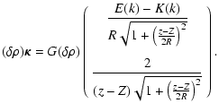 |
|
|
(24) |
It can be shown (see the proof in the Appendix A) that
 is finite at the coincident point, namely
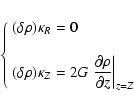 |
(25) |
for k=1. This means that the integrands in Eq. (23) are regular over the whole range [-h,h]. It follows that
 can be estimated with standard integration schemes, for any a, any R, any Z and for any mass density profile. Since
 is known, the secondary kernel
 can be easily determined. Note that vertical partial derivatives
 are in principle needed in this procedure (unless a dynamial mesh is implemented; see Sect. 3.5).
![\begin{figure}
\par\includegraphics[width=8.1cm,clip]{0194fig4.eps}\end{figure}](/articles/aa/full/2005/16/aa0194-03/Timg114.gif) |
Figure 4:
Illustration of the density splitting method. The cylinder a) has radius a=1, semi-thickness H=1, and the mass density  follows a parabolic law b). The field point has arbitrarily coordinates R=a and
 .
There, both integrands .
There, both integrands
 and
and
 diverge c).
 |
| Open with DEXTER |
Let us now illustrate the method step by step, graphically. Figure 4a shows a cylinder with radius a=1 and total height 2H=2, carrying a parabolic density profile that satisfies the assumptions listed in Sect. 2.2. This profile is plotted in Fig. 4b. As field point, we choose arbitrarily the point with coordinates R=a and
 .
There, both integrands
 and
and
 diverge because of the loop singularity. These two quantities are displayed in Fig. 4c. At the field point, the density takes the value
 .
The residual density
 is plotted in Fig. 5a. The "field'' due to a cylinder with constant density
  (that is
 )
is known in a closed form. So, the contribution due to
 remains to be computed numerically. Components of the residual integrand
 are shown in Fig. 5b. We see that these are regular functions, in particular at the field point. Subsequently, standard quadrature schemes can furnish the residual secondary kernel
 ,
and the total secondary kernel is found from Eq. (22).
![\begin{figure}
\par\includegraphics[width=8.3cm,clip]{0194fig5.eps}\end{figure}](/articles/aa/full/2005/16/aa0194-03/Timg117.gif) |
Figure 5:
Illustration of the density splitting method (continued). By construction a), the "residual'' profile
 vanishes at the field point, where the mass density at the field point
  .
The "residual'' integrands b) are finite, and can be integrated numerically with standard schemes. In the homogeneous limit, the method is exact. .
The "residual'' integrands b) are finite, and can be integrated numerically with standard schemes. In the homogeneous limit, the method is exact. |
| Open with DEXTER |
3.5 Vertical sampling: A dynamical mesh
We now have a problem of numerical quadrature. As usual, efficient rules that minimize the amount of source points and maximize the precision should be preferred. Several techniques can be considered, such as local quadrature rules or collocation methods. Here, we use a sampling function, denoted w(z), in order to enhance the number of source points around the coincident point in combination with the high-order![[*]](/icons/foot_motif.gif) , irregular step quadrature rule of Gill & Miller (1972).
Many choices are possible for w(z). Preliminary tests have shown that an appropriate function is
, irregular step quadrature rule of Gill & Miller (1972).
Many choices are possible for w(z). Preliminary tests have shown that an appropriate function is
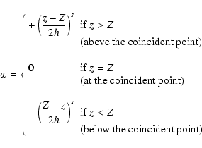 |
(26) |
where s is a parameter. We shall discuss later what this choice implies in terms of the physical resolution (i.e. the smallest size that can be resolved vertically).
Provided 0 < s < 1, a regular spacing in the w-variable produces the required enhancement of the number of source points around z=Z. In other words, for M sources points located in the domain [-h,h], we have for the coincident cylinder
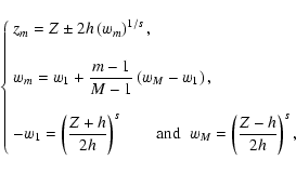 |
(27) |
for
 ,
where one of the zm equals Z.
For most situations, we have noticed that the choice
 appears the best choice for both
 and
and
 ,
and we work with this default value in the following. Note that the integral
 in Eq. (23) can be converted into the form
 .
Since
 at w=0, we have
 at the coincident point. As a consequence, the vertical derivatives
 are no longuer needed (see Eq. (25), and see Appendix A, Eq. (A.4)).
Table 1:
Two mass density/shape models considered in this study. For model
9
1, an exact expression for both
 and gZ can be derived analytically from Eqs. (8) and (9) provided
 (see the Appendix B, Eq. (B.2); the kernel and field are finite for
 ). Model 2 is a vertically parabolic profile. In this case, there is no solution in a closed form, whatever the shape of the system. Note that
 for
for  whereas
 for
for  .
.
![\begin{figure}
\par\includegraphics[width=8.4cm,clip]{0194fig6.eps}\end{figure}](/articles/aa/full/2005/16/aa0194-03/Timg135.gif) |
Figure 6:
Top panel: error index
 versus the number of vertical source points M, obtained for a cylinder with radius a=1 and density profile
  (see Table 1). Four semi-thicknesses are considered:
H=10-4, 0.01, 0.1 and 1. The field point has coordinates R=a, and
 .
Bottom panel: error index obtained in the same conditions as above for h=1 ( plane line) compared with density/shape model 2 ( symbols). .
Bottom panel: error index obtained in the same conditions as above for h=1 ( plane line) compared with density/shape model 2 ( symbols). |
| Open with DEXTER |
3.6 Method checking
To check the density splitting method at this intermediate level (i.e. before performing the radial integration) as well as its accuracy, we need vertical test profiles for which the corresponding secondary kernel is exactly known. For a proper and fair check, it is necessary that test-densities do not vanish just at the coincident point. This would imply that there is no kernel singularity, and thus no homogeneous contribution (i.e.
 ). We shall restrict ourselves to the vertical component because of the simple form of the kernel
  that enables us to easily find "density/secondary kernel'' pairs. Also, to shorten the discussion, we report a single test, although we have successfully checked many. We give in Table 1 two models for the density profile and shape. Let us first consider model
![[*]](/icons/foot_motif.gif) 1. We can thus compare the reference value corresponding to
1. We can thus compare the reference value corresponding to  ,
denoted
 ,
to values obtained from the density splitting method. In the following, comparisons are made with the "error index''
 defined as
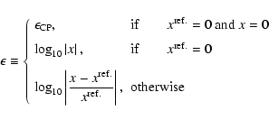 |
(28) |
where
 corresponds to the typical computer precision (generally
  -14 for double precision), x is some quantity and
 denotes the reference value (supposed to be better than x). Figure 6a displays the error index
 versus
 .
As above, we have considered a cylinder with radius a=1, but four different aspect ratios
 ,
10-2, 0.1 and 1. We see that a relative precision ranging from
  10-3 to 10-12 (depending on the aspect ratio
 )
is reached for only 10 source points, which is remarkable. This is essential regarding the computing time. Unsurprisingly, the smaller the aspect ratio, the larger the precision for a given M. We also see that the precision is limited by effects due to the computer maximal precision for about a hundred points in the case with
 .
Due to the quadrature scheme, the method response is roughly given by the formula
 |
(29) |
which means almost two more digits fixed for two times more points. Note that 2nd order centered schemes would give
 for the field components from Eqs. (1) and (3), and whatever the vertical extent.
Figure 6b shows the results obtained in the same conditions as above but for the density/shape model 2 reported in Table 1 which corresponds to a parabolic vertical profile, an astrophysically more realistic case. The error index for both the radial and vertical components is plotted. Since exact values of the secondary kernels are not known in this case, we take as references
 and
and
 ,
values computed for very large M such that all the available digits are fixed and stationary (because of the order of the present quadrature scheme, doubling the resolution would suffice).
We see that there is almost no difference between models 1 and 2.
We have checked many density profiles and have noticed that the performances of the splitting method indeed hold. Applying the splitting method outside the cylinder
,
values computed for very large M such that all the available digits are fixed and stationary (because of the order of the present quadrature scheme, doubling the resolution would suffice).
We see that there is almost no difference between models 1 and 2.
We have checked many density profiles and have noticed that the performances of the splitting method indeed hold. Applying the splitting method outside the cylinder![[*]](/icons/foot_motif.gif) , that is for
, that is for  (and
(and  ), gives much better results (i.e.
 is reached for fewer source points), unsurprisingly.
![\begin{figure}
\par\includegraphics[width=8.4cm,clip]{0194fig7.eps}\end{figure}](/articles/aa/full/2005/16/aa0194-03/Timg153.gif) |
Figure 7:
Typical shape of secondary kernels
 ( left panels) and
 ( right panels) versus a at two different scales for a flat disc, with inner edge
 ,
outer edge ,
outer edge
 and thickness 2H=2. The area under each curve ( shaded zones) gives the field components.
The location of the N cylinders as specified by the v-function is marked by circles.
The radial extension of the peaks is a few local thicknesses. Units are arbitrary.
 |
| Open with DEXTER |
4 Field values
4.1 Radial sampling
The radial integration of the secondary kernel
 according to Eq. (11) is the second and last step. This operation is less tricky since it has regular components
![[*]](/icons/foot_motif.gif) .
We shall proceed as in the previous section, through a sampling function in order to set the position of the N cylinders in the range
.
We shall proceed as in the previous section, through a sampling function in order to set the position of the N cylinders in the range
![$[a_{\rm in}, a_{\rm out}]$](/articles/aa/full/2005/16/aa0194-03/img157.gif) in an adequate manner (see Fig. 3), and using the same quadrature rule. Let us call v(a) this function. For systems with
in an adequate manner (see Fig. 3), and using the same quadrature rule. Let us call v(a) this function. For systems with
 (i.e. for compact systems like tori), we could employ a formula similar to w(z). However, such a choice is not appropriate for general purposes, especially for geometrically thin and extended systems. We stress that the self-gravitating field is determined by two contributions:
- a "local'' contribution, due to the matter located in the neighborhood of the coincident cylinder. The corresponding secondary kernel is very narrow but has large amplitude;
- a "long-range'' contribution, due to the matter located far away. The secondary kernel is very wide, but has a tiny amplitude.
This is illustrated in Fig. 7. Both the local and long-range contributions can have comparable magnitude. As a consequence, the v-function must be such that the sampling of cylinders is good enough not only in the neighborhood of the coincident cylinder (i.e. for
 )
but also far from it. This is achieved with the following piece-wise sampling-function
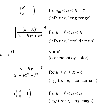 |
(31) |
where  and q are free parameters. In particular,
  must typically represent a few vertical local thicknesses or a fraction of it (depending on the system aspect ratio and radial, density gradients), that is
 .
With
 ,
the number of cylinders is increased around the coincident cylinder with a regular v-mesh, namely
![\begin{displaymath}\left\{\begin{array}{ll}
a_n = R \left(1+e^{\pm v_n}\right)^{...
... \right]^q&\mbox{(local domain)},
\\ [4mm]
\end{array}\right.
\end{displaymath}](/articles/aa/full/2005/16/aa0194-03/img165.gif) |
(32) |
for
 ,
where one of the an equals R.
In practice, the value
 is well suited for general use. We impose only the number
 of cylinders populating the local domain, and then determine the number of cylinders belonging to the left-side and right-side long-range domains (denoted
 and
and
 respectively) in such a way that v has continuous derivatives at the long-range/local connection. Thus, N is an output quantity. The detail of these settings is found in Appendix C.
We have checked the method for various tri-dimensional configurations. Here are a few typical examples involving the three systems listed in Table 2. Systems 1 and 2 are perfectly flat objects, whereas system 3 is a flared, extended disc. Figure 8 shows the error index
 (see Eq. (28)) and the number N of cylinders for systems 1 and 2 with density/shape model 1 (see Table 1). In this case, the reference field
 is known. Computations have been performed for M=8, 16, 32, 64 and 128 vertical source points (for all cylinders). We see that the accuracy is fully tunable, and can be extremely high. For system 1, a hundred points in each direction yield a relative precision of
  10-11 on average (this would be
  10-2 using a 3-point, finite difference scheme). Due to the present quadrature rule, the relative precision is improved by two orders of magnitude when both N and M are doubled. The more compact the system, the more efficient the method for a given grid size
 .
Again, the remarkable issue is that, with a few points only, the relative precision is already good. For instance for system 1, a
 grid yields
 (this is achieved with a
 size grid for system 2).
Table 2:
Three systems to check the full method.
![\begin{figure}
\par\includegraphics[width=8.4cm,clip]{0194fig8.eps}\end{figure}](/articles/aa/full/2005/16/aa0194-03/Timg178.gif) |
Figure 8:
Number N of cylinders ( top panels) and error index
 on the vertical field ( middle panels) for the density/shape model 1 (see Table 1) and systems 1 ( left) and 2 ( right) for which characteristics are listed in Table 2. The altitude of the field point is
 .
The vertical field is also given ( bottom panels). .
The vertical field is also given ( bottom panels). |
| Open with DEXTER |
Figure 9 displays the results obtained in the same conditions but for system 3 and for model 2 for the density and shape. This case is typical of a certain class of astrophysical discs![[*]](/icons/foot_motif.gif) . As in Sect. 3.6, unknown reference values for gR and gZ have been estimated using a larger number of source points. We see that the global trends are identical, suggesting the "universal'' character of the method performance. In general, we find that the accuracy is mainly sensitive to M (and weakly to N, thanks to the dynamical mesh), with roughly
. As in Sect. 3.6, unknown reference values for gR and gZ have been estimated using a larger number of source points. We see that the global trends are identical, suggesting the "universal'' character of the method performance. In general, we find that the accuracy is mainly sensitive to M (and weakly to N, thanks to the dynamical mesh), with roughly
 |
(33) |
for each field component. Obviously, density/shape models considered here as tests are smooth functions, and so these performances have some limits. In other hand, any method that would not behave well in the presence of smooth distributions would apply in special conditions.
![\begin{figure}
\par\includegraphics[width=8.4cm,clip]{0194fig9.eps}\end{figure}](/articles/aa/full/2005/16/aa0194-03/Timg182.gif) |
Figure 9:
Same legend and same conditions as for Fig. 8 (except
 )
but for a geometrically thin and flared disc (system 3) with density/shape model 2 (see Table 1). )
but for a geometrically thin and flared disc (system 3) with density/shape model 2 (see Table 1). |
| Open with DEXTER |
5 Numerical treatment of the self-gravitating potential: The "double splitting'' method
5.1 Kernels and potentials
Let us now consider the potential. Following the formalism employed in Sect. 2, the potential  due to an infinitely thin, homogeneous circular loop (see Fig. 1) with linear mass
  and radius a is (e.g. Durand 1964)
 |
(34) |
where the kernel
 is given by
 |
(35) |
Then, for any tri-dimensional, axially symmetric system with mass density  ,
the potential can be written in the form
 |
(36) |
where
 |
(37) |
is the secondary kernel.
![\begin{figure}
\par\includegraphics[width=17cm,clip]{0194fig10.eps}\end{figure}](/articles/aa/full/2005/16/aa0194-03/Timg188.gif) |
Figure 10:
Same legend and same conditions as for Figs. 8 and 9 but for the potential  (see text for more details).
 |
| Open with DEXTER |
We see from Eq. (35) that the straightforward determination of the secondary kernel
 is problematic because of the loop singularity.
In order to compute this quantity everywhere and especially at the coincident point, we shall use a slightly different approach than for the field. Actually, we failed to determine an analytical expression for a density field, non-vanishing at the coincident point and such that Eq. (37) is known in a closed form. The choice of a z-independent mass density
  as considered in Sect. 3.2 does not help here. Since the asymptotic form of the K-function as
 is known, we first set
 |
(38) |
where
 denotes the "regular'' complete elliptic integral of the first kind. This function is plotted versus k in Fig. 2. It is a smooth, regular function in the range [0,1]. Given this "kernel splitting'', Eq. (37) is
 |
(39) |
where
 |
(40) |
is the regular part, and
 |
(41) |
is the remaining, singular part. We see that
 can be determined numerically without problems since the integrand in Eq. (40) is regular in any case. The singularity remains but it is now in Eq. (41), in an explicit form.
We can now use the analogue of the "density splitting'' method to compute
 .
We set
 and split this quantity into two terms according to
 |
(42) |
For the coincident cylinder (i.e. m=1), this relation becomes
 |
(43) |
where
 is the mass density just at the field/coincident point, and
 is the residual profile, i.e. deviation to the local value. Under these conditions, Eq. (41) is
 |
|
|
(44) |
The first term in the right-hand-side of this equation is known (see Appendix D). The second term (the "residual kernel''
 )
can easily be determined numerically using standard quadrature rules since
 at the field point despite
 (the proof that can be made from a Taylor expansion about z=Z; see for instance Appendix A).
5.4 Method checking
We give here a few examples to prove the efficiency of the double splitting method for the potential. To abridge the discussion, we shall not report tests made on the secondary kernel
 (relative precisions are similar to Sect. 3.6).
Figure 10 is the analogue of Figs. 8 and 9: it displays the error index
 obtained for systems 1, 2 and 3 as already considered before (see Table 2). For these three systems, the "exact'' potential being not known, we take as reference potentials
 ,
values determined by enhancing the numerical resolutions. Graphs show that, in all cases, the relative precision on the potential is excellent with a few source points. Issues raised for the field components hold here. In particular, Eq. (33) applies, with the same weak dependence on N.
![\begin{figure}
\par\includegraphics[height=7.8cm,bb=224 229 359 580, clip=,angle...
...cs[height=7.8cm,bb=224 229 395 580, clip=,angle=-90]{0194fig13.eps} \end{figure}](/articles/aa/full/2005/16/aa0194-03/Timg205.gif) |
Figure 11:
Mass density  ( top) and potential
  ( middle) and error index
 ( bottom) for an inviscid, self-gravitating polytrope at equilibrium with index
  and axis ratio 0.5.
 |
| Open with DEXTER |
5.5 An example of astrophysical application: Equilibrium of a compressible Dyson-ring
To illustrate the method in a concrete case, we consider the classical problem of uniformly rotating, inviscid polytropes. For such a system, the equilibrium structure is governed by the following two equations (e.g. Hachisu 1986)
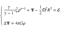 |
(45) |
where
 is the polytropic index,
  is the rotation frequency at any point of the fluid, and
  and
and  are constants. Once
  ,
,
 ,
,
 and
and  are prescribed, the solution of the above system can be determined using the Self-Consistent Field (SCF) method (Ostriker & Mark 1968). Figure 11 shows the equilibrium mass density, potential and associated error index
 for a polytropic index
  and axis ratio
 ,
a case considered in Hachisu (1986). In this example,
  is deliberately computed with a small size, dynamical grid containing about
 density points. The error index is compatible with results shown in Fig. 10: the relative precision on the potential inside the source cannot be better
than
  10-6 for the actual grid size. Our results are however in good agreement with Hachisu's work within a few percent typically, despite a different technique
![[*]](/icons/foot_motif.gif) and in particular much fewer source points. Higher precisions are obtained with finer grids.
and in particular much fewer source points. Higher precisions are obtained with finer grids.
5.6 Potential and field on the z-axis
On the z-axis,
 and
and  are no more singular, for any a, with the consequence that the secondary kernels can easily be determined, in principle without the need for density splitting (see however note 10). From Eqs. (12) and (37), we have
![\begin{displaymath}\breve{\kappa}_Z = 2 \pi G \int_{-H}^H{\frac{\rho a(z-Z){\rm d}z}{\left[a^2+ (z-Z)^2\right]^{3/2}}}
\end{displaymath}](/articles/aa/full/2005/16/aa0194-03/img216.gif) |
(46) |
and
 |
(47) |
respectively. It follows that the homogeneous contributions are simply given by
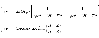 |
(48) |
and the corresponding residual secondary kernels are
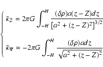 |
(49) |
where
 .
Figure 12 gives a concrete illustration of this case.
![\begin{figure}
\par\includegraphics[width=8.3cm,angle=0,clip]{0194fig14.eps} \end{figure}](/articles/aa/full/2005/16/aa0194-03/Timg221.gif) |
Figure 12:
Accuracy of the vertical field gZ on the z-axis for a flat, homogneous disc with inner edge
 ,
outer edge ,
outer edge
 ,
and three different semi-thickness H. The altitude of the field point is Z=H/2. ,
and three different semi-thickness H. The altitude of the field point is Z=H/2. |
| Open with DEXTER |
6 Resolutions and efficiency
There is a relationship between the number of source points M on a given cylinder, the s-parameter and the physical resolution
 in the vertical direction, namely
 |
(50) |
for the coincident cylinder, where
 is the distance between two neighboring source points (
![$m \in [1,M-1]$](/articles/aa/full/2005/16/aa0194-03/img224.gif) ). From Eq. (26), we have
). From Eq. (26), we have
 |
(51) |
where
![$\displaystyle \Delta w = \frac{1}{(2h)^s} \left[ (h-Z)^s+(h+Z)^s \right].$](/articles/aa/full/2005/16/aa0194-03/img226.gif) |
|
|
(52) |
Two extreme cases can be considered: the resolution at the field point (where
 ), and the resolution far from it (i.e.
 ).
Table 3 gives the expected expression for
 depending on the local disc aspect ratio
 ,
and gives a few typical examples. We see that there is always a large resolution at the field point, much larger than allowed in finite-difference methods for the same M. This always ensures that the secondary kernel is determined with a certain accuracy.
Table 3:
Theoretical formulae for the physical resolution
 in the vertical direction as functions of the number M of source points,s-parameter and disc semi-thickness h. The last column corresponds to a 3-point, finite-difference method.
Table 4:
Same legend as for Table 3 but for the physical resolution
 in the radial direction (
 for all examples).
 ,
,
 and
and
 denote the number of cylinders populating the left-side, long-range, the local and right-side, long-range contributions respectively (see the Appendix C).
A similar analysis can be led in the radial direction where the physical resolution is defined by
 |
(53) |
where
 is the radial extent of the system, and
 is the distance between two adjacent cylinders (
![$n \in [1,N-1]$](/articles/aa/full/2005/16/aa0194-03/img267.gif) ). From Eq. (31), we find
). From Eq. (31), we find
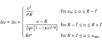 |
(54) |
where  may depend on the domain.
Table 4 gives the theoretical formula for
 depending on the location inside the system. Five key-positions are considered: near the inner edge, at the field point, near the outer edge, and at the connection between the long-range and local contributions. A few typical values of given. Again, due to the dynamical mesh, the resolution is very large at the field point. This is specially pronounced for very extended and flat systems since
 .
.
6.3 Efficiency: Computing time/precision ratio
Intrinsically, finite difference methods (FDMs) are known to be extremely fast compared to integral methods (IMs). But comparing methods together has sense only if their accuracy as well as their ability for finding solutions ab nihilo for various kinds of systems are considered too
 .
On this basis, best methods must i) be "self-starting''; ii) have low execution times
  ;
iii) be highly accurate (i.e. low
  values); and iv) be able to treat any shape. For astrophysical discs, tori and rings, conditions i) and iv) are not satisfied by FDMs (because FDMs cannot start without boundary conditions, and because grid meshes generaly do not exactly fit the system surfaces). Regarding points ii) and iii), the efficiency
  of a method can be defined as
 |
(55) |
and the larger  ,
the more efficient the method
,
the more efficient the method![[*]](/icons/foot_motif.gif) . Let us estimate
. Let us estimate  in both cases, assuming for simplicity a compact system (i.e.
  )
and a square grid (i.e. M=N).
A 5-point finite difference method is characterized by a computing time
 (e.g. Swarztrauber & Sweet 1996), once initialized. The preliminary determination of boundary conditions (BCs) from an integral method implies an additional time
 generally much larger than for the inversion of the Laplacian. Their relative error corresponds to
 for the potential (and only M-1 for the field components). For integral methods,
 in general. With the actual quadrature scheme, we have
 (see previous sections). So, regarding the potential, efficiencies are
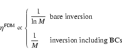 |
(56) |
and
 |
(57) |
respectively. As a result,
 |
(58) |
making the present method more efficient in the limit of large M (and this is true for any integral method with
 ). We have verified this issue experimentally
![[*]](/icons/foot_motif.gif) for different configurations, different shapes and density profiles. Figure 13
gives the efficiency
for both methods
for different configurations, different shapes and density profiles. Figure 13
gives the efficiency
for both methods
 observed for system 1 and density/shape model 2 with
 as already considered (see Tables 1 and 2, and Figs. 8-10), forcing M=N. These results are typical for compact systems, like tori and thick discs.
In this example, we see that the present method is more efficient as soon as
 if we account for the fact that FDMs are not self-starting methods which is always the case for systems of interest here. Regarding field values, a similar analysis shows that
 is unchanged whereas
 ,
with the consequence that Ineq. (58) still holds and even is better satisfied.
![\begin{figure}
\par\includegraphics[width=8.4cm, clip=]{0194fig15.eps}\end{figure}](/articles/aa/full/2005/16/aa0194-03/Timg289.gif) |
Figure 13:
Experimental efficiencies  to compute the potential in a square,
 computational grid with a 5-point finite difference method (FDM) and with the present (double splitting) method for system 1 and density/shape model 2 (see text).
 |
| Open with DEXTER |
The ratio
 gets larger i) as the system aspect ratio H/a decreases, and ii) as the system extension
 increases. In particular, Eq. (57) does not account for the dynamical mesh. For large and flat systems, FDMs need a drastic reduction of the mesh size in the radial direction in order to reach a given precision, since
![$\epsilon^{\rm FDM} \approx 2 \log_{10} \left[ {\rm Sup} \{ \frac{H}{M}, \frac{L}{N} \} \right]$](/articles/aa/full/2005/16/aa0194-03/img291.gif) for the potential. This means a considerable increase of the computing time. For instance, for system 2 where
for the potential. This means a considerable increase of the computing time. For instance, for system 2 where
 and
and
 (see Table 2 and Fig. 10),
 is required to obtain everywhere a relative precision on
  of the order of
 only. As a result,
 is inevitably multiplied by a huge factor (
 1010 typically). Such a runaway is totally avoided in the present method, thanks to the dynamical mesh (note that
  is attained with less than a hundred points in the radial direction). As shown in previous sections, N never greatly exceeds M, so that
 is not very sensitive to the system size.
We have presented efficient numerical (splitting) methods to compute the field and the potential inside axially symmetric sources. The implementation of a dynamical mesh together with a high-order quadrature scheme enables a very accurate determination of Poisson integrals for a wide variety of system shapes and sizes. Performances and convincing tests have been reported. We have derived all necessary formulae to make the implementation of the method into various codes easier.
Improvement, modifications and extensions of this work are obviously possible. For instance, better results can probably be obtained by considering different quadrature rules and/or other sampling functions. In particular, it would be interesting to enhance the concentration of source points not only around the field point, but in all regions of the system where the density field could exhibit important gradient variations. We have always assumed (for simplicity) that all cylinders have vertically the same number M of source points. Since the field and the potential decrease quite rapidly with the separation, it is conceivable to use a small number of source points for cylinders located (very) far away from the coincident cylinder (depending on the density distribution). This can be advantageous in terms of computing time. The challenge is then to find the most appropriate distribution M(a) without losing the precision.
The major assumption made here is axial symmetry which, for some problems, is too restrictive. The splitting method can easily be extended to non-axisymmetric configurations. Actually, in a fully tri-dimensional case, Eq. (21) can be generalized as follows
 |
(59) |
where
 is the mass density at the field point
 ,
and
,
and
 is the non-axially-symmetric, residual distribution which satisfies
 by construction. It then "suffices'' to integrate this residual distribution according to Eq. (4) (which has a regular integrand when
 ), augmented with the contribution due to the axially symmetric cylinder with density
  ,
from Eq. (14).
Acknowledgements
I am grateful to S. Bonazzola for enlightening discussions both on mathematical and physical aspects of the problem. I thank my colleagues R. Grappin, V. Karas, J. Léorat, M. Mouchet, D. Pelat, A. Pierens and L. Subr for many comments and suggestions. I thank the referee Howard Cohl for valuable comments and suggestions.
Appendix A: Values of
 at the coincident point
For a correct numerical treatment of Eq. (23), it is necessary to know exactly
 at the coincident point. This can be done by considering Eq. (24) in the limit where
 .
Since
 by construction at the coincident point, a Taylor expansion of
 around z=Z at all orders gives
where
 due to Eq. (21). For m=1, we have
 |
(A.2) |
and
 .
Since E is bounded, we have
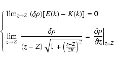 |
(A.3) |
with the consequence that
 is finite at the coincident point, with
 |
|
|
(A.4) |
For  along the coincident cylinder,
 is given by Eq. (24).
Appendix B: Density/secondary kernels test-pairs
For density model 1 given in Table 1, the secondary kernel associated with the vertical component is
 |
(B.1) |
This secondary kernel can then be integrated analytically in the radial direction, depending on the shape H(a). For
 (i.e. a flat system), we have
Appendix C: Input parameters for the radial sampling
The total number of cylinder is defined as follows. First, we decide the number of cylinders standing in the domain
![$[R-\ell, R+\ell]$](/articles/aa/full/2005/16/aa0194-03/img322.gif) ,
say
,
say
 cylinders. The regular spacing of the v in this range then yields the location an of the cylinders that form the local contribution.
In the local contribution, Eq. (54) reads
 |
(C.1) |
depending on the sign of v. For a regular sampling in v,  is given by
 |
(C.2) |
where
 is the total number of cylinders in the local contribution. In particular,
  can be computed at
 .
.
Second, we determine the number of cylinders populating the long-range domains (
 and
and
 for the left-side and right-side respectively), such that the radial sampling
  has continuous derivatives at
 .
We find
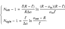 |
(C.3) |
The radius an of these remaining cylinders is then obtained from regular spacing of the v-variable (see Eq. (31)). The total number of cylinders is then
 |
(C.4) |
Appendix D: Analytical formula
We have
 |
(D.1) |
Since
 |
|
|
(D.2) |
we have
where

- Abramowitz, M., &
Stegun, I. A. 1964, in Handbook of mathematical functions with
examples, graphs and mathematical tables, NBS, Sect. 17
- Adams, F. C., Ruden, S.
P., & Shu, F. H. 1989, ApJ, 347, 959 [NASA ADS] [CrossRef] (In the text)
- Adams, J., Swarztrauber,
P., & Sweet, R. 1980, fishpack/NETLIB/NCAR
- Ansorg, M.,
Kleinwächter, A., & Meinel, R. 2003a, MNRAS, 339, 515 [NASA ADS] [CrossRef] (In the text)
- Ansorg, M.,
Kleinwächter, A., & Meinel, R. 2003b, ApJ, 582, L87 [NASA ADS] [CrossRef] (In the text)
- Bodo, G., & Curir, A.
1992, A&A, 253, 318 [NASA ADS] (In the text)
- Bonazzola, S., &
Schneider, J. 1974, ApJ, 191, 273 [NASA ADS] [CrossRef] (In the text)
- Bonazzola, S.,
Gourgoulhon, E, & Marck, J.-A. 1998, Phys. Rev. D, 58,
104020 [NASA ADS] [CrossRef] (In the text)
- Borges, L., & Daripa,
P. 2001, JCP, 169, 151 [NASA ADS] (In the text)
- Binney, J., &
Tremaine, S. 1987, in Galactic dynamics (Princeton, NJ: Princeton
University Press)
(In the text)
- Chen, H., Su, Y., &
Shizgal, B. D. 2000, JCP, 160, 453 [NASA ADS] (In the text)
- Christopher, I., Knorr,
G., Shoucri, M., & Bertrand, P. 1997, JCP, 131, 323 (In the text)
- Clément, M. J. 1974,
ApJ, 194, 709 [NASA ADS] [CrossRef] (In the text)
- Cohl, H. S., &
Tohline, J. E. 1999, ApJ, 527, 86 [NASA ADS] [CrossRef] (In the text)
- Cohl, H. S. 1999, Ph.D.
Thesis
- Durand, E. 1964, in
Electrostatique. I. Les distributions (Masson)
(In the text)
- Gill, P. E., &
Miller, G. F. 1972, Comput. J., 80
(In the text)
- Greengard, L., & Lee,
J. Y. 1996, JCP, 125, 415 (In the text)
- Hachisu, I. 1986, ApJS,
62, 46 [NASA ADS] (In the text)
- Lai, M., Lin W., &
Wang W. 2002, JNA, 22, 537 (In the text)
- Müller, E., &
Steinmetz, M. 1995, Comp. Phys. Commun., 89, 45 [NASA ADS] (In the text)
- Pierens, A., &
Huré, J.-M. 2005, A&A, 434, 17 [EDP Sciences] [CrossRef] (Paper II)
(In the text)
- Störzer, H. 1993,
ApJ, 271, 25 [NASA ADS] (In the text)
- Swarztrauber, P., &
Sweet, R. 1996, in Handbook of fluid dynamics and Fluid Machinery,
ed. J. A. Schetz, & A. E. Fuhs (New-York: J. Wiley &
Sons)
(In the text)
Copyright ESO 2005


![\begin{figure}
\par\includegraphics[width=8.3cm,clip]{0194fig1.eps}\end{figure}](/articles/aa/full/2005/16/aa0194-03/Timg47.gif)

![\begin{displaymath}\kappa_R = \frac{G}{R} \sqrt{\frac{a}{R}} k \left[ E(k)- K(k) + \frac{(a-R)k^2 E(k)}{2 a{k'}^2} \right],
\end{displaymath}](/articles/aa/full/2005/16/aa0194-03/img56.gif)


![\begin{figure}
\par\includegraphics[width=16.8cm,clip]{0194fig3.eps}\end{figure}](/articles/aa/full/2005/16/aa0194-03/Timg69.gif)


![$\displaystyle -2 G \rho_0 \sqrt{\frac{a}{R}}
\left(\begin{array}{c}
\displaysty...
...(Z+H)}{2R} k^- \Lambda(m,k^-)\\ [4mm]
k^+ K(k^+) - k^-K(k^-)\end{array}\right)$](/articles/aa/full/2005/16/aa0194-03/img86.gif)


![\begin{displaymath}\vec{\breve{\kappa}}^{(0)} = - 2 G \rho_0
\left(\begin{array}...
...{k'}^-}\right]\\ \\
k^+ K(k^+) - k^-K(k^-)\end{array}\right).
\end{displaymath}](/articles/aa/full/2005/16/aa0194-03/img101.gif)


![\begin{figure}
\par\includegraphics[width=8.1cm,clip]{0194fig4.eps}\end{figure}](/articles/aa/full/2005/16/aa0194-03/Timg114.gif)


![\begin{figure}
\par\includegraphics[width=8.4cm,clip]{0194fig6.eps}\end{figure}](/articles/aa/full/2005/16/aa0194-03/Timg135.gif)


![\begin{figure}
\par\includegraphics[width=8.4cm,clip]{0194fig7.eps}\end{figure}](/articles/aa/full/2005/16/aa0194-03/Timg153.gif)

![\begin{displaymath}\left\{\begin{array}{ll}
a_n = R \left(1+e^{\pm v_n}\right)^{...
... \right]^q&\mbox{(local domain)},
\\ [4mm]
\end{array}\right.
\end{displaymath}](/articles/aa/full/2005/16/aa0194-03/img165.gif)
![\begin{figure}
\par\includegraphics[width=8.4cm,clip]{0194fig8.eps}\end{figure}](/articles/aa/full/2005/16/aa0194-03/Timg178.gif)

![\begin{figure}
\par\includegraphics[width=8.4cm,clip]{0194fig9.eps}\end{figure}](/articles/aa/full/2005/16/aa0194-03/Timg182.gif)


![\begin{figure}
\par\includegraphics[width=17cm,clip]{0194fig10.eps}\end{figure}](/articles/aa/full/2005/16/aa0194-03/Timg188.gif)


![\begin{figure}
\par\includegraphics[height=7.8cm,bb=224 229 359 580, clip=,angle...
...cs[height=7.8cm,bb=224 229 395 580, clip=,angle=-90]{0194fig13.eps} \end{figure}](/articles/aa/full/2005/16/aa0194-03/Timg205.gif)

![\begin{displaymath}\breve{\kappa}_Z = 2 \pi G \int_{-H}^H{\frac{\rho a(z-Z){\rm d}z}{\left[a^2+ (z-Z)^2\right]^{3/2}}}
\end{displaymath}](/articles/aa/full/2005/16/aa0194-03/img216.gif)


![\begin{figure}
\par\includegraphics[width=8.3cm,angle=0,clip]{0194fig14.eps} \end{figure}](/articles/aa/full/2005/16/aa0194-03/Timg221.gif)


![\begin{figure}
\par\includegraphics[width=8.4cm, clip=]{0194fig15.eps}\end{figure}](/articles/aa/full/2005/16/aa0194-03/Timg289.gif)


![$\displaystyle \left. + (z-Z)\sum_3^{\infty}{\frac{(z-Z)^{i-2}}{i!}\left.\frac{\partial^i \delta \rho}{\partial z^i}\right\vert _{z=Z}} \right]$](/articles/aa/full/2005/16/aa0194-03/img309.gif)


![$\displaystyle \left. -2(H+Z) \left( {\rm atan ~}\frac{a-R}{H+Z} - {\rm atan ~}\frac{a+R}{H+Z}\right) \right]_{a_{\rm in}}^{a_{\rm out}}\cdot$](/articles/aa/full/2005/16/aa0194-03/img321.gif)


