A&A 443, 1047-1053 (2005)
DOI: 10.1051/0004-6361:20052935
C. Beck1 - R. Schlichenmaier1 - M. Collados2 - L. Bellot Rubio1,3 - T. Kentischer1
1 - Kiepenheuer-Institut für Sonnenphysik,
Schöneckstr. 6, 79104 Freiburg, Germany
2 - Instituto de Astrofísica de Canarias,
via Láctea, La Laguna, Tenerife, Spain
3 - Instituto de Astrofísica de Andalucía,
Apdo. 3004, 18080 Granada, Spain
Received 25 February 2005 / Accepted 21 July 2005
Abstract
It is essential to properly calibrate the polarimetric
properties of telescopes, if one wants to take advantage of the
capabilities of high precision spectro-polarimeters.
We have constructed a model for the German Vacuum Tower Telescope (VTT) that
describes its time-dependent polarization properties. Since the
coelostat of the telescope changes the polarization state of the
light by introducing cross talk among different polarization states,
such a model is necessary to correct the measurements, in order to retrieve the true polarization as emitted from the Sun. The telescope model is quantified by a time-dependent Mueller
matrix that depends on the geometry of the light beam through the
telescope, and on material properties: the refractive indices of
the coelostat mirrors, and the birefringence of the
entrance window to the vacuum tube. These material properties were
determined experimentally in-situ by feeding the telescope with known states of polarization (including unpolarized light) and by measuring its response, and from measurements of an
aluminum-coated sample in the laboratory. Accuracy can in our case be determined only for the combination of telescope and spectro-polarimeter used; for the instrument POLIS at the VTT, we estimate an accuracy of ![]() 4-
4-
![]() for the cross talk correction coefficients.
for the cross talk correction coefficients.
Key words: instrumentation: polarimeters - sun: magnetic fields
Polarimeters have been standard instruments at solar telescopes since Hale's discovery that sunspots are manifestations of strong magnetic fields. Due to the easy availability of high-quality polarization optics and of CCD detectors with high quantum-efficiency, polarimeters for the visible or near-infrared spectrum are becoming more frequent in, e.g., stellar and galactical physics as well.
In this contribution we use the German Vacuum Tower Telescope on Tenerife (VTT), a solar telescope, as an example. The VTT is equipped with two spectro-polarimeters that measure the polarization properties at high spatial and spectral resolution: the Tenerife Infrared Polarimeter (TIP, Martínez Pillet et al. 1999), which can be used for almost any line in the near infrared; the Polarimetric Littrow spectrograph (POLIS), which simultaneously measures two neutral iron lines in the visible at 630.2 nm, and the Ca II H line in the near-UV at 397 nm (Schmidt et al. 2001; Beck et al. 2005).
For high precision polarimetric measurements, it is essential to correct for the cross talk among different polarization states which is introduced by reflections on metallic surfaces in the telescope in front of the polarimeter. In this contribution, we describe and then verify an analytical model for the polarimetric properties of a single aluminum-coated mirror surface that uses the complex refractive index of the material as an input parameter. The approach presented can be adjusted to other telescopes for the description of their polarimetric properties; this may be useful if no in-situ measurements are possible, because the refractive index can be measured in an optical laboratory on a sample mirror. We applied the formalism to the optical train of the VTT to derive a time-dependent model of its polarization properties for infrared and visible wavelengths. Polarization models for other solar telescopes have been presented by Balasubramaniam et al. (1985), Capitani et al. (1989), Skumanich et al. (1997), and Bernasconi (1997). Horn et al. (1996) present a Mueller matrix of the VTT for some fixed times (without a model), but it includes both telescope and polarimeter, which makes comparison difficult.
The VTT uses a coelostat to feed the solar light into the telescope. While this guarantees a non-rotating image in the focal plane as the Sun changes its position on the sky, the beam geometry changes during the day and during the year. Hence, it is necessary to develop a model which allows prediction of the polarization properties for a specific configuration. This model is described in Sect. 2. As we will show, the two essential unknowns of this model are the complex refractive index of the two coelostat mirrors and the birefringence of the entrance window. In Sect. 3 we use polarizing sheets to determine the properties of the window. The refractive index is determined in Sect. 4 by two methods: direct measurements in the laboratory (cf. Sect. 4.1) and derivation from the continuum polarization induced by the telescope (Sect. 4.2). In Sect. 5 we present typical results for the Mueller matrix of the telescope, discuss the corresponding errors, and describe the polarimetric calibration procedure as it is applied to TIP and POLIS data.
![\begin{figure}
\par\includegraphics[width=8.3cm,clip]{2935fig1.eps}
\end{figure}](/articles/aa/full/2005/45/aa2935-05/img18.gif) |
Figure 1: Beam geometry of the VTT (sketch not to scale). The coelostat consists of two flat aluminum-coated mirrors (C1 and C2), which feed the light beam into the telescope. M3 is the imaging mirror (f=46 m). M4 folds the light down to the laboratories. E1 and E2 are the entrance and exit windows of the evacuated tube. The Instrument Calibration Unit (ICU) is located below the exit window. |
| Open with DEXTER | |
A sketch of the light beam geometry is displayed in
Fig. 1. The coelostat consists of two flat mirrors (C1 and C2), which feed the beam into the telescope. The second mirror, C2, is mounted on a pillar. Its height depends on the Sun's declination and on the position of C1. C1 can be moved on a circle around C2 while its axis is parallel to the earth rotation axis, e.g., to avoid the shadow of C2 falling on C1. The displacement of C1 from the North-South direction is measured by the angle ![]() ,
which by convention is positive towards the east. C1 is rotated to follow the Sun's track on the sky; i.e., only the angle of incidence on C1,
,
which by convention is positive towards the east. C1 is rotated to follow the Sun's track on the sky; i.e., only the angle of incidence on C1,
![]() ,
is time-dependent for a given position of C1 and C2. The small changes in solar declination during one day produce negligible variations of the angle of incidence on C2,
,
is time-dependent for a given position of C1 and C2. The small changes in solar declination during one day produce negligible variations of the angle of incidence on C2,
![]() .
.
The imaging main mirror, M3, and a folding flat mirror, M4, are contained in a vacuum tube with an entrance and an exit window made of BK7 glass. Just below the exit window the Instrument Calibration Unit (ICU) is installed to calibrate the polarization properties of the remaining light path: the optics of the correlation tracker (CT) system![]() and the instrument itself. The polarimetric calibration of this part of the beam and of the spectro-polarimeter by its response function is described by Beck et al. (2005) for POLIS, and by Schlichenmaier & Collados (2002) and Collados (2003) for TIP.
and the instrument itself. The polarimetric calibration of this part of the beam and of the spectro-polarimeter by its response function is described by Beck et al. (2005) for POLIS, and by Schlichenmaier & Collados (2002) and Collados (2003) for TIP.
In the following, the system of M3, M4, and the two windows will be referred to as "telescope proper'', while the term "whole telescope'' also includes the coelostat.
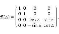
For the telescope model, three effects have to be described quantitatively by Mueller matrices: reflection on a mirror, rotation of the reference frame for the linear polarizations, and transmission through a retarder.
The mirrors at the VTT have plain aluminum coatings with no additional protective layer. The coating device is set up for a coating thickness of 1 ![]() m. For the description of the mirrors, we have adopted a simplified version of the equations for reflection on a metallic surface layer given by Skumanich et al. (1997). We assume (and justify a posteriori) that our aluminum coatings are sufficiently thick for the material properties of the mirror substrate below the coating to have no effect on the reflection. The same applies to the existence of a thin aluminum oxide layer on top of it which forms after the coating process. Three parameters are then needed to calculate the Mueller matrix of a mirror: the angle of incidence,
m. For the description of the mirrors, we have adopted a simplified version of the equations for reflection on a metallic surface layer given by Skumanich et al. (1997). We assume (and justify a posteriori) that our aluminum coatings are sufficiently thick for the material properties of the mirror substrate below the coating to have no effect on the reflection. The same applies to the existence of a thin aluminum oxide layer on top of it which forms after the coating process. Three parameters are then needed to calculate the Mueller matrix of a mirror: the angle of incidence, ![]() ,
and two material properties, the index of refraction,
,
and two material properties, the index of refraction, ![]() ,
and the index of extinction,
,
and the index of extinction, ![]() .
The modified equations are given in Appendix A.
.
The modified equations are given in Appendix A.
The glass of the windows to the evacuated telescope tube is under
tension and might change the polarization state of the beam. In
Sect. 3 we argue that the windows can be described as an
ideal retarder with an effective retardance, ![]() ,
and an
orientation angle of the fast optical axis,
,
and an
orientation angle of the fast optical axis, ![]() ,
which shows a
daily variation.
,
which shows a
daily variation.
The Mueller matrix of the telescope, ![]() ,
results from
subsequently multiplying individual Mueller matrices as the beam
passes through the telescope:
,
results from
subsequently multiplying individual Mueller matrices as the beam
passes through the telescope:
| |
= | ||
| = | |||
| (1) |
The Mueller matrix of the telescope depends (a) on the geometry of the
beam (the angles of incidence on the 4 mirrors,
![]() ,
,
![]() ,
,
![]() ,
and
,
and
![]() ,
the rotation angles,
,
the rotation angles,
![]() ,
,
![]() ,
,
![]() ,
,
![]() )
and (b) on material
properties, i.e. the refraction indices, n, and the extinction
coefficients, k, of the mirrors, and the effective phase shift,
)
and (b) on material
properties, i.e. the refraction indices, n, and the extinction
coefficients, k, of the mirrors, and the effective phase shift, ![]() ,
and angle of the optical axis,
,
and angle of the optical axis, ![]() ,
of the windows. While the
geometry of the beam is deduced in the next subsection, the material
properties are determined by measurements that are described in
Sects. 3 and 4.
,
of the windows. While the
geometry of the beam is deduced in the next subsection, the material
properties are determined by measurements that are described in
Sects. 3 and 4.
The beam path in the telescope proper is fixed by design, and the necessary values are:
| |
= | (2) | |
| = | (3) | ||
| = | (4) |
![\begin{figure}
\par\includegraphics[width=8.4cm,clip]{2935fig2.ps}
\end{figure}](/articles/aa/full/2005/45/aa2935-05/img51.gif) |
Figure 2:
Response of the telescope proper to linearly polarized
light at 630 nm, as the telescope calibration unit was rotated by 180 |
| Open with DEXTER | |
In order to derive the response of the telescope proper, i.e., E1, M3,
M4, and E2, two telescope calibration units (TCUs) were built for
infrared and ultraviolet wavelengths. The TCUs consist of arrays of
rectangular foils, which transmit linearly polarized light. The
polarization axes of the individual foils were all aligned parallel to each other.
To obtain a calibration data set, the TCU is located in front of the
entrance window and is rotated by 180![]() in steps of 10
in steps of 10![]() ,
i.e. 19 measurements are made. The measurements are either performed
with TIP or with POLIS.
,
i.e. 19 measurements are made. The measurements are either performed
with TIP or with POLIS.
Figure 2 displays five data sets that were
recorded with POLIS on July 27, 2003, with C1 at
![]() ,
using the infrared TCU. From top to bottom the four Stokes parameters
,
using the infrared TCU. From top to bottom the four Stokes parameters
![]() ,
Q/I, U/I, and V/I are shown for
5 different times from
the morning (left) to the evening (right). The crosses mark the 19 measurements obtained for each data set. As a comparison, the
solid lines correspond to the results from the telescope model (see
below). At zero degrees the light input consists of pure Q signal,
at
,
Q/I, U/I, and V/I are shown for
5 different times from
the morning (left) to the evening (right). The crosses mark the 19 measurements obtained for each data set. As a comparison, the
solid lines correspond to the results from the telescope model (see
below). At zero degrees the light input consists of pure Q signal,
at ![]() of pure -U and so on. The measured Q and U signals
are in phase with the input signal. Two apparent features need to be
discussed below: (a) The Stokes I dataset exhibits an irregular
pattern, and (b) the telescope proper produces up to 5% of Stokes V. The maximum V signal is reached where U is almost at the maximum, but its position is slightly changing during the day.
In the measurements shown in Fig. 2 the polarization degree,
of pure -U and so on. The measured Q and U signals
are in phase with the input signal. Two apparent features need to be
discussed below: (a) The Stokes I dataset exhibits an irregular
pattern, and (b) the telescope proper produces up to 5% of Stokes V. The maximum V signal is reached where U is almost at the maximum, but its position is slightly changing during the day.
In the measurements shown in Fig. 2 the polarization degree,
![]() ,
is only about 95%. As the depolarization effect of the entrance window should be negligible (cf. Skumanich et al. 1997), we believe this to be a property of the polarizer foils, which have been specified for infrared wavelengths but are used in the visible spectral range. As a check we derived the Mueller matrix of one of the polarizing foils by placing the foil between the Instrument Calibration Unit and the polarimeter itself. The matrix also yielded a transmission of some 5% of unpolarized light.
,
is only about 95%. As the depolarization effect of the entrance window should be negligible (cf. Skumanich et al. 1997), we believe this to be a property of the polarizer foils, which have been specified for infrared wavelengths but are used in the visible spectral range. As a check we derived the Mueller matrix of one of the polarizing foils by placing the foil between the Instrument Calibration Unit and the polarimeter itself. The matrix also yielded a transmission of some 5% of unpolarized light.
As the solid lines in Fig. 2 demonstrate,
measurements with the TCU can be reproduced by the telescope
model. The Mueller matrix of the telescope proper is calculated with
Eq. (B.5) with an effective retardance
of
![]() at 630 nm, and an angle for the fast optical
axis that varies slightly from
at 630 nm, and an angle for the fast optical
axis that varies slightly from
![]() at 8:00 UT to
at 8:00 UT to
![]() at 20:00 UT. From similar measurements with TIP in
the infrared, a retardance value of 1.8
at 20:00 UT. From similar measurements with TIP in
the infrared, a retardance value of 1.8![]() at 1.5
at 1.5 ![]() m was found
which is in reasonable agreement with a
m was found
which is in reasonable agreement with a ![]() dependence of the
retardance value. The telescope proper thus can be reproduced by an ideal retarder with a small retardance. In order to assure this behaviour, the measurements and the corresponding calibration are repeated regularly.
dependence of the
retardance value. The telescope proper thus can be reproduced by an ideal retarder with a small retardance. In order to assure this behaviour, the measurements and the corresponding calibration are repeated regularly.
The measurements were performed for three different wavelengths: 518 nm, 630 nm, and 777 nm. The measurements are displayed in
Fig. 3, together with the resulting least-squares-fits
for the refraction index, n, and the extinction coefficient,
k. The errors due to inaccurate adjustments of the angle of incidence
and the axes of the polarizers result in a fit uncertainty for (n,k) of
![]() (0.1,1).
Within the error bar our findings compare well with the values given by Lide (1993) for aluminum (cf. Table 1). Hence, we confirm that the coating behaves like aluminum, and we justify a-posteriori the assumptions made in Sect. 2.1. The aluminum coating is sufficiently thick for the mirror substrate to have no influence on the properties of the mirror, and we do not see effects due to a possible aluminum oxide layer on top of the coating.
(0.1,1).
Within the error bar our findings compare well with the values given by Lide (1993) for aluminum (cf. Table 1). Hence, we confirm that the coating behaves like aluminum, and we justify a-posteriori the assumptions made in Sect. 2.1. The aluminum coating is sufficiently thick for the mirror substrate to have no influence on the properties of the mirror, and we do not see effects due to a possible aluminum oxide layer on top of the coating.
![\begin{figure}
\par\includegraphics[width=8cm,clip]{2935fig3.ps}
\end{figure}](/articles/aa/full/2005/45/aa2935-05/img60.gif) |
Figure 3:
For three wavelengths (518/630/777 nm), the Mueller matrix entries |
| Open with DEXTER | |
The angle of incidence of the light on the first coelostat mirror varies during the day. Hence, the amount of cross talk from intensity to polarization,
![]() ,
also varies.
Figure 4 shows the daily variation of continuum polarization measured on June 28, 2003. The data were taken at disk center.
,
also varies.
Figure 4 shows the daily variation of continuum polarization measured on June 28, 2003. The data were taken at disk center.
In order to reproduce the daily variation, (n,k) pairs can be fitted
with the help of the telescope model. However, since the intensity
transmission of the telescope is not measured, n and k cannot be
fitted independently; the fit is only significant for one free
parameter. The solid line in Fig. 4 uses n=1.41,
while k=7.6 was determined from a least-squares fit to the data. The
error bars are given by the estimated error of the polarimeter
response function of
![]() (Beck et al. 2005).
(Beck et al. 2005).
A second example is displayed in Fig. 5, where a "normal'' solar observation was used, a repeated scan of a sunspot which covered about 1 h. Note that the (n,k) values found from Fig. 4 were used without further adjustment. On this time scale the variation of the continuum polarization can already be determined. Thus, it is possible to derive the properties of the coelostat mirrors from the continuum polarization even without taking special data for this purpose.
We believe that the measurements presented in this Sect. (1) prove the validity of the telescope model, including the description of the mirrors by the Eqs. of Appendix A, and (2) confirm the material properties that we assume for the coelostat mirrors, close to literature values for bulk aluminum. An additional control of the correct geometry of the telescope model is given in Appendix D using the well known image rotation of any coelostat for
![]() .
.
Table 1: The complex refraction indices, (n,k), for the bulk aluminum of a mirror sample were measured at three wavelengths. The best-fit values found from Fig. 3 ( 1st row) agree with the corresponding values given by Lide (1993) ( 2nd row).
![\begin{figure}
\par\includegraphics[width=7.5cm,clip]{2935fig4.ps}
\end{figure}](/articles/aa/full/2005/45/aa2935-05/img66.gif) |
Figure 4:
The daily variation of the continuum polarization at 630 nm induced by the telescope on July 28, 2003 with C1 at
|
| Open with DEXTER | |
![\begin{figure}
\par\includegraphics[width=7.5cm,clip]{2935fig5.ps}
\end{figure}](/articles/aa/full/2005/45/aa2935-05/img67.gif) |
Figure 5: Same as Fig. 4 for an observation of a sunspot on August 9, 2003, from UT 9:30 to 10:30. |
| Open with DEXTER | |
Having determined the effective Mueller matrix of the telescope proper,
the refraction and extinction coefficients of the coelostat
mirrors, we are able to evaluate the telescope matrix for specific
configurations, i.e. for a specified day and time and for a specified position of C1. As an example, the telescope matrix for March 21 at 10:00 UT (
![]() ,
,
![]() )
at 630 nm is
)
at 630 nm is
 |
(6) |
The deviation between measurements and predictions of the telescope model is on the order of
![]() ,
as can be seen most clearly in the lowermost panel of Fig. 4, Stokes V, in the early morning. The measured Stokes U shows deviations in the shape of the curve early in the morning and late in the evening. The combined error of the cross talk corrections for telescope and polarimeter is thus about
,
as can be seen most clearly in the lowermost panel of Fig. 4, Stokes V, in the early morning. The measured Stokes U shows deviations in the shape of the curve early in the morning and late in the evening. The combined error of the cross talk corrections for telescope and polarimeter is thus about
![]() ,
and seems to depend on the light level in the telescope. It is assumed that all other matrix entries show deviations similar to those of the first column.
,
and seems to depend on the light level in the telescope. It is assumed that all other matrix entries show deviations similar to those of the first column.
Note that the value given is the error in the determination of the cross talk coefficients among the different polarization states. The telescope polarization is a second order effect: the matrix entries are multiplied with the incoming Stokes vector, S![]() .
For example, taking only the dominant
.
For example, taking only the dominant
![]() cross talk from the matrix in Eq. (5) one has
cross talk from the matrix in Eq. (5) one has
| (7) |
Data sets that are acquired with the polarimeters TIP and POLIS are flatfielded and calibrated with the polarimeter response function. After that they are corrected for cross talk introduced by the telescope. This is done slightly different; for POLIS the telescope model includes the retardance of the telescope proper and models the daily variation of the orientation of the fast axis. For TIP the effect of the retardance is smaller, due to the larger wavelength; the telescope proper is modeled without a retardance. In this case the remaining inaccuracy is corrected by applying indirect calibration techniques, developed by Kuhn et al. (1994) (see also, Schlichenmaier & Collados 2002; Collados 2003). The Zeeman components of magnetic sensitive lines in the infrared are fully separated, at least in sunspots. In the transverse Zeeman effect where the amplitudes of Q and U are much larger than the V amplitude, cross talk from Q and U to V is easily detected. The same is true for cross talk from V to Q and U for the longitudinal Zeeman effect. Since both configurations are present in sunspots, the method is ideally suited to determining residual cross talk. Since several, i.e. all suited, profiles are used by the method, it is referred to as the statistical cross talk correction. Although the performance of the method depends somewhat on the signal-to-noise ratio, it is very reliable in the infrared where the Zeeman splitting is sufficiently large.
New generation spectro-polarimeters like the Tenerife Infrared Polarimeter (TIP), the POlarimetric Littrow Spectrograph (POLIS), and in the future also the Triple Etalon SOlar Spectrometer (TESOS, Kentischer et al. 1998; Tritschler et al. 2002) are capable of performing high precision polarimeteric measurements. To make full use of their capabilities it became essential to model the polarization properties of the German Vaccuum Tower Telescope on Tenerife, such that the solar Stokes parameters can be retrieved properly from the measured ones. In Sect. 2 we develop an analytical model for the polarization properties of the telescope, which represents a modification of the model from the Arcetri observatory by Capitani et al. (1989). The analytical model depends on the Mueller matrices of the individual optical components.
The telescope proper, consisting of the main mirror, a flat mirror, and an entrance and exit window to the vacuum, is described as an effective Mueller matrix. In Sect. 3 the polarizing properties of the telescope proper are determined by feeding the telescope with linearly polarized light of varying directions, and by measuring the response with TIP and POLIS. We find that the telescope proper exhibits a retardance of some ![]() at 630 nm, with a slightly changing orientation of the respective optical axis. We believe that this change of orientation reflects the non-uniform radiation from the Sun on the upper end of the telescope tube, which will pass from east to west during the day, leading to a uni-directional stress in the entrance window through thermal expansion of its mounting.
at 630 nm, with a slightly changing orientation of the respective optical axis. We believe that this change of orientation reflects the non-uniform radiation from the Sun on the upper end of the telescope tube, which will pass from east to west during the day, leading to a uni-directional stress in the entrance window through thermal expansion of its mounting.
The other free model parameters, namely, the refraction and extinction coefficients, (n,k), of the coelostat mirrors are determined in Sect. 4. The aluminum coating is best described with a one-layer reflection that has the indices (n,k)=(1.4-1.45,7-7.6) at 630 nm. The values are in agreement with literature values for bulk aluminum, and were derived consistently by two independent methods: measurements of a sample mirror in the laboratory and in-situ measurements at the telescope site using POLIS. Confidence in the validity of the telescope model and the model parameters used is given by the demonstration that the daily variation of the continuum polarization, only due to the telescope, is reproduced to within 0.3%. Two examples of the telescope Mueller matrix are presented in Sect. 5 demonstrating that the application of the telescope model to polarimetric data is essential to retrieve reliable measurements.
It is possible to derive the refractive indices of sample mirrors with a simple laboratory measurement setup. With the values of n and k, the polarimetric properties of the mirror can be calculated for any beam geometry with an accuracy that is sufficient for a polarimetric calibration of observation data, even if no in-situ measurements are possible at the telescope site.
Acknowledgements
We thank W. Schmidt and A. Bitzer for advice and support. We are grateful to D. Soltau for making us aware of the spider shadow. This work was supported by the Deutsche Forschungsgemeinschaft under grant Schl 514/2-1. This research was partly funded by the Spanish Ministerio de Educación y Ciencia through projects AYA2004-05792, ESP2003-07735-C04-03, and Programa Ramón y Cajal.
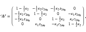
| (A.4) |
 |
(B.2) | ||
 |
(B.3) |
For small retardances, first order terms in ![]() ,
i.e. in
,
i.e. in
![]() ,
dominate the second order terms in
,
dominate the second order terms in ![]() ,
i.e. in
,
i.e. in
![]() .
From the observations, no indications of linear polarizing properties are visible. Hence, all off-diagonal matrix elements proportional to
.
From the observations, no indications of linear polarizing properties are visible. Hence, all off-diagonal matrix elements proportional to
![]() are neglected in the upper left half of the matrix containing the cross talk I
are neglected in the upper left half of the matrix containing the cross talk I
![]() Q. In order to satisfy the properties of a
physical Mueller matrix, i.e.
Q. In order to satisfy the properties of a
physical Mueller matrix, i.e.
![]() ,
,
![]() has to be kept in the lower right part of the matrix. Expressing
has to be kept in the lower right part of the matrix. Expressing ![]() by
by
![]() ,
,
![]() and
and
![]() have to be approximated by
have to be approximated by
![]() ,
leading to:
,
leading to:
![\begin{figure}
\par\includegraphics[width=8.8cm,clip]{2935fig7.eps}
\end{figure}](/articles/aa/full/2005/45/aa2935-05/img133.gif) |
Figure C.1: The coelostat in the equatorial and horizontal coordinate system. The origin is placed in the center of C1. |
The solar position in equatorial coordinates, (
![]() ,
,
![]() ), is taken from an ephemerids table. The location of C2 relative to C1 is given by the angle
), is taken from an ephemerids table. The location of C2 relative to C1 is given by the angle ![]() (cf. Fig. 1,
(cf. Fig. 1, ![]() if C1 is displaced to the east) and the angular height of C2 as seen from C1,
if C1 is displaced to the east) and the angular height of C2 as seen from C1,
![]() .
.
For given values of ![]() and
and
![]() the second
mirror can only have one position to deflect the light into the
telescope proper. Thus,
the second
mirror can only have one position to deflect the light into the
telescope proper. Thus,
![]() can be determined as
follows:
as sketched in Fig. C.1, the
declination of C2 as seen from C1 in equatorial coordinates is
can be determined as
follows:
as sketched in Fig. C.1, the
declination of C2 as seen from C1 in equatorial coordinates is
![]() ,
and the azimuth of C2 in the
horizontal system is
,
and the azimuth of C2 in the
horizontal system is
![]() .
The angular height of C2,
.
The angular height of C2,
![]() ,
is determined by rewriting Eqs. (C.1) and (C.2) into:
,
is determined by rewriting Eqs. (C.1) and (C.2) into:
The rotation angle between the reference frames of the Sun to the first mirror is:
![\begin{figure}
\par\includegraphics[width=8.8cm,clip]{2935fig8.ps}
\end{figure}](/articles/aa/full/2005/45/aa2935-05/img158.gif) |
Figure D.1:
The change of the orientation angle of the linear
polarization,
|
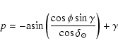
An additional option to test the correct geometry of the telescope
model is the comparison of the physical image rotation, p, due to
the coelostat at
![]() with the rotation of linear
polarization in the model. The analytical calculation for the image
rotation yields an angle
with the rotation of linear
polarization in the model. The analytical calculation for the image
rotation yields an angle
For the linear polarization, the angle
![]() can be calculated for the initial,
can be calculated for the initial,
![]() ,
and final Stokes vector,
,
and final Stokes vector,
![]() .
The difference
.
The difference
![]() must be
identical to p:
must be
identical to p:
![]() is measured with respect to
celestial N-S (first reference frame (RF), fixed on the Sun), but
is measured with respect to
celestial N-S (first reference frame (RF), fixed on the Sun), but
![]() is measured with respect to terrestrial N-S (last
RF, fixed in space). The physical image rotation rotates the celestial
N-S-direction in the focal plane by p away from terrestrial N-S,
thus the angle of the linear polarization in the last RF has to change
by the same amount. Figure D.1 shows the predicted value of p on July 21 with
is measured with respect to terrestrial N-S (last
RF, fixed in space). The physical image rotation rotates the celestial
N-S-direction in the focal plane by p away from terrestrial N-S,
thus the angle of the linear polarization in the last RF has to change
by the same amount. Figure D.1 shows the predicted value of p on July 21 with
![]() and the corresponding value
of
and the corresponding value
of
![]() calculated using the telescope
model. The deviation between both does not exceed the level of
numerical inaccuracies due to the calculation of the inverse of
trigonometric functions in the derivation of the angles of incidence
and rotation angles.
calculated using the telescope
model. The deviation between both does not exceed the level of
numerical inaccuracies due to the calculation of the inverse of
trigonometric functions in the derivation of the angles of incidence
and rotation angles.
Figure E.1 displays the Mueller matrix of the telescope on two
dates: March 21 (
![]() ,
black) and July 28
(
,
black) and July 28
(
![]() ,
grey) for both visible (630
nm, solid) and infrared (1.5
,
grey) for both visible (630
nm, solid) and infrared (1.5 ![]() m, dotted) spectral
ranges. In March the first coelostat mirror, C1, is usually set at
m, dotted) spectral
ranges. In March the first coelostat mirror, C1, is usually set at
![]() in the morning, and -50
in the morning, and -50![]() in the afternoon,
to reduce the pillar height of the second mirror to about 1 m.
in the afternoon,
to reduce the pillar height of the second mirror to about 1 m.
For the visible spectral range the values (n, k) = (1.41, 7.6), for infrared (n, k) = (1.466, 16.118) were used. The cross talk might exceed 20% in the early morning for the visible wavelength, while in the infrared it is usually smaller.
Observations with ![]() = 0
= 0![]() are generally to be preferred
due to the reduction of the cross talk, which is induced by the
coelostat in this configuration. But, depending on the wind speed, it
may be preferable to reduce the image motion by moving the
first coelostat mirror to
are generally to be preferred
due to the reduction of the cross talk, which is induced by the
coelostat in this configuration. But, depending on the wind speed, it
may be preferable to reduce the image motion by moving the
first coelostat mirror to
![]() ,
which reduces the
pillar height of the second mirror.
,
which reduces the
pillar height of the second mirror.
![\begin{figure}
\par\includegraphics[width=16.3cm,clip]{2935fig9.ps}
\end{figure}](/articles/aa/full/2005/45/aa2935-05/img165.gif)