A&A 403, 29-41 (2003)
DOI: 10.1051/0004-6361:20030035
A. Cadez 1 - M. Brajnik 1 - A. Gomboc 1 - M. Calvani 2 - C. Fanton 2
1 - Department of Physics, University of Ljubljana,
Jadranska 19, 6100 Ljubljana, Slovenia
2 -
INAF - Astronomical Observatory of Padova, vicolo
Osservatorio 5, 35122 Padova, Italy
Received 21 October 2002 / Accepted 7 January 2003
Abstract
An efficient numerical code to calculate line profiles
from warped disks around
nonrotating black holes is presented. Extensive numerical experiments suggest a method making it possible
to distinguish between line profiles belonging to flat and warped accretion disks.
The extension of our code to rotating black holes is briefly discussed.
Key words: accretion, accretion disks - black hole physics - galaxies: active
The present analysis focuses mostly on X-ray emission lines coming from the innermost regions of accretion disks, however, the tools we developed can be applied as well to investigate emission lines originating further away from the black hole (optical emission lines, e.g. Calvani et al. 1997; Sulentic et al. 2000).
The plan of the paper is as follows: in Sect. 2 the numerical code to calculate line profiles from warped disks around non-rotating black holes is described. In Sect. 3 we present a collection of theoretical line profiles from warped disks with different parameters and compare them to the closest flat disk profiles. Section 4 is devoted to numerical experiments with warped disk line profiles in order to find a tool to distinguish between line profiles belonging to flat and warped disks. In Sect. 5 we discuss how to extend our results to rotating black holes and we present some preliminary results. Conclusions follow in Sect. 6.
The ray tracing technique for constructing images of accretion disks around black holes and producing their integrated line profiles has been described before in a number of articles (e.g. Fanton et al. 1997; Cadez et al. 1998 and references therein), so they need not be discussed in great detail. We do stress, however, the importance of numerical efficiency, since the multidimensional space of warped and obscured disks requires a large number of sample profiles to be adequately covered.
Our theoretical line profile numerical codes are based on warped
disk models, describing thin,
warped, optically thick disks around non-rotating black holes (for a justification
of warped disks see e.g. Pringle 1996, 1997; Demianski & Ivanov 1997; Quillen 2001; Lubow et al. 2002). The disk surface
is supported by circular time-like geodesic orbits with varying
inclinations to a chosen fixed axis centered to the black hole.
For the shape of the warp we usually use the form proposed by
Hartnoll & Blackman (2000) who parametrize the
twist free disk surface extending
from
![]() (innermost stable circular orbit) to the to
the freely specifiable outer radius
(innermost stable circular orbit) to the to
the freely specifiable outer radius
![]() by two parameters a1 and b in the following way:
by two parameters a1 and b in the following way:
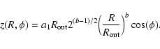 |
(1) |
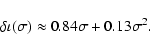
The twisted warp of Hartnoll & Blackman (2000) has
a fixed form, with only the amplitude a2 of the warp as a
parameter:
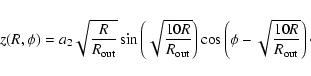 |
(2) |
For the illumination source, following Hartnoll & Blackman
(2000), we use two point sources on the axis of the
disk at the height ![]() ,
where h is a free parameter (in
units of black hole mass; often we use h = 10M), but we also
have the choice to use the simple proper emissivity power law
(
,
where h is a free parameter (in
units of black hole mass; often we use h = 10M), but we also
have the choice to use the simple proper emissivity power law
(
![]() ).
).
To produce an image of the disk we proceed as follows:
 |
(3) |
 |
(5) |
 |
(6) |
 |
(7) |
 |
(8) |
Lightlike geodesics belonging to the second class, which we call
B, reach from infinity and end beyond the horizon of the black
hole. Their angular momentum parameter a is greater than
![]() .
In this case it is convenient to express a in terms
of a parameter
.
In this case it is convenient to express a in terms
of a parameter ![]() :
:
![\begin{figure}
\par\includegraphics[width=13.3cm,clip]{H4037F1.PS}
\end{figure}](/articles/aa/full/2003/19/aah4037/img81.gif) |
Figure 1: The critical geodesics (heavy lines) through Pf divide the orbital plane in three regions. Some geodesics of type Athrough Pf are also shown (gray lines). |
| Open with DEXTER | |
The two critical geodesics (the prograde and the retrograde one)
passing through Pf with
![]() define three
regions denoted by I, II and III. A point Pi laying in
the interior of the circle r=3M - region III - can only be
reached by a geodesic of type B.
If Pi is in the region II, then the most direct geodesic to reach it is type B, which always
remains in region II. However, a point Pi in region IIcan also be reached from Pf by geodesics of type A with the
angular momentum very close to the critical value, so that it
winds about the circle r=3M on the outside before crossing the
boundary I-II. For such a geodesic the true anomaly
define three
regions denoted by I, II and III. A point Pi laying in
the interior of the circle r=3M - region III - can only be
reached by a geodesic of type B.
If Pi is in the region II, then the most direct geodesic to reach it is type B, which always
remains in region II. However, a point Pi in region IIcan also be reached from Pf by geodesics of type A with the
angular momentum very close to the critical value, so that it
winds about the circle r=3M on the outside before crossing the
boundary I-II. For such a geodesic the true anomaly ![]() describes an angle (
describes an angle (
![]() ), where
), where
![]() and Nis the winding number
and Nis the winding number ![]() 1 for boundary crossing geodesics of
type A. If Pi is in the region I, then it can only be
reached by a geodesic of type A with
1 for boundary crossing geodesics of
type A. If Pi is in the region I, then it can only be
reached by a geodesic of type A with ![]()
![]() .
.
After determining the type of the geodesic and the angle
![]() that the true anomaly describes from Pf to Pi, one
chooses the appropriate geodesic equation and expresses the cosine
amplitudinis at both points.
that the true anomaly describes from Pf to Pi, one
chooses the appropriate geodesic equation and expresses the cosine
amplitudinis at both points.
Assume that one wants to find a geodesic of type A that goes
from
![]() to ri. At Pi one obtains:
to ri. At Pi one obtains:
Figure 2 shows a series of images of a mildly warped disk
(a1=0.1, b=3) illuminated by two point sources on the axis at
![]() above the disk plane. The outer radius of the disk is
above the disk plane. The outer radius of the disk is
![]() and the observer is at
and the observer is at
![]() above
the disk plane; images are arranged in order of increasing
above
the disk plane; images are arranged in order of increasing
![]() .
Corresponding Fe K
.
Corresponding Fe K![]() line profiles are also shown
to the right of each image. It is apparent that in this case the
extremities of the line do not change appreciably with
line profiles are also shown
to the right of each image. It is apparent that in this case the
extremities of the line do not change appreciably with ![]() ,
since the innermost region of the disk, which determines the
spread of the line, is never hidden to the observer or shadowed by
the warp. However one notes that the ratio of the blue to red peak
varies considerably even for this moderate warp. By comparing the
pictures and the lines, this is recognized mostly as the
consequence of shadowing either the blue or red part of the
visible image.
,
since the innermost region of the disk, which determines the
spread of the line, is never hidden to the observer or shadowed by
the warp. However one notes that the ratio of the blue to red peak
varies considerably even for this moderate warp. By comparing the
pictures and the lines, this is recognized mostly as the
consequence of shadowing either the blue or red part of the
visible image.
![\begin{figure}
\par\includegraphics[width=17cm]{H4037f2.eps}
\end{figure}](/articles/aa/full/2003/19/aah4037/img101.gif) |
Figure 2:
Images of a mildly warped disk (a1=0.1, b=3,
|
| Open with DEXTER | |
![\begin{figure}
\par\includegraphics[width=15.2cm,clip]{H4037F3.PS}
\end{figure}](/articles/aa/full/2003/19/aah4037/img104.gif) |
Figure 3:
An array of line profiles of a moderately warped disk
(a1=0.1, b=3,
|
| Open with DEXTER | |
A similar array of twisted disk (a2=0.3,
![]() )
line profiles is shown in Fig. 4 together with flat disk
profiles. The blue edge no longer seems to follow the
corresponding Schwarzschild profile. This is easily understood as
now the inner part of the disk is tilted to the disk plane so that
its inclination to the observer depends on the point of view
(
)
line profiles is shown in Fig. 4 together with flat disk
profiles. The blue edge no longer seems to follow the
corresponding Schwarzschild profile. This is easily understood as
now the inner part of the disk is tilted to the disk plane so that
its inclination to the observer depends on the point of view
(![]() )
and is different than that of the average disk plane.
Shadowing again becomes important at high inclinations and its
effects are most pronounced for
)
and is different than that of the average disk plane.
Shadowing again becomes important at high inclinations and its
effects are most pronounced for
![]() ,
,
![]() .
.
![\begin{figure}
\par\includegraphics[width=15cm]{H4037F4.PS}
\end{figure}](/articles/aa/full/2003/19/aah4037/img106.gif) |
Figure 4:
An array of twisted disk (a2=0.3,
|
| Open with DEXTER | |
In analyzing the low signal to noise ASCA data it was standard to
fit Fe K![]() emission lines in the framework of flat accretion
disks with a power law emissivity. However, even with these data
it is often found that one or a number of data channels hold a
value that is considerably different from any model prediction.
Therefore, following Lucy (1974), Mannucci et al. (1992) and Dabrowski et al. (1997), we
proposed a new method for inverting the integral equation
emission lines in the framework of flat accretion
disks with a power law emissivity. However, even with these data
it is often found that one or a number of data channels hold a
value that is considerably different from any model prediction.
Therefore, following Lucy (1974), Mannucci et al. (1992) and Dabrowski et al. (1997), we
proposed a new method for inverting the integral equation
With the better data coming from XMM and Chandra it becomes important to understand how different emission models leave their mark on the emission line profile. To illuminate this question, we study different theoretical line profiles based on flat and warped disk models with different illumination scenarios. We analyze all these lines as if they belong to a flat disk and try to determine from the success of the fit at what level and how is it possible to determine that a given line does not belong to the flat disk model with a smooth emissivity profile.
The basis of the first example is a flat disk of radius 100Mabout a non-rotating black hole, illuminated by two point sources
on the axis at ![]() above and below the disk plane. We
calculate the appropriate theoretical line profile F0(E) for
the inclination
above and below the disk plane. We
calculate the appropriate theoretical line profile F0(E) for
the inclination
![]() and construct noisy lines so
that
and construct noisy lines so
that
![]() ,
where
,
where
![]() is computer generated random noise with the same
intensity in all energy channels and whose rms fluctuations are
denoted by
is computer generated random noise with the same
intensity in all energy channels and whose rms fluctuations are
denoted by ![]() .
When solving Eq. (29), we get a
solution for
.
When solving Eq. (29), we get a
solution for
![]() depending on the input parameters
depending on the input parameters
![]() and
and
![]() and also the
and also the ![]() of the fit
belonging to the difference between the input line profile F(E)and the line profile reconstructed from
of the fit
belonging to the difference between the input line profile F(E)and the line profile reconstructed from
![]() .
We
select
.
We
select
![]() and plot
and plot ![]() as a function of
as a function of ![]() and
and ![]() in Fig. 5.
in Fig. 5.
![\begin{figure}
\par\includegraphics[width=11.5cm,clip]{H4037F5.PS}
\end{figure}](/articles/aa/full/2003/19/aah4037/img113.gif) |
Figure 5:
Fitting the flat disk (at inclination
|
| Open with DEXTER | |
The effect of noise on the line profile, the fit to the line
profile and to the calculated emissivity are shown in
Fig. 6. The left hand side of the figure shows the
original (noise free) profile, the emissivity calculated by
solving Eq. (29) for
![]() and the
fit to the line calculated from the obtained emissivity (on top of
the theoretical line profile). The right hand side of this figure
shows the same quantities for the line profile that was
contaminated by 3% noise.
It is apparent that the noise free line profile reproduces the
emissivity profile of the input model, which in turn reproduces
the line profile quite well. The quality of the fit is only mildly
dependent on numerical parameters, such as the number and
distribution of the radial grid points used in solving
Eq. (29). The slight noise noticeable in the emissivity
profile comes from numerical noise in producing the line profile.
and the
fit to the line calculated from the obtained emissivity (on top of
the theoretical line profile). The right hand side of this figure
shows the same quantities for the line profile that was
contaminated by 3% noise.
It is apparent that the noise free line profile reproduces the
emissivity profile of the input model, which in turn reproduces
the line profile quite well. The quality of the fit is only mildly
dependent on numerical parameters, such as the number and
distribution of the radial grid points used in solving
Eq. (29). The slight noise noticeable in the emissivity
profile comes from numerical noise in producing the line profile.
Note that the emissivity deduced from noisy lines may be quite
different from the original noise free emissivity, however, the
examples shown seem to indicate that a smooth input emissivity
does not generally produce a very jagged output. We understand the
former as a consequence of the fact that Eq. (29) does
not have a unique solution for
![]() ,
since the kernel
,
since the kernel
![]() admits a subspace of solutions
of the homogeneous part of Eq. (29). Additional
conditions may thus be specified to narrow down the solution
space. In our case there is an additional requirement that
admits a subspace of solutions
of the homogeneous part of Eq. (29). Additional
conditions may thus be specified to narrow down the solution
space. In our case there is an additional requirement that
![]() for all r. However, as this is a highly
nonlinear condition, it is not easy to see whether it constrains
the solution completely. In our variational approach to the
solution of Eq. (29) we can apply an additional condition
that the length of the curve
for all r. However, as this is a highly
nonlinear condition, it is not easy to see whether it constrains
the solution completely. In our variational approach to the
solution of Eq. (29) we can apply an additional condition
that the length of the curve
![]() be minimal. This
condition is enforced with a weight parameter
be minimal. This
condition is enforced with a weight parameter ![]() (see Cadez et al. 2000 for details). Our numerical experience shows
that the obtained emissivity profile does not strongly depend on
(see Cadez et al. 2000 for details). Our numerical experience shows
that the obtained emissivity profile does not strongly depend on
![]() as long as it is small (in the appropriate gauge) and
the line results in a smooth emissivity profile. However, in
general, larger
as long as it is small (in the appropriate gauge) and
the line results in a smooth emissivity profile. However, in
general, larger ![]() produces smoother emissivity profiles at
the expense of a worse
produces smoother emissivity profiles at
the expense of a worse ![]() of the fit.
of the fit.
![\begin{figure}
\par\includegraphics[width=17cm,clip]{H4037f6.eps}
\end{figure}](/articles/aa/full/2003/19/aah4037/img120.gif) |
Figure 6: The line profile and the fit (above) and the calculated emissivity profile (below). Left: theoretical line profile, right: line profile contaminated by 3% noise. The right top figure shows one random realization of a noisy line; the error bars properly indicate the noise dispersion. The noise free profile is also indicated in light gray. A number of emissivity profiles obtained for different realizations of noise are shown in the right bottom part of the picture, where the heaviest line corresponds to the above line profile. |
| Open with DEXTER | |
![\begin{figure}
\par\includegraphics[width=12.5cm,clip]{H4037F7.PS}
\end{figure}](/articles/aa/full/2003/19/aah4037/img121.gif) |
Figure 7:
Line profiles of the Fe K |
| Open with DEXTER | |
The most important lesson of this experiment is learned from the
![]() fits in Fig. 5, which were obtained with
fits in Fig. 5, which were obtained with
![]() .
One can see that the width of the
.
One can see that the width of the
![]() minimum grows rapidly with increasing noise amplitude
minimum grows rapidly with increasing noise amplitude ![]() .
In
this numerical experiment (
.
In
this numerical experiment (
![]() )
we obtain the
following relation between the full width of the minimum
)
we obtain the
following relation between the full width of the minimum
![]() (measured in degrees) and
(measured in degrees) and ![]() (in % of max value):
(in % of max value):
![\begin{figure}
\par\includegraphics[width=11.7cm,clip]{H4037F8.PS}
\end{figure}](/articles/aa/full/2003/19/aah4037/img126.gif) |
Figure 8: Line profiles obtained by fitting line profiles shown in Fig. 7 with the flat disk model. |
| Open with DEXTER | |
We suggest that a flat disk fit to an observed line with data
uncertainty ![]() can be considered as successful only if
can be considered as successful only if
![]() and also the width of the
and also the width of the
![]() minimum
is sufficiently narrow; the relationship (30) gives
an approximate measure of this width.
minimum
is sufficiently narrow; the relationship (30) gives
an approximate measure of this width.
In the next numerical experiment we analyze a series of line
profiles belonging to a mildly warped disk with
![]() ,
a1=0.06, b=3, illuminated by two point sources at
,
a1=0.06, b=3, illuminated by two point sources at ![]() .
This disk is observed from an inclination
.
This disk is observed from an inclination
![]() and the angle
and the angle ![]() takes on all values. The resulting line
profiles as a function of
takes on all values. The resulting line
profiles as a function of ![]() are shown in
Fig. 7, the flat disk model fits in
Fig. 8 and the
are shown in
Fig. 7, the flat disk model fits in
Fig. 8 and the ![]() of the fit to these
profiles with the flat disk model are shown in
Fig. 9. Here
of the fit to these
profiles with the flat disk model are shown in
Fig. 9. Here ![]() does not have the usual
meaning, as there was no noise intentionally introduced in the
data, but it was calculated with the assumption that the mean
error of a data point is 10% of the maximum signal value.
does not have the usual
meaning, as there was no noise intentionally introduced in the
data, but it was calculated with the assumption that the mean
error of a data point is 10% of the maximum signal value.
The width of the ![]() minimum is quite narrow, always less
than about
minimum is quite narrow, always less
than about ![]() but its depth depends strongly on the
orientation of the warp. It is deepest (
but its depth depends strongly on the
orientation of the warp. It is deepest (
![]() )
and
narrowest at
)
and
narrowest at
![]() ,
when the warp is seen to bend
perpendicular to the line of sight and most shallow
(
,
when the warp is seen to bend
perpendicular to the line of sight and most shallow
(
![]() )
when the warp is rising toward the observer
)
when the warp is rising toward the observer![]() .
Thus, on the basis of Eq. (30) alone it would be
possible to accept all line profiles from Fig. 7
as belonging to a flat disk, if data noise were about 2%.
However, at this true noise level the actual
.
Thus, on the basis of Eq. (30) alone it would be
possible to accept all line profiles from Fig. 7
as belonging to a flat disk, if data noise were about 2%.
However, at this true noise level the actual ![]() would be
(10/2)2=25 times higher, so that at least three out of four
line fits would have an unacceptable
would be
(10/2)2=25 times higher, so that at least three out of four
line fits would have an unacceptable ![]() .
Repeating the
experiment for
.
Repeating the
experiment for
![]() ,
a1=0.2, b=3,
,
a1=0.2, b=3, ![]() ,
we
find that line profiles belonging to
,
we
find that line profiles belonging to
![]() can not be fitted to a flat disk with acceptable
can not be fitted to a flat disk with acceptable
![]() if the noise level is less than 5%.
if the noise level is less than 5%.
The difference between the good and bad fits also appears striking
if one observes the emissivity profiles obtained by solving
Eq. (29), which are shown in Fig. 10. High
![]() fits generally produce jagged emissivity profiles, while
the good ones return the smooth emissivity, which was
characteristic of the input model.
fits generally produce jagged emissivity profiles, while
the good ones return the smooth emissivity, which was
characteristic of the input model.
On the basis of this experiment we expect that a mildly warped
disk with a1=0.06, b=3, h=10M and
![]() would
be accepted as flat only if the warp would happen to be oriented
more or less perpendicular to the line of sight, i.e. in a sample
of such disks with random orientation of
would
be accepted as flat only if the warp would happen to be oriented
more or less perpendicular to the line of sight, i.e. in a sample
of such disks with random orientation of ![]() ,
the warp would
avoid detection in only one case out of four, if the noise was
less than 2% of the maximum signal.
,
the warp would
avoid detection in only one case out of four, if the noise was
less than 2% of the maximum signal.
![\begin{figure}
\par\includegraphics[width=7.5cm,clip]{H4037F9.PS}
\end{figure}](/articles/aa/full/2003/19/aah4037/img133.gif) |
Figure 9: Flat disk model fits to the line profiles shown in Fig. 7. |
| Open with DEXTER | |
![\begin{figure}
\par\includegraphics[width=13cm,clip]{H4037F10.PS}
\end{figure}](/articles/aa/full/2003/19/aah4037/img134.gif) |
Figure 10: Emissivity profiles derived for the line profiles shown in Fig. 7. |
| Open with DEXTER | |
![\begin{figure}
\par\includegraphics[width=14cm,clip]{H4037F11.PS}
\end{figure}](/articles/aa/full/2003/19/aah4037/img135.gif) |
Figure 11:
The effect of increasing warp on the line profile for a
disk with
|
| Open with DEXTER | |
The effect of increasing the warp is considered in the last
numerical experiment. We again choose a disk with
![]() and b=3,
and b=3,
![]() ,
,
![]() and increase
the warp (a1) in steps of 0.1. The resulting line profiles are
shown in Fig. 11, the flat disk model fits in
Fig. 12, and the
and increase
the warp (a1) in steps of 0.1. The resulting line profiles are
shown in Fig. 11, the flat disk model fits in
Fig. 12, and the ![]() of the fit (assuming
again that
of the fit (assuming
again that ![]() %) with respect to
%) with respect to ![]() and a1 is
shown in Fig. 13. It is clear that the depth of
the
and a1 is
shown in Fig. 13. It is clear that the depth of
the ![]() minimum decreases with increasing warp: for a1>0.1it can be approximated as
minimum decreases with increasing warp: for a1>0.1it can be approximated as
![]() .
Notice, however, that the low
.
Notice, however, that the low ![]() side of the
side of the ![]() surface has "banks" with ridges and valleys reaching as deep as
surface has "banks" with ridges and valleys reaching as deep as
![]() .
Therefore, for warps where the
.
Therefore, for warps where the
![]() minimum is as high as this value, the minimum
has no significance and one should conclude that in this case the
fit of the line to any flat disc model is unsuccessful. For
minimum is as high as this value, the minimum
has no significance and one should conclude that in this case the
fit of the line to any flat disc model is unsuccessful. For
![]() (which is the aspect of the disk that is most similar
to that of a flat disk) this happens at a1=0.35.
(which is the aspect of the disk that is most similar
to that of a flat disk) this happens at a1=0.35.
![\begin{figure}
\par\includegraphics[width=14.8cm,clip]{H4037F12.PS}
\end{figure}](/articles/aa/full/2003/19/aah4037/img139.gif) |
Figure 12: Line profiles obtained by fitting the profiles shown in Fig. 11 with the flat disk model. |
| Open with DEXTER | |
![\begin{figure}
\par\includegraphics[width=10.8cm,clip]{H4037F13.PS}
\end{figure}](/articles/aa/full/2003/19/aah4037/img140.gif) |
Figure 13: Flat disk model fits to the line profiles shown in Fig. 11. |
| Open with DEXTER | |
Figure 14 suggests, as before, that the less successful
fits produce jagged emissivity profiles. If found in real data,
such jaggedness might be interpreted as non plausible.
![\begin{figure}
\par\includegraphics[width=13.2cm,clip]{H4037F14.PS}
\end{figure}](/articles/aa/full/2003/19/aah4037/img141.gif) |
Figure 14: Emissivity profiles derived for the line profiles shown in Fig. 11. |
| Open with DEXTER | |
The message from the above numerical experiments is very simple: the space of functions belonging to flat disk line profiles is very narrow. This means that in the space of all possible line profiles, the measure of the set of those that belong to the flat disk, irrespective of the radial emissivity, is close to zero. Thus, line profiles produced by warped accretion disks can be distinguished from those of the flat ones if noise in data is sufficiently low.
The considerations and results we developed so far are limited to non-rotating black holes. However, at least in interpreting the MCG-6-30-15 X-ray data, a rotating black hole is often invoked (Iwasawa et al. 1996; Sulentic et al. 1998; Guainazzi et al. 1999; Pariev et al. 2001; Wilms et al. 2001; Lee et al. 2002), while evidence for a warped disk may be present in RE J1034+396 (Puchnarewicz & Soria 2002).
The extension of our calculations to warped disks around rotating black holes (Kerr metric) is non trivial for the following reasons: 1) the solutions of geodesic equations cannot (yet?) be written in a form as compact as Eqs. (4) and (12), so that only the map M-1 (and not directly M) can be calculated and 2) shearing due to Lense-Thirring precession shapes the geometric form of the inner disk (Bardeen & Peterson 1975) and determines its rotational law in an essential way. Therefore, a meaningful disk model would have to be derived from a consistent integration of the accretion flow dynamic equations.
Using some simplifying assumptions about the shape and the angular
velocity profile of the warped disk around a Kerr black hole, we
are able to compute the line profiles, some examples of which are
shown in Fig. 15 (Cadez et al. 2002). The
program solves the equations of motion analytically: we decompose
the
![]() components of these equations into a
combination of elliptic and elementary integrals. The program uses
a ray-tracing technique: starting from any point on the
photographic plate (we consider the observer placed above the
equatorial plane) it calculates the constants of
motion of the photon trajectory and then it finds the
intersection of the trajectory with the equatorial plane. Starting
from this point, the program looks for the intersection of the
trajectory with the warped disc; the photon trajectory is then
evaluated upward and downward. If there is an intersection above
the equatorial plane, the program stops the integration: in fact
any other intersection below the equatorial plane corresponds to a
shadowed region of the disc. In general, if there are multiple
intersections between the trajectory and the warped disc, the
program considers the one at highest z-coordinate: the other ones
are associated to points that are not seen from the distant
observer. This procedure is repeated for each trajectory computed
by the program.
components of these equations into a
combination of elliptic and elementary integrals. The program uses
a ray-tracing technique: starting from any point on the
photographic plate (we consider the observer placed above the
equatorial plane) it calculates the constants of
motion of the photon trajectory and then it finds the
intersection of the trajectory with the equatorial plane. Starting
from this point, the program looks for the intersection of the
trajectory with the warped disc; the photon trajectory is then
evaluated upward and downward. If there is an intersection above
the equatorial plane, the program stops the integration: in fact
any other intersection below the equatorial plane corresponds to a
shadowed region of the disc. In general, if there are multiple
intersections between the trajectory and the warped disc, the
program considers the one at highest z-coordinate: the other ones
are associated to points that are not seen from the distant
observer. This procedure is repeated for each trajectory computed
by the program.
As expected, the main difference from the Schwarzschild case is the larger extent of the red wing of the line. However the conclusion that the space of functions belonging to flat disk line profiles is very narrow, will still hold.
![\begin{figure}
\par\includegraphics[width=14cm,clip]{H4037F15.PS}
\end{figure}](/articles/aa/full/2003/19/aah4037/img143.gif) |
Figure 15:
Some examples of line profiles for warped disks around a
rotating (Kerr) black hole with
a/M = 0.009981. All profiles (thick lines) are computed
for
|
| Open with DEXTER | |
The original close form analytic solutions presented in Sect. 2 are very efficient as a tool in applying ray-tracing techniques in the curved space-time of non-rotating black holes. Using this tool we were able to calculate a large number of images and line profiles belonging to theoretical warped accretion disks around non-rotating black holes. The same tool is also found very useful for calculating the kernel of the integral equation which connects the disk emissivity to the line profile, in the framework of the flat accretion disk model, as discussed in Cadez et al. (2000). Using these tools we performed a deep investigation of line profiles from warped disks around non-rotating black holes and compared them to those belonging to flat disks. As a result, we find that: 1) the space of functions belonging to flat disk line profiles is very narrow. This means that in the space of all possible line profiles, the measure of the set of those belonging to the flat disk, irrespective of the radial emissivity, is close to zero. 2) On this basis, we propose a method to distinguish between line profiles that do belong to thin flat disks and those that do not. We expect that this may become a useful tool as soon as better, higher S/N X-ray data will be available.
We also presented some results for warped disks around rotating black holes, and they point to the same general conclusion that lines belonging to flat disks form a very narrow subspace in the space of functions that describe all possible accretion disks.
We point out that a different geometry (such as multiple disk flares, or a disk covering or a patchy corona) could complicate the issue, but we are confident that the above results will still hold.
Acknowledgements
The work of AC and AG was supported by the research grant of the Ministry of Science, Education and Sport of the RS. MC acknowledges the financial support of the Italian MIUR through grant Cofin 00-02-004.

![\begin{displaymath}r(\lambda)=2 M \left[ u_1+{1\over n^2}{1-cn\left(F(\chi _i\ve...
...ft(F(\chi_i\vert m)+\lambda /n\vert m\right)}\right]^{-1}\cdot
\end{displaymath}](/articles/aa/full/2003/19/aah4037/img73.gif)
![\begin{displaymath}n=\bigl [u_1(3 u_1-2)\bigr ]^{-{1\over 4}}
\end{displaymath}](/articles/aa/full/2003/19/aah4037/img76.gif)