The wavefront sensing path consists of a field selector (Spanoudakis et al. 2000) and two wavefront sensors. They are located between the dichroic mirror and the WFS input focus. For the sake of clarity these components are not shown in Fig. 1. The two wavefront sensors, one in the visible and one in the near infrared spectral range, enhance the sky coverage of possible guide stars. The field selector chooses the guide star in a 2 arcmin field of view and allows differential object tracking, pre-calibrated flexure compensation and counter-chopping. In combination with the deformable mirror it is also able to correct for a certain amount of defocus, as needed when the prisms of the atmospheric dispersion compensator are shifted into the beam. Note that this ability of focus correction offers a possibility to perform PD measurements that we will refer to later on (Sect. 3.2).
The high angular resolution camera CONICA is equipped with an Aladdin
array (
![]() )
covering the 1-5
)
covering the 1-5 ![]() m spectral region. Splitting the
wavelength region into two parts (1 to 2.5
m spectral region. Splitting the
wavelength region into two parts (1 to 2.5 ![]() m and 2.0 to
5
m and 2.0 to
5 ![]() m) allows us to keep the light path achromatic. Therefore the
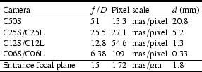
four different pixel scales are realized by seven cameras
(Table 1). To each pixel scale a camera is associated
with the short wavelengths region (S-camera) and another one with the
long wavelengths region (L-camera). The only exception is the camera
with the highest magnification (C50S). There is no long wavelength
counterpart needed
m) allows us to keep the light path achromatic. Therefore the
four different pixel scales are realized by seven cameras
(Table 1). To each pixel scale a camera is associated
with the short wavelengths region (S-camera) and another one with the
long wavelengths region (L-camera). The only exception is the camera
with the highest magnification (C50S). There is no long wavelength
counterpart needed![]() .
.
A variety of different observing modes is provided by the analyzing optics: chronography, low resolution long slit spectroscopy, imaging spectroscopy by a tunable cold Fabry-Perot, polarimetry by wire-grids or Wollaston prisms, and about 40 broad- and narrow-band filters can be chosen.
 |
Copyright ESO 2003
![\begin{figure}
\par\includegraphics[width=8.5cm,clip]{fig/f2914_01.eps} \end{figure}](/articles/aa/full/2003/07/aa2914/img5.gif)