A&A 489, 429-440 (2008)
DOI: 10.1051/0004-6361:200809959
M. J. van Noort1 -
L. H. M. Rouppe van der Voort2,![]()
1 - Institute for Solar Physics of the Royal Swedish Academy of
Sciences, AlbaNova University Center, 106 91 Stockholm, Sweden
2 -
Institute of Theoretical Astrophysics, University of Oslo,
PO Box 1029 Blindern, 0315 Oslo, Norway
Received 13 April 2008 / Accepted 2 June 2008
Abstract
Aims. We aim to achieve both high spatial resolution and high polarimetric sensitivity, using an earth-based 1m-class solar telescope, for the study of magnetic fine structure on the surface of the Sun.
Methods. We use a setup with 3 high-speed, low-noise cameras to construct datasets with interleaved polarimetric states, particularly suitable for Multi-Object Multi-Frame Blind Deconvolution image restorations. We discuss the polarimetric calibration routine and various potential sources of error in the results.
Results. We obtained near diffraction limited images, which have a noise level of ![]()
![]() .
We confirm that dark cores have a weaker magnetic field and a lower inclination angle with respect to the solar surface than the edges of the penumbral filament. We demonstrate that the magnetic field strength in faculae-striations is significantly lower than in other nearby parts of the faculae.
.
We confirm that dark cores have a weaker magnetic field and a lower inclination angle with respect to the solar surface than the edges of the penumbral filament. We demonstrate that the magnetic field strength in faculae-striations is significantly lower than in other nearby parts of the faculae.
Key words: methods: observational - techniques: image processing - techniques: polarimetric - Sun: magnetic fields - sunspots - Sun: faculae, plages
Since the discovery of magnetic features on the Sun (Hale 1908), polarimetry has become an increasingly important diagnostic tool for solar observations. The primary goals in resolution, required signal-to-noise ratio (S/N) and spectral resolution have continually shifted with the objects of interest, from strong, large-scale fields to smaller and often weaker structures.
Considerable efforts have been made toward meeting these requirements.
Examples of modern instruments at some of the
major solar observing facilities are
the Diffraction-Limited Spectro-Polarimeter
(DLSP, Sankarasubramanian et al. 2004),
the Tenerife Infrared Polarimeter (TIP, Collados et al. 2007; Mártinez Pillet et al. 1999),
the Polarimeteric Littrow Spectrograph (POLIS, Beck et al. 2005b),
and the multi-line spectropolarimetric (MTR) observing mode at Themis
(Paletou & Molodij 2001).
Typical spatial resolution achieved with these instruments is of order
0
![]() 5-1
5-1
![]() .
.
Major progress has been made by the spectro-polarimeter
(SP, Lites et al. 2001)
on the Solar Optical Telescope
(SOT, Suematsu et al. 2008)
onboard the Hinode spacecraft.
The combination of ![]() 0
0
![]() 3 spatial resolution and
10-3-10-4 relative sensitivity is defining new standards in
solar polarimetry.
The excellent performance of the image stabilizer of SOT enables the
SP to exploit fully one of the major advantages of space observations:
the absence of seeing.
3 spatial resolution and
10-3-10-4 relative sensitivity is defining new standards in
solar polarimetry.
The excellent performance of the image stabilizer of SOT enables the
SP to exploit fully one of the major advantages of space observations:
the absence of seeing.
Obtaining ground based solar image data suitable for producing sensitive full Stokes maps presents a significant challenge. The problem poses two important requirements on the data, which are difficult to accommodate at the same time. To maximize resolution, as short as possible exposure times are desirable to minimize smearing by seeing-induced image motions. To maximize sensitivity, as long as possible exposure times are needed to minimize the photon noise in the images. Obviously these two requirements are mutually exclusive so that a suitable compromise must be made.
Several approaches currently exist toward addressing one or both of these problems, two of which have been used extensively. The first approach has been very successful at eliminating artificial signals from seeing-induced image motions, by means of high-frequency modulation of the polarimetric state, and integration in all polarimetric states for a long time. As the seeing-induced image aberrations are identical for all intents and purposes, artifacts resulting from image-motions are essentially eliminated. Using this method, a relative sensitivity of 10-5 was achieved by the Zürich Imaging Stokes Polarimeter II (ZIMPOL, Gandorfer & Povel 1997). Such extreme levels of sensitivity can currently only be achieved at the cost of losing a great deal of spatial resolution.
Another approach is the removal of seeing-induced image aberrations by numerical means. This approach attempts to address both problems at once, but requires frequent CCD readouts to construct an image stack for analysis. Consequently, it is of particular importance to ensure that the photon noise exceeds the readout noise of the CCD, to achieve a good S/N in the end.
Bello González & Kneer (2008) achieved a
polarimetric sensitivity of 10-3at a spatial resolution of ![]() 0
0
![]() 3 using a combination of
adaptive optics and speckle reconstruction.
Their observing method elaborates on the pioneering work of
Keller & von der Lühe (1992) at the Swedish Vacuum Solar Telescope,
where they introduced the use of a narrow-band channel in combination
with a wide-band channel. The high light levels in the wide-band
channel enabled them to successfully perform speckle restorations,
after which the seeing information acquired from the wideband
restorations was used to restore the narrowband images.
3 using a combination of
adaptive optics and speckle reconstruction.
Their observing method elaborates on the pioneering work of
Keller & von der Lühe (1992) at the Swedish Vacuum Solar Telescope,
where they introduced the use of a narrow-band channel in combination
with a wide-band channel. The high light levels in the wide-band
channel enabled them to successfully perform speckle restorations,
after which the seeing information acquired from the wideband
restorations was used to restore the narrowband images.
The Multi-Object Multi-Frame Blind Deconvolution (MOMFBD) post-processing method used by van Noort et al. (2005), like the speckle method used by Keller & von der Lühe (1992), combines the signal accumulated in a large number of short-exposure images using an image restoration process that separates the image information from the seeing-induced image blurring and distortions.
Although more expensive numerically than speckle reconstruction, some advantages of the MOMFBD method are that: some fixed (instrumental) aberrations can be corrected using a phase-diversity channel; the process uses all image channels for wavefront sensing, resulting in a more accurate separation of image information and seeing distortions; and the requirements for the image data are less stringent in terms of the statistical independence of individual exposures and the seeing statistics in general, so that it can be easily applied to very high cadence data, recorded using an adaptive optics system.
To acquire accurate polarimetric data, a reliable polarimeter is needed. Although the entire telescope is part of the polarimeter, it is more practical to separate the vacuum part of the telescope from the remainder of the optical setup and model it separately.
The reason for this is that the design of the
Swedish 1 m Solar Telescope (SST, Scharmer et al. 2003a)
includes vacuum windows and
large angle of incidence mirrors, so that the instrumental
polarization is not only considerable, at ![]() 10% in both Stokes
Q and U and around 2% in Stokes V, it also depends on the mirror
angles and thus on the observing position in the sky and is therefore
time dependent.
10% in both Stokes
Q and U and around 2% in Stokes V, it also depends on the mirror
angles and thus on the observing position in the sky and is therefore
time dependent.
Since the determination of the telescope matrix for all possible positions in the sky is not practically achievable (although not impossible), it makes sense to model the telescope and calibrate the model parameters instead. For this, however, an accurate polarimeter is required.
The choice of LCVRs over the more commonly used Ferro-Electric LCs,
is motivated by the greater flexibility in choosing the modulation
scheme and effortless adaptation to changes in the observing
wavelength. The price to pay for this flexibility is a ``slow'' response to changes
in modulation value (![]() 10 ms or more) when an increase in
retardance is required, which presents a problem when combined with
high-speed cameras, as well as stringent stability requirements on the
driving voltage, especially at the high end of the retardance range of
the LCVRs, where the sensitivity to voltage changes is largest.
10 ms or more) when an increase in
retardance is required, which presents a problem when combined with
high-speed cameras, as well as stringent stability requirements on the
driving voltage, especially at the high end of the retardance range of
the LCVRs, where the sensitivity to voltage changes is largest.
The speed restrictions of the LCVRs can be effectively dealt with using an ``overdrive'' approach: when an increase in retardance is needed, the driving voltage amplitude is set to 0, to maximize the rate of change. When the desired retardance value is reached (or passed), the voltage appropriate to the target retardance value is applied, upon which the LCVR has only a small, negative, retardance change to cover, which can be accomplished more than an order of magnitude faster than for an equal positive change. In combination with optimizing the state order of the modulation scheme, the tuning time of the LCVRs can be kept below 10 ms at all times, a requirement imposed by the readout time of the cameras used.
Since the retardance value of Liquid Crystals is also temperature sensitive, the ability to continuously vary the retardance value is an advantage: it can be used to correct the retardance based on the measured temperature, so that complications related to thermal stabilization can be avoided.
The current implementation, however, still makes use of a simple thermal stabilization circuit, which, although it improves considerably upon the unstabilized situation, is not able to cope with sudden changes in the environmental conditions, such as those arising from changes in ventilation. Therefore, although the polarimeter is currently operational, its properties are slowly varying over time and need to be recalibrated as frequently as possible. Once the stability issues are properly addressed, this should not be needed, as long as the optical setup remains the same.
For most of the data presented here, the polarimeter could be calibrated within a few hours of taking the data, but uncorrected variations in the measured Stokes parameters at the level of approximately one percent usually remain.
 |
(1) |
For calibration purposes, the LP was positioned at 0![]() ,
45
,
45![]() ,
90
,
90![]() ,
and 135
,
and 135![]() ,
coinciding with the Q, U, -Q, and -Uaxes respectively. This ensures that all Stokes components are present at their
maximum amplitudes and with opposite sign, to reduce
sensitivity to offsets and other sources of contamination in the
calibration data. Although a condition number analysis of the problem
by Selbing (2005) suggests that angle steps of 30
,
coinciding with the Q, U, -Q, and -Uaxes respectively. This ensures that all Stokes components are present at their
maximum amplitudes and with opposite sign, to reduce
sensitivity to offsets and other sources of contamination in the
calibration data. Although a condition number analysis of the problem
by Selbing (2005) suggests that angle steps of 30![]() over a
range of only 180
over a
range of only 180![]() should be sufficiently accurate to determine fully the
problem, the angles for the retarder were taken to be every 5
should be sufficiently accurate to determine fully the
problem, the angles for the retarder were taken to be every 5![]() from 0
from 0![]() to 365
to 365![]() ,
a total of 74 angles, to average
out any error in the QWP angles and photon noise in the data that may
exist.
,
a total of 74 angles, to average
out any error in the QWP angles and photon noise in the data that may
exist.
Strictly speaking, the modulation matrix elements can now be fitted by a simple matrix inversion. However, this would assume that the retardance value and offset angle of the QWP are known perfectly, as well as that the intensity was constant during the recording of the calibration data. An iterative approach is the most obvious way forward because the expressions containing the retarder parameters are non-linear and, to compensate for the varying intensity, the observations must be normalized to I, for which the inverse of the modulation matrix itself needs to be known.
Using a downhill gradient-search algorithm for all parameters is the simplest
way to find the solution, but it is rather slow and can benefit
greatly from step direction optimization methods such as
conjugate-gradient optimization. Unfortunately, it is easy to end up in a local
minimum close to the global minimum. An improvement can be made by using
as much of the explicit solution as possible (M) and using a downhill
search algorithm for the remaining parameters (![]() and
and
![]() ).
Although this method
converges far more rapidly and is less likely to find a local minimum, it
is more likely to end up with a completely wrong solution if the start
solution is far away from the real solution. However, both methods are
based on minimizing the same error function and converge toward the
same solution, if sufficiently restrictive convergence criteria are
used.
).
Although this method
converges far more rapidly and is less likely to find a local minimum, it
is more likely to end up with a completely wrong solution if the start
solution is far away from the real solution. However, both methods are
based on minimizing the same error function and converge toward the
same solution, if sufficiently restrictive convergence criteria are
used.
![\begin{figure}
\par\includegraphics[width=9cm,clip]{9959f01.eps}\end{figure}](/articles/aa/full/2008/37/aa09959-08/img24.gif) |
Figure 1:
Polarimetry Calibration for 13-Sep.-2007. The lines are
theoretical curves fitted to the data recorded for the polarimetric
states. The horizontal dotted lines are the LP-only observations,
the vertical dashed lines are the fitted angle offset (for 0 |
| Open with DEXTER | |
In addition to the calibration data, observations were made without the QWP. This provides an independent way of checking the quality of the fit, since the fitted data curves should assume the value of the LP-only observations at the retarder angle equal to that of the LP.
Figure 1 shows an example of a calibration data
set with fitted model curves, for the mean over the field of
view. Typically, a total of 8 of these curves are used to fit the
modulation matrix elements. The QWP angle for which the curves assume
the value of the LP-only observations is the same for all curves to
within ![]() ,
but differs from the calibrated QWP offset angle
by
,
but differs from the calibrated QWP offset angle
by
![]() ,
possibly due to inaccuracies introduced by the
manual positioning of the LP, the positions of which were not included
in the fit.
,
possibly due to inaccuracies introduced by the
manual positioning of the LP, the positions of which were not included
in the fit.
From the modulation matrix produced by the calibration, efficiencies of 0.56, 0.53, and 0.51 for Stokes Q, U, and Vrespectively can be derived. The total efficiency of 0.94 indicates that the modulation scheme is close to the theoretical optimum.
Since the telescope uses 2 mirrors at a 45![]() angle of incidence and
a vacuum-window, it is strongly polarizing and the polarization
depends on the pointing direction. To predict the Mueller
matrix of this system for arbitrary azimuth and elevation angles, it needs to
be modeled and then calibrated. The model is based on the method used by
Skumanich et al. (1997), a method that was applied successfully to model
the DST, the SVST (LPSP, Sanchez Almeida et al. 1997; Mártinez Pillet et al. 1999), and
the German VTT (Beck et al. 2005a).
Selbing (2005) adapted the method to describe the SST optics.
angle of incidence and
a vacuum-window, it is strongly polarizing and the polarization
depends on the pointing direction. To predict the Mueller
matrix of this system for arbitrary azimuth and elevation angles, it needs to
be modeled and then calibrated. The model is based on the method used by
Skumanich et al. (1997), a method that was applied successfully to model
the DST, the SVST (LPSP, Sanchez Almeida et al. 1997; Mártinez Pillet et al. 1999), and
the German VTT (Beck et al. 2005a).
Selbing (2005) adapted the method to describe the SST optics.
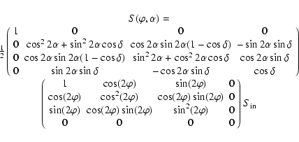
The Mueller matrix of the telescope is the product of the
series of Mueller matrices for each of the optical components the
light passes through before exiting the bottom of the telescope
 |
(2) |
The corresponding matrix is obviously position dependent, but this is through the rotation matrices R only, so that this dependence is known once the matrices for all other components are known. The mirror matrices can be described using a general expression with only 2 unknown parameters, so that only L and a few parameters need to be calibrated. This can only be done by fitting the predicted telescope response to known input Stokes data.
Unfortunately, since the entrance window has a 1 m diameter, it is not possible to use the method of generating Stokes vectors used when calibrating the polarimeter, since a 1 m retarder of sufficient quality is hard to obtain. Only a fit to linearly polarized light is possible.
To provide a source of linearly polarized light, a large sheet of polarizing material was mounted on a rotating wheel in front of the telescope main lens. This wheel was then rotated slowly and continuously while pointing toward the Sun, thus presenting the telescope with all Stokes parameters apart from Stokes V. Polarimetric data were acquired continuously throughout the day, to provide information on the azimuth and elevation dependence of the telescope matrix.
Although of fundamental importance to the accuracy of the Stokes data presented here, further details of the telescope calibration procedure are beyond the scope of this paper and are outlined in detail by Selbing (2005). We limit ourselves to stating that the estimated error in the predicted output of the telescope was found to be below 0.5% in Stokes Q, U, and V, based on the only calibration performed so far, in March 2004. However, since there is no information available about the effects of aging and maintenance on the model parameters, this estimate may no longer be accurate.
Figure 2 shows the instrumental polarization estimated from a full day of full Stokes data recorded on 12 Sep. 2006, more than a year after the telescope model was calibrated. Since the FOV is dominated by a large sunspot close to the center of the solar disc, the derived offset for each Stokes parameter may contain a non-instrumental component of solar origin. Although the model predictions show a small systematic difference from the data, in particular the extreme values of Q and U appear to be assumed at a somewhat different time of day from the model, the agreement with the telescope model appears to be closer than approximately 1% of I, which is not significantly poorer than found 18 months earlier.
![\begin{figure}
\par\includegraphics[width=9cm,clip]{9959f02.eps}\end{figure}](/articles/aa/full/2008/37/aa09959-08/img32.gif) |
Figure 2: Instrumental polarization for 12-Sep.-2006 as a function of time. The plotted curves are the model predicted telescope polarization for Q (solid), U (dotted) and V (dashed), the crosses are the actual values measured below the exit window of the telescope. |
| Open with DEXTER | |
From several campaigns during the 2006 observing season, we selected 4 data sets of sunspots that were taken under excellent seeing conditions. Detailed information about the different targets is presented in Table 1. Figure 3 shows the four Stokes maps for Fe I 630.25 nm -5 pm for one of the selected sunspots.
![\begin{figure}
\par\includegraphics[width=18cm,clip]{9959f03.eps}\end{figure}](/articles/aa/full/2008/37/aa09959-08/img33.gif) |
Figure 3:
Sunspot AR10908 observed on 12 Sep. 2006 in
Fe I 630.25 nm -5 pm. The color scaling saturates at
|
| Open with DEXTER | |
The quality of the data benefitted from the SST adaptive optics system (AO, Scharmer et al. 2003b) and post-processing using the Multi-Object Multi-Frame Blind Deconvolution (MOMFBD, van Noort et al. 2005) image restoration method. The use of MOMFBD is complementary to the use of AO in the sense that it provides the possibility to simultaneously achieve high image quality close to and at large angular distances away from the AO wavefront sensor.
Narrow band images in the wings of the Fe I 630.25 nm line were
obtained with the Solar Optical Universal Polarimeter
(SOUP, Title & Rosenberg 1981), which has a FWHM of 7.2 pm.
Three science cameras were employed with
![]() pixel CCD
chips (pixel scale 0
pixel CCD
chips (pixel scale 0
![]() 063, the diffraction limit
063, the diffraction limit ![]() D of
the SST at 630 nm is 0
D of
the SST at 630 nm is 0
![]() 13).
One of these cameras was positioned behind the SOUP filter and the other
two were set-up as a phase-diversity pair that received 7.5% of the
light on a branch split off the main beam before the SOUP
but after the SOUP pre-filter (0.8 nm passband centered on
630.25 nm).
The exposures of all three cameras were synchronized by means of an
optical chopper.
The optical setup was similar to the one described in
De Pontieu et al. (2007) with an additional pair of
LCVRs positioned between the collimator and re-imaging lens, and is
illustrated in Fig. 4.
13).
One of these cameras was positioned behind the SOUP filter and the other
two were set-up as a phase-diversity pair that received 7.5% of the
light on a branch split off the main beam before the SOUP
but after the SOUP pre-filter (0.8 nm passband centered on
630.25 nm).
The exposures of all three cameras were synchronized by means of an
optical chopper.
The optical setup was similar to the one described in
De Pontieu et al. (2007) with an additional pair of
LCVRs positioned between the collimator and re-imaging lens, and is
illustrated in Fig. 4.
Since the polarimetric signals of interest are usually weak, it is of
crucial importance to obtain the largest S/N ratio possible. Although
the Sun is an excellent source of photons, when reducing the spectral
range to only a few tens of pm, acquiring a detectable quantity of
photo electrons in the few ms permitted by the seeing
becomes a challenge.
To take full advantage of the available light, the cameras used at the
SST are Sarnoff 1M100 cameras, the CCD of which
has a quantum efficiency of 0.7 at 630 nm and consists of 16
separate segments that can be read out in parallel.
By using a slow
pixel clock, the result is a camera with exceptionally low readout
noise and a readout time of only 10 ms.
Even with this short readout time, the most effective exposure time is a
compromise between as short as possible, to ``freeze'' the seeing, and
at least longer than the readout time, to achieve a reasonable efficiency.
In practice, the rotation rate was set to be approximately 36 Hz, giving an exposure
time of ![]() 17 ms and a duty-cycle of approximately 60%.
Apart from the desire to have a large duty-cycle, a shorter
exposure at the current light levels (using the SOUP filter which has
a transmission of only
17 ms and a duty-cycle of approximately 60%.
Apart from the desire to have a large duty-cycle, a shorter
exposure at the current light levels (using the SOUP filter which has
a transmission of only ![]() 15%)
would result in a photon noise that is at or below the readout noise
of the camera, a situation that the MOMFBD reduction is currently
unable to handle.
15%)
would result in a photon noise that is at or below the readout noise
of the camera, a situation that the MOMFBD reduction is currently
unable to handle.
The LCVRs of the polarimeter cycled through a sequence of 4 states,
changing state for each exposure during the read-out time of the cameras.
The SOUP filter ran a program switching between the red and
blue wing of the Fe I 630.25 nm line, at ![]() pm offset from
the line core.
A change of line position was made every
pm offset from
the line core.
A change of line position was made every ![]() 14 s, a period covering typically
125 LCVR cycles.
With a line position changing time of about 7 s, the acquisition of a
full data set, containing two line positions and all LCVR cycles, was completed
in about 35 s.
The exact number of images (and effective exposure time) for each data
set is specified in Table 1.
14 s, a period covering typically
125 LCVR cycles.
With a line position changing time of about 7 s, the acquisition of a
full data set, containing two line positions and all LCVR cycles, was completed
in about 35 s.
The exact number of images (and effective exposure time) for each data
set is specified in Table 1.
Figure 5 illustrates the acquisition scheme of
the data. Since the cameras are synchronized, 3 exposures share the
same wavefront realization t (x-axis): one SOUP image with a
specific line position and LCVR state o (z-axis), and two wide-band images with
known diversity k (y-axis), one in focus and one slightly out of focus
(![]() 12 mm on a 45 m focal length).
12 mm on a 45 m focal length).
The figure is similar to Fig. 7 in van Noort et al. (2005) with the important difference that the LCVR states are now changed for each exposure instead of following a burst of several exposures. This produces a collection of polarimetric states that is more homogeneous in terms of seeing aberrations, so that the level of seeing cross-talk is already reduced significantly prior to MOMFBD processing. The interleaved character of the data set is akin to the high speed modulation used by the Zürich Imaging Polarimeter (ZIMPOL, Gandorfer & Povel 1997), which employs modulation in the kHz range and is highly beneficial for the construction of high-sensitivity Stokes maps.
The images from the wide-band cameras vary only because of seeing variations, while images from the SOUP camera vary constantly due to seeing variations, the modulation of the LCVRs, and the changing line position. Since the wavelength of the wide-band images is almost identical to that of the narrowband images, the wide-band images can be used as an ``anchor'' channel, to which all restored SOUP objects are aligned in the MOMFBD restoration procedure as discussed at length in van Noort et al. (2005).
To calibrate the inter-camera alignment, images of an array of
30 ![]() m pinholes were recorded. By fitting these pinhole images to each other and
assuming that they are the same, the relative offset of each camera pixel
with respect to a properly chosen reference camera can be calculated using the
MOMFBD code in calibration mode. These image offset calibrations result in the
alignment of restored objects with a typical accuracy of
m pinholes were recorded. By fitting these pinhole images to each other and
assuming that they are the same, the relative offset of each camera pixel
with respect to a properly chosen reference camera can be calculated using the
MOMFBD code in calibration mode. These image offset calibrations result in the
alignment of restored objects with a typical accuracy of ![]() 0.05 pixels.
This means that the restored SOUP objects have
near-perfect alignment - even though the individual exposures are not
recorded simultaneously - and no further alignment by means of
cross-correlation is needed to construct the Stokes maps.
The level of false signals induced by seeing is therefore generally
very low (see also Sect. 4.1).
0.05 pixels.
This means that the restored SOUP objects have
near-perfect alignment - even though the individual exposures are not
recorded simultaneously - and no further alignment by means of
cross-correlation is needed to construct the Stokes maps.
The level of false signals induced by seeing is therefore generally
very low (see also Sect. 4.1).
| |
Figure 4: Schematic drawing of the optical set-up. |
| Open with DEXTER | |
![\begin{figure}
\par\includegraphics[width=9cm,clip]{9959f05.eps}\end{figure}](/articles/aa/full/2008/37/aa09959-08/img39.gif) |
Figure 5:
Sketch of the acquisition scheme of a full Stokes MOMFBD data
set for 2 line positions. The 2 line positions,
|
| Open with DEXTER | |
Table 1:
Summary of observed targets.
![]() with
with
![]() the observing angle. e time is the effective exposure
time per line position, i.e., the sum of all exposure times.
the observing angle. e time is the effective exposure
time per line position, i.e., the sum of all exposure times.
Unless otherwise stated, all images were reduced using
![]() (
(![]()
![]() )
and seamless mosaicking of the tapered subimages. The
reductions were done on a 90 CPU 3.2 GHz Intel Xeon cluster at the
University of Oslo using 34 Karhunen-Loéve wavefront modes and
converged until the relative change in the wavefront coefficients was
<10-4.
)
and seamless mosaicking of the tapered subimages. The
reductions were done on a 90 CPU 3.2 GHz Intel Xeon cluster at the
University of Oslo using 34 Karhunen-Loéve wavefront modes and
converged until the relative change in the wavefront coefficients was
<10-4.
One of the main motivations for conducting observations in the way that we describe in this paper is the detection of weak polarization signals. It is therefore important to quantify accurately the noise level in the data. The main source of noise is photon noise. Read-out noise is a minor source of noise: for the Sarnoff cameras, the read-out noise is specified by the manufacturer to be on the order of 25 electrons, which amounts to 1-2 counts. Seeing cross-talk is another potential source of noise. As discussed in Sect. 3, the use of a wide-band anchor channel in MOMFBD restorations reduces seeing cross-talk significantly in derived quantities such as magnetograms. The use of interleaved LCVR state exposures, in addition, reduces yet more the effect of seeing cross-talk.
Even though, images free from polarization signal are needed to investigate the noise, there is no location on the Sun that is guaranteed to be completely free of magnetic field. Moreover, observing at a presumably field-free location or at a magnetically insensitive wavelength does not provide polarization-free images due to the instrumental polarization cross-talk. Although the latter can be corrected for using the telescope model, this potentially entangles the polarization cross-talk with the seeing cross-talk, which is undesirable.
Instead, we opted for ``re-labeling'' the data recorded for one specific modulation state and wavelength to the other states and reducing this dataset as if it were polarized data. Since the signal in all images corresponds to the same state, no polarization signal should be detected after the reductions are complete. By repeating this for all states, a reasonable estimate can be made of the false signal due to for example noise and seeing-crosstalk. Unfortunately, since the polarimeter itself polarizes in Stokes Q and U, but not much in V, this method could only be used on data that contain only Stokes V observations.
The top panels of Fig. 6 show parts of these
``fake'' magnetograms constructed using the standard formula
![]() ,
where
,
where
![]() and
and
![]() are from the same state. Panel (a) is constructed from flat-fielded
images, panel (b) is based on MOMFBD restored data. Since the FOV
shown in these panels is off-center (away from the AO wavefront sensor
target area), anisoplanatism can be expected to introduce image shifts
and deformations that introduce seeing crosstalk. For the
flat-fielded data we observe patterns on granular scales that can be
attributed to seeing crosstalk. For the MOMFBD data, these patterns
cannot be discerned. This is confirmed by a power spectrum analysis that
shows no conspicuous bumps indicating a significant level of false
signal due to seeing crosstalk.
are from the same state. Panel (a) is constructed from flat-fielded
images, panel (b) is based on MOMFBD restored data. Since the FOV
shown in these panels is off-center (away from the AO wavefront sensor
target area), anisoplanatism can be expected to introduce image shifts
and deformations that introduce seeing crosstalk. For the
flat-fielded data we observe patterns on granular scales that can be
attributed to seeing crosstalk. For the MOMFBD data, these patterns
cannot be discerned. This is confirmed by a power spectrum analysis that
shows no conspicuous bumps indicating a significant level of false
signal due to seeing crosstalk.
![\begin{figure}
\par\includegraphics[width=9cm]{9959f06.eps}\end{figure}](/articles/aa/full/2008/37/aa09959-08/img47.gif) |
Figure 6: Panel a) shows a magnetogram-like image constructed from flatfielded images of the same liquid crystal state. Panel b) shows a similar image constructed from a MOMFBD restoration based on the same images as panel a). Both panel a) and b) have the same scaling, -0.01 to +0.01. Panel c) shows the Fe I 630.2 -5 pm Stokes V magnetogram from the same data set and the same number of images. The scaling is -0.05 to +0.05. Panel d) shows the wide band image of the same region and data set. |
| Open with DEXTER | |
The noise pattern in panel (a) and (b) is different: the ``orange-peel'' pattern for the MOMFBD data has a larger characteristic scale than for the flat-fielded data, which varies on a pixel-to-pixel scale. The characteristic ``orange-peel'' pattern in the MOMFBD data can be explained by the low-pass filter employed during the restoration: power at the highest frequencies, beyond the diffraction limit and the noise-dominated regime in Fourier space, are attenuated. This leaves a background or noise pattern with a characteristic spatial scale of a few pixels. The noise filter is a fundamental part of the deconvolution conducted in the MOMFBD procedure. It suppresses the noise level slightly below the level expected from photon noise (see below). However, the characteristic noise pattern with a scale close to the diffraction limit poses problems for the detection of small-scale and weak-signal features because it is difficult to unambiguously distinguish noise at that scale from weak signal. In such cases, a time sequence of measurements could validate detection of weak features, provided that they survive sufficiently long.
Uncertainties in the knowledge of the varying photo sensitivity of the detector pixels is another potential source of error. This type of noise is also known as gain table or flat-field noise. The same detector is used for recording all polarization states but the flatfield for each state is found to be different and therefore uncertainty in the flatfield introduces noise. For our observations, flatfields were constructed by adding a large number of exposures, while the telescope is sweeping over the solar disk. Due to the rapid motion and addition of a large number of images, solar features are effectively averaged out. We found that by adding more than 1000 images, the uncertainty in the flatfield decreases to below 10-3, the level below which this kind of noise becomes negligible.
Figure 7 shows the RMS noise level of several
restored data sets as a function of the number of frames per state,
for images ``restored'' using flat-fielding and addition only and for
images restored using MOMFBD reduction. The flat-fielded data follows
the expected 1/![]() behavior well, which confirms that the
exposures are dominated by photon noise. The noise level of the MOMFBD
restored images is lower than the theoretical 1/
behavior well, which confirms that the
exposures are dominated by photon noise. The noise level of the MOMFBD
restored images is lower than the theoretical 1/![]() limit, presumably due to a reduction in high-frequency noise from
filtering beyond the diffraction limit.
limit, presumably due to a reduction in high-frequency noise from
filtering beyond the diffraction limit.
A number of noise measurements of real Stokes magnetograms are plotted in Fig. 7. These measurements were carried out on small, presumably field-free regions in the FOV. The noise in full Stokes measurements is about two times higher than in observations devised to measure only Stokes V. This is because the efficiency in measuring the 4 Stokes parameters is almost four times lower than measuring only Stokes V.
For a full Stokes measurement, 125 exposures per state, or
500 exposures in total, is about the maximum number of exposures that
can be included if one considers the photospheric evolution time. It
takes about 14 s to acquire these 500 exposures. A disturbance moving
at a velocity of the photospheric sound speed (![]() 7 km s-1) travels
about 100 km during that time, which is about the distance of the
diffraction limit at this wavelength.
7 km s-1) travels
about 100 km during that time, which is about the distance of the
diffraction limit at this wavelength.
Following the same arguments for a measurement of only Stokes V,
double the amount of exposures per state can be used since the liquid
crystals alternate between two states only. In the Stokes V only data
set presented in Fig. 7, we measure a noise level of
about
![]() in Fe I 630.2 -5 pm. Using the
calibration constant of 16551 Mx cm-2 per polarization percent
found by Berger et al. (2004) for Fe I 630.2 -5 pm SOUP
Stokes V magnetograms, this noise level is equivalent to a magnetic
flux density of 33 Mx cm-2.
in Fe I 630.2 -5 pm. Using the
calibration constant of 16551 Mx cm-2 per polarization percent
found by Berger et al. (2004) for Fe I 630.2 -5 pm SOUP
Stokes V magnetograms, this noise level is equivalent to a magnetic
flux density of 33 Mx cm-2.
![\begin{figure}
\par\includegraphics[width=9cm]{9959f07.eps}\end{figure}](/articles/aa/full/2008/37/aa09959-08/img49.gif) |
Figure 7:
Noise in ``fake'' magnetograms as function of number of
exposures per state. The solid line is for flatfielded data, similar
to panel a) of Fig. 6. Crosses are MOMFBD
restored data, similar to panel b) of Fig. 6. The
dotted line is the 1/ |
| Open with DEXTER | |
To establish the achieved spatial resolution of the observations, we complete a power spectrum analysis and a close inspection of the smallest resolved structures in the data.
Figure 8 shows sample images of the observations from 12 Sep. 2006. The images shown are based on 110 exposures per state, corresponding to a total of 440 exposures. The data for panel (c) was flat-fielded and added, as if it were obtained using long exposures (1.65 s per state, 6.6 s effective exposure in total), but with the added advantage that the states were interleaved and therefore the seeing for each of the states was more equal than for equivalent long exposures. The difference in resolution between panel (b) and (c) is striking. The MOMFBD restored Stokes V image shows a lot more fine detail and there are many examples of small, weak features that are not resolved in the flat-fielded stokes V image.
The power spectra in panel (d) are angular averages of 2D Fourier
power spectra of a
![]() pixel sub-area in a corner of the
FOV, away from the sunspot and showing only granulation.
The power spectrum of the MOMFBD restored wide-band image (based on
440 focus and 440 de-focus images) shows a gradual decrease in power
to higher frequencies, with a steeper decline between about 0
pixel sub-area in a corner of the
FOV, away from the sunspot and showing only granulation.
The power spectrum of the MOMFBD restored wide-band image (based on
440 focus and 440 de-focus images) shows a gradual decrease in power
to higher frequencies, with a steeper decline between about 0
![]() 18
and just above the diffraction limit
18
and just above the diffraction limit ![]() /D at 0
/D at 0
![]() 134. The
steep decline is an effect of the noise filter that has a smooth
transition from no effect at the lower frequencies to full
suppression at the highest, noise-dominated, frequencies.
The SOUP exposures used to construct the Stokes data are
noisier than the wide-band images and therefore the noise filter sets
in at a lower frequency, corresponding to a spatial scale of about
0
134. The
steep decline is an effect of the noise filter that has a smooth
transition from no effect at the lower frequencies to full
suppression at the highest, noise-dominated, frequencies.
The SOUP exposures used to construct the Stokes data are
noisier than the wide-band images and therefore the noise filter sets
in at a lower frequency, corresponding to a spatial scale of about
0
![]() 2.
The power spectrum for the flat-fielded Stokes I image is shown for
comparison and illustrates how the MOMFBD restoration enhances
power at all relevant spatial frequencies.
There is a small enhancement in power just above the diffraction limit
for the flat-fielded data. That is caused by a small localized power
enhancement in the Fourier domain, probably due to some
internal camera property.
This has no significant effect on the restored data since it is
effectively suppressed by the noise filter.
2.
The power spectrum for the flat-fielded Stokes I image is shown for
comparison and illustrates how the MOMFBD restoration enhances
power at all relevant spatial frequencies.
There is a small enhancement in power just above the diffraction limit
for the flat-fielded data. That is caused by a small localized power
enhancement in the Fourier domain, probably due to some
internal camera property.
This has no significant effect on the restored data since it is
effectively suppressed by the noise filter.
It is difficult to extract a hard number for the achieved spatial
resolution from the averaged power spectrum. Even though the steep
decline due to the noise filter starts slightly above 0
![]() 2, a
claim of a spatial resolution of less than 0
2, a
claim of a spatial resolution of less than 0
![]() 2 in the Stokes
data is justified. We performed a close inspection of the
smallest features in the Stokes magnetograms and found many examples
of structures that had widths with a FWHM of about 3 pixels
(0
2 in the Stokes
data is justified. We performed a close inspection of the
smallest features in the Stokes magnetograms and found many examples
of structures that had widths with a FWHM of about 3 pixels
(0
![]() 19).
19).
![\begin{figure}
\includegraphics[bb= 0 0 500 162, clip, width=18cm]{9959f08.eps}\end{figure}](/articles/aa/full/2008/37/aa09959-08/img51.gif) |
Figure 8:
Panel a) shows a part of a Fe I 630.2 -5 pm Stokes
I image, observed on 12-Sep-2006, MOMFBD restored based on 110 exposures per state. Panel b) shows the corresponding MOMFBD
restored stokes V image. Panel c) is a Stokes V image constructed
from the flat-fielded data. Panels b) and c) have the same scaling,
-0.2 to 0.2. The graph in panel d) shows power spectra of part of
the MOMFBD restored wide-band image (solid line), the MOMFBD
restored Stokes I image (dotted), and the flat-fielded Stokes I
image (dash-dotted line). The vertical long-dashed line marks the
theoretical diffraction limit |
| Open with DEXTER | |
Since, for reasons of cadence and detection sensitivity, the data were recorded only at 2 wavelengths, a potentially serious source of false signal is introduced by Doppler shifting of the line profile due to motions in the solar atmosphere. Due to the lack of wavelength information, correcting for this involves assumptions regarding the true line profile.
Although it is possible to remove the polarized part of the line profile using the Stokes inversions, it remains important to remember that the line used here is magnetically sensitive and even the non-polarized profile may have a complicated shape. Even the only plausible assumption of a symmetric line profile may therefore be only of limited value.
Unfortunately, fake magnetogram tests, such as those used in Sect. 4.1, cannot be used to derive an indication of the error made in this way, since the velocity structure evolves on the same time scale as the solar structure, so that the line is affected similarly in both restored images of the set.
A comparative study of the Doppler velocities obtained using a magnetically insensitive spectral line and a magnetically sensitive one, such as Fe I 630.2, appears to be the most promising way forward in resolving this issue, but will certainly require more than two wavelength points.
Application of the MOMFBD restoration method enables the removal of a significant amount of seeing-induced aberrations from the observations as well as sub-pixel alignment of the different objects. However, the use of this particular image restoration technique introduces a new kind of variability to the problem caused by the quality of the restoration. This quality is related to the seeing quality and the amount of detail used in the wavefront sensing step of the image restoration process.
| |
Figure 9: Scatter plots of relative difference comparing Stokes V magnetograms restored with different number of wavefront modes. Panel a) compares a 2-mode with a 34-mode restoration, b) compares a 256-mode with a 34-mode restoration. For the densest scatter regions, density contours are plotted to avoid crowding. |
| Open with DEXTER | |
In particular, the number of atmospheric wavefront modes (Karhunen-Loève polynomials) used to fit the wavefront is important. The higher order modes do not affect significantly the core structure of the PSF, and therefore the morphology of the restored images, but they have a significant impact on the wings of the PSF, which predominantly affects the contrast of the image.
The impact of including higher order wavefront modes on derived quantities, such as Doppler velocity and Stokes maps, is therefore, in general, an increase in the amplitude of the signal. This is illustrated in Fig. 9, which shows plots of the intensity for the same Stokes V magnetogram restored with different numbers of modes.
Panel (a) compares a 2-mode restoration (tip-tilt only) with a 34-mode one, which is the most common number of modes used in MOMFBD restorations. There is a weak correlation, with significant scatter, especially for low-signal pixels. This is consistent with a considerable change in the structure of the image, presumably due to an increase in the resolution of the image caused by the removal of seeing induced aberrations.
Panel (b) shows the same plot but comparing the 34-mode restoration with a 256-mode one. Clearly the correlation for most pixels in the image is tighter and can be fitted to a line with a slope of approximately -0.1. This is more consistent with a systematic scaling of the 34-mode image to the 256-mode image with a factor of approximately 1.2, than with a substantial change in the image structure.
Although the effect of a scale factor on the fitted values of atmospheric quantities predicted by detailed atmospheric modeling may be quite limited, since the line shape should not be affected, the true error introduced by this effect remains unknown since no modeling was performed on this data.
Dark-cored penumbral filaments (Scharmer et al. 2002) are
characterized by bright edges separated by a dark central core.
Their symmetrical appearance i.e. limited fine structuring
along their length, at times considerable length (over
6000 km, Rouppe van der Voort et al. 2004), and coherent dynamical evolution and
lifetime (![]() 45 min reported by Sütterlin et al. (2004) and
45 min reported by Sütterlin et al. (2004) and
![]() 90 min by Langhans et al. (2007))
suggest that the dark-cored filaments are single entities and
constitute important building blocks of sunspot penumbrae.
An explanation of the existence of dark cores is crucial to the
understanding of penumbrae and requires a full observational
characterization requiring polarimetric measurements of
spatial resolution of about 0
90 min by Langhans et al. (2007))
suggest that the dark-cored filaments are single entities and
constitute important building blocks of sunspot penumbrae.
An explanation of the existence of dark cores is crucial to the
understanding of penumbrae and requires a full observational
characterization requiring polarimetric measurements of
spatial resolution of about 0
![]() 3 or less.
3 or less.
For the sunspots we observed, we clearly resolve the dark cores of penumbral filaments in the Stokes maps. We observe that dark-cored penumbral filaments appear vividly in polarized light, and note that the dark cores exhibit weaker polarization signal than their edges. This is observed readily in the boundary region between the umbra and penumbra, where dark-cored filaments can be unambiguously recognized.
![\begin{figure}
\includegraphics[width=18cm,clip]{9959f10a.eps}\par\includegraphi...
...ip]{9959f10c.eps}\par\includegraphics[width=18cm,clip]{9959f10d.eps}\end{figure}](/articles/aa/full/2008/37/aa09959-08/img54.gif) |
Figure 10: Dark-cored penumbral filaments observed in two sunspots. Top two rows: AR 10908 on 12 Sep. 2006, bottom rows: AR 10908 on 15 Sep. 2006, with the center-side penumbra on the third row, and the limb-side penumbra on the bottom row. Left to right: maps of Stokes I in +5 pm, total circular polarization, total linear polarization, total polarization, and the ratio of total circular over linear polarization. The arrow in the Stokes I images points towards the center of the solar disk. |
| Open with DEXTER | |
Figure 10 shows examples from several datasets of maps
of total circular polarization TCP, total linear polarization TLP, and
total polarization TP. Traditionally, these maps are constructed by
integration over wavelength. Since we have only 2 wavelength
positions, these maps are constructed by summing,
TCP
![]() ,
TLP
,
TLP
![]() ,
and
TP
,
and
TP
![]() ,
where the summation is performed over two wavelengths i:
,
where the summation is performed over two wavelengths i:
![]() 5 pm, where
5 pm, where ![]() is the central wavelength of the
average line profile at the observed location on the sun.
We observe that the dark cores have weaker signal in all summed maps. This
is an indication that dark cores possess weaker magnetic fields than
their edges.
is the central wavelength of the
average line profile at the observed location on the sun.
We observe that the dark cores have weaker signal in all summed maps. This
is an indication that dark cores possess weaker magnetic fields than
their edges.
![\begin{figure}
\par\includegraphics[width=18cm,clip]{9959f11.eps}\end{figure}](/articles/aa/full/2008/37/aa09959-08/img60.gif) |
Figure 11:
Faculae observed on 7 Jan. 2006. The left column shows Stokes
maps at -5 pm, the middle column at +5 pm. The Stokes maps Q/I, U/I,
V/I saturate at |
| Open with DEXTER | |
The top two rows show maps from a spot close to the center of the solar disk, observed
on 12 Sep. 2006.
These maps show many clear examples of weaker signal in dark cores.
The bottom two rows are from a sunspot observed towards the limb at an
angle
![]() (
(![]() ). There is an interesting difference
between limb-side (bottom row) and center-side penumbra: the
center-side TLP map shows only very weak signal whereas the limb-side
TLP map shows distinctively high contrast between dark cores and their
edges.
This must be interpreted as a line-of-sight (LOS) effect with the magnetic
field having small inclination angles with respect to the LOS on the
center-side penumbra.
This means that the angle of the magnetic field with respect to the
solar surface must be about
). There is an interesting difference
between limb-side (bottom row) and center-side penumbra: the
center-side TLP map shows only very weak signal whereas the limb-side
TLP map shows distinctively high contrast between dark cores and their
edges.
This must be interpreted as a line-of-sight (LOS) effect with the magnetic
field having small inclination angles with respect to the LOS on the
center-side penumbra.
This means that the angle of the magnetic field with respect to the
solar surface must be about
![]() for the penumbra of this
sunspot.
That would also explain the relatively weak signal in TCP for the
limb-side penumbra compared to the center-side.
for the penumbra of this
sunspot.
That would also explain the relatively weak signal in TCP for the
limb-side penumbra compared to the center-side.
In the rightmost column of Fig. 10, maps of the ratio of circular to linear polarization are shown. The dark cores in the top two maps of the sunspot observed on 12 Sep. 2006 appear clearly and they are enhanced in TLP signal compared to their edges (i.e. the dark cores stand out as dark features). This indicates that the magnetic field in dark cores have larger inclination angles with respect to the normal compared to their bright edges. For the center-side TCP/TLP map, the TLP signal is too low to show any significant features. In the limb-side map, the dark cores stand out as bright features. This also is compatible with a more inclined magnetic field in the dark cores with respect to the surface normal, since an increase in inclination in the direction of the penumbral filaments in this part of the penumbra amounts to a decrease in inclination with respect to the LOS and therefore an increase in TCP signal.
Langhans et al. (2007) concluded on the basis of a geometrical study of high spatial resolution SST Stokes V magnetograms that dark cores possess a weaker magnetic field and that the field is more inclined with respect to the surface normal than their bright edges. We confirm this result using observations that achieve similar resolution, include Stokes U and Q maps and are compensated for Doppler shift effects by using two wavelength positions, one on each side of the central wavelength of the spectral line.
Bellot Rubio et al. (2007) found weaker dark core polarization signals in Hinode spectropolarimetric observations. Their observations had superior wavelength coverage and slightly higher signal-to-noise. Their resolution was about a factor 2 poorer than our observations, which implies that the penumbral dark cores were hardly resolved. Their inversions on the Hinode data indicate that dark cores have weaker and more inclined magnetic fields. From the splitting of the Fe II 615 nm line, Bellot Rubio et al. (2005) deduced that dark cores possess weaker fields than their surroundings.
These observations of weaker signals in dark cores cannot be the basis for a firm conclusion on the magnetic field strength and orientation in dark-cored penumbral filaments. A definite conclusion must be based on thorough modeling that takes the thermodynamic properties of the penumbral atmosphere into account.
Another example of the spatial resolution and sensitivity that can be
achieved is provided by the facular region surrounding AR10845
observed on 7 Jan. 2006. Since the active region is observed at a large
inclination angle (![]() ), the images have low contrast and few
structures with spatial scales at or below the diffraction limit. The
region shows several clusters of faculae surrounding the main sunspot.
Figure 11 shows an overview of the different maps of
one such facular cluster.
), the images have low contrast and few
structures with spatial scales at or below the diffraction limit. The
region shows several clusters of faculae surrounding the main sunspot.
Figure 11 shows an overview of the different maps of
one such facular cluster.
The wide-band image (``WB'') shows the faculae clearly identifiable as a row of bright features, showing striations perpendicular to the limbward direction and a sharp, dark lane on the disk-center side. Such fine-structure in faculae was reported earlier and discussed for high-resolution SST images by Lites et al. (2004) and De Pontieu et al. (2006). The faculae are also clearly observable in the Stokes maps, with a similar degree of fine structuring at the location of the faculae in the circular and linear polarization maps as in Stokes I and wide-band.
In the -5 pm Stokes V/I map, we clearly detect positive signal (white) from magnetic fields pointing towards us at the disk-center side of the faculae and negative signal (dark) from magnetic fields pointing away from us on the limb side. A similar trend, with opposite sign, is visible in the +5 pm V/I map, although the signals are slightly weaker. This behavior is in agreement with the interpretation of faculae as magnetic flux concentrations, fanning out horizontally over its surroundings when the gas pressure falls below the magnetic pressure.
The TLP map shows the presence of significant field in the plane perpendicular to the LOS in the middle part of the faculae, but it shows almost no signal where the strongest negative signal can be observed in the -5 pm V/I map. This is probably the region where the magnetic field is pointing only in our direction and is indicative of a well-organized magnetic field structure as described above.
In all of the polarization maps, a clear correlation is observed between the presence of striations and the complete absence of any magnetic signal. In the map of the ratio of circular to linear polarization (TCP/TLP), no variations can be discerned at the location of the striations. This indicates that the decrease in polarization signal is not caused by a variation in the magnetic field orientation but by a decrease in magnetic field strength. This is consistent with the explanation of Carlsson et al. (2004) that facular striations are caused by variations in the field strength of the magnetic elements.
The numerical simulations by Keller et al. (2004) and Carlsson et al. (2004) are successful in explaining the detailed morphology of faculae observed at high spatial resolution. The enhanced brightness of faculae are caused by the low density in the atmosphere of magnetic elements compared to the surrounding medium. This allows the observer to look through the magentized atmosphere at the hot wall of the granule directly behind it. The high temperature of the granular wall and the small inclination angle of the LOS with respect to the surface normal of the granule results in a brightening of the parts of granules directly behind magnetic elements compared to their surroundings. Horizontal variations in the magnetic field lead to associated variations in density and opacity, which explains the observation of the striations in the direction perpendicular to the limbward direction. De Pontieu et al. (2006) provided an extended discussion of the spatial and temporal variation of faculae comparing time sequences of high-resolution observations and numerical simulations.
Berger et al. (2007) observed reduced Stokes V/I signal in facular striations using high resolution SST magnetograms. We extend these observations with measurements in linear polarization, which indicate that it is the decrease in the magnetic field that cause striations and not variations in the magnetic field orientation.
The individual Q/I and U/I maps, show significantly different behavior on the red and the blue side of the line center, although the line profile is naively expected to be symmetric. Notably, in the red wing of the line the polarity of the Q/I and U/I signals is seen to change sign repeatedly in the same row of faculae, whereas it does not change sign in the blue wing.
The 2-point Dopplermap shows that there is some variation in the Doppler signal across the faculae. This indicates that the asymmetry between the red and blue wing maps might be caused by velocities along the line of sight. Without additional spectral information available, the cause of this asymmetry, or why it is particularly irregular in the red side of the line, remains unclear.
We have obtained near diffraction-limited full Stokes images of the
solar surface, with a S/N of
![]() in Stokes V only mode
and
in Stokes V only mode
and
![]() in full Stokes mode, corresponding to a noise level of
in full Stokes mode, corresponding to a noise level of
![]()
![]() and
and ![]()
![]() compared
to the continuum intensity, a more conventional quantity used in
spectropolarimetry. This translates into a maximum
sensitivity 33 Mx cm-2 and 66 Mx cm-2, respectively, in
the weak field approximation. Although only 2 wavelengths were
observed, this data demonstrates that the acquisition of diffraction-limited,
high S/N full-Stokes images using 1 m-class ground-based solar
telescopes is achievable.
compared
to the continuum intensity, a more conventional quantity used in
spectropolarimetry. This translates into a maximum
sensitivity 33 Mx cm-2 and 66 Mx cm-2, respectively, in
the weak field approximation. Although only 2 wavelengths were
observed, this data demonstrates that the acquisition of diffraction-limited,
high S/N full-Stokes images using 1 m-class ground-based solar
telescopes is achievable.
The observed features in penumbral dark cores and faculae are consistent with the results of numerical modeling and evidence from Stokes V only data.
Despite the high quality of the results, we note that there are at least two major limitations in our current observing system that could be improved significantly in terms of sensitivity and accuracy.
The SOUP filter is a Lyot filter, which means that it has a linear
polarizer that transmits only half of the incoming light. Due to the
large number of optical elements and the way in which it filters the
light, actual filter transmission is, at ![]() 15%,
well below that of any good quality modern filter, which may have 4-5
times higher transmission. With a pre-filter transmission of
15%,
well below that of any good quality modern filter, which may have 4-5
times higher transmission. With a pre-filter transmission of
![]() 50%
, the total transmission is only
50%
, the total transmission is only ![]() 7%.
Moreover, the SOUP filter has a relatively long line position change time of
7%.
Moreover, the SOUP filter has a relatively long line position change time of
![]() 6 s, implying that in our current scheme of
6 s, implying that in our current scheme of ![]() 14 s acquisition
time per line position, 40% of the available photon
collection time is lost by filter tuning.
A modern piezo-tuned filter system can typically tune in a matter of a few ms,
so that it can change line position during the readout time of the camera. Since this
completely eliminates the time lost by filter tuning, an improved acquisition scheme,
with the filter states and the LCVR states interleaved, then becomes possible,
with all the associated benefits in terms of homogenizing the seeing conditions
for all states.
Furthermore, by cycling continuously through a number of line
positions, one can decide a-posteriori what time scale is acceptable for the
features to be studied and apply image restoration on a dataset covering the
appropriate fraction of that feature's evolution time.
14 s acquisition
time per line position, 40% of the available photon
collection time is lost by filter tuning.
A modern piezo-tuned filter system can typically tune in a matter of a few ms,
so that it can change line position during the readout time of the camera. Since this
completely eliminates the time lost by filter tuning, an improved acquisition scheme,
with the filter states and the LCVR states interleaved, then becomes possible,
with all the associated benefits in terms of homogenizing the seeing conditions
for all states.
Furthermore, by cycling continuously through a number of line
positions, one can decide a-posteriori what time scale is acceptable for the
features to be studied and apply image restoration on a dataset covering the
appropriate fraction of that feature's evolution time.
The readout time of the Sarnoff cameras is fixed, at 10 ms, so that with an exposure time of 15 ms and a compulsory ``dead'' time of 2 ms related to the chip size and the shutter speed, a total of 45% of the available photon collection time is lost. High-speed frame-transfer cameras would enable an additional increase in efficiency of approximately a factor 2, but reduce the possibility of interleaving filter states, due to the finite tuning times of LCVRs and narrow-band filters.
The overall efficiency of the current setup is estimated to be a mere 2-3%, a figure that can surely be improved upon.
Apart from the efficiency aspect, the filter tuning time limits the possible number of line positions. With a tuning time of several seconds, the evolution time of the Sun does not permit more than a few wavelength points. An increased number of line positions would, however, provide a highly desired enhanced polarimetric accuracy compared with the current two, as discussed in detail by Graham et al. (2002).
A Fabry-Perot Interferometer (see e.g. IBIS (Cavallini et al. 2003; Reardon & Cavallini 2003), and TESOS (Kentischer et al. 1998)) is a system that can decrease some of the shortcomings of the current setup. Such an instrument was installed at the SST (see Scharmer (2006) for a design study), the transmission of which is 3-4 times higher than for the SOUP filter and in addition a polarizing beamsplitter is used to ensure maximum use of the available light. Moreover, changing line position can be accomplished in less than a camera readout time (<10 ms), allowing multiple line positions to be covered in a fraction of a second. The overall increase in performance is therefore expected to yield significantly more accurate results than possible with the instruments used here.
Acknowledgements
The Swedish 1-m Solar Telescope is operated on the island of La Palma by the Institute for Solar Physics of the Royal Swedish Academy of Sciences in the Spanish Observatorio del Roque de los Muchachos of the Instituto de Astrofísica de Canarias. This research was supported through grants 146467/420 and 159137/V30 of The Research Council of Norway. We thank Bruce Lites for his invaluable contributions to the development of the polarimetry calibration procedure of the SST. This research has made use of NASA's Astrophysics Data System.