 |
Figure 1:
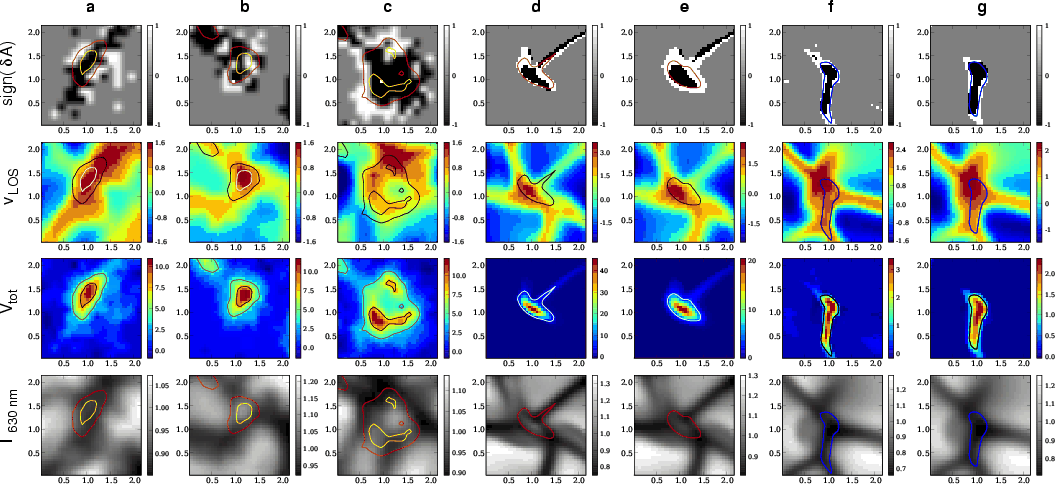
Columns a)- c): observational data obtained
with the spectro-polarimeter of Hinode/SOT. Columns d) and f):
synthetic data from the 3D MHD simulation. Columns e) and g):
same as d) and f) but after application of the SOT-PSF to the
synthetic intensity maps. Rows from top to bottom: the
sign of the Stokes-V area asymmetry for the line Fe I 630.25 nm, where
black and white correspond to negative and positive, respectively, the
Fe I 630.15 nm line-wing velocity in km s-1,
|
| Open with DEXTER | |
In the text
![\begin{figure}
\par\includegraphics[width=70mm]{8371fig2.eps}\end{figure}](/articles/aa/full/2007/48/aa8371-07/img27.gif) |
Figure 2:
Variation in |
| Open with DEXTER | |
In the text
![\begin{figure}
\par\includegraphics[width=73mm]{8371fig3.eps}\end{figure}](/articles/aa/full/2007/48/aa8371-07/img30.gif) |
Figure 3:
Vertical cross section through the simulation box corresponding
to position
|
| Open with DEXTER | |
In the text
| |
Figure 4:
Stokes-V profiles from the Hinode data across the magnetic element
of column b of Fig. 1.
|
| Open with DEXTER | |
In the text