A&A 458, 687-716 (2006)
DOI: 10.1051/0004-6361:20053891
Instrument, method, brightness, and polarization maps
from the 2003 flight of BOOMERanG
S. Masi1 - P. A. R. Ade2 - J. J. Bock3 - J. R. Bond4 - J. Borrill5,6 -
A. Boscaleri7 - P. Cabella8 - C. R.
Contaldi4,9 - B. P. Crill10 - P. de
Bernardis1 - G. De Gasperis8 - A. de
Oliveira-Costa11 - G. De Troia1 - G. Di
Stefano12 - P. Ehlers13 - E. Hivon10 - V.
Hristov14 - A. Iacoangeli1 - A. H. Jaffe9 - W. C.
Jones14 - T. S. Kisner15,16 - A. E.
Lange14 - C. J. MacTavish17 - C. Marini
Bettolo1 - P. Mason14 - P. D. Mauskopf2 - T. E.
Montroy15 - F. Nati1 - L. Nati1 - P.
Natoli8,18 - C. B. Netterfield13,17 - E.
Pascale17 - F. Piacentini1 - D.
Pogosyan4,19 - G. Polenta1 - S.
Prunet20 - S. Ricciardi1 - G. Romeo12 - J. E.
Ruhl15 - P. Santini1 - M. Tegmark11 - E.
Torbet16 - M. Veneziani1 - N.
Vittorio8,18
1 - Dipartimento di Fisica, Universita' di Roma La
Sapienza, Roma, Italy
2 - School of Physics and Astronomy, Cardiff University, Wales,
UK
3 - Jet Propulsion Laboratory, Pasadena, CA, USA
4 - Canadian Institute for Theoretical Astrophysics (CITA),
University of Toronto, ON, Canada
5 - Computational Research Division, Lawrence Berkeley National
Laboratory, Berkeley, CA, USA
6 - Space Sciences Laboratory, University of California,
Berkeley, CA, USA
7 - IFAC-CNR, Firenze, Italy
8 - Dipartimento di Fisica, Universita' di Roma Tor Vergata,
Roma, Italy
9 - Department of Physics, Imperial College, London, UK
10 - Infrared Processing and Analysis Center, California
Institute of Technology, Pasadena, CA, USA
11 - Department of Physics, Massachusetts Institute of
Technology, Cambridge, MA, USA
12 - Istituto Nazionale di Geofisica e Vulcanologia, Roma,
Italy
13 - Department of Astronomy and Astrophysics, University of
Toronto, ON, Canada
14 - Department of Astronomy, California Institute of
Technology, Pasadena, CA, USA
15 - Physics Department, Case Western Reserve University,
Cleveland, OH, USA
16 - Department of Physics, University of California, Santa
Barbara, CA, USA
17 - Department of Physics, University of Toronto, ON, Canada
18 - INFN, Sezione di Roma 2, Roma, Italy
19 - Department of Physics, University of Alberta, Edmonton,
AB, Canada
20 - Institut d'Astrophysique de Paris, Paris, France
Received 23 July 2005 / Accepted 12 July 2006
Abstract
Aims. We present the BOOMERan G-03 experiment, and the maps of the Stokes parameters I, Q, U of the microwave sky obtained during a 14 day balloon flight in 2003.
Methods. Using a balloon-borne mm-wave telescope with polarization sensitive bolometers, three regions of the southern sky were surveyed: a deep survey ( 90 square degrees) and a shallow survey (750 square degrees) at high Galactic latitudes (both centered at
 ,
,
 )
and a survey of 300 square degrees across the Galactic plane at
)
and a survey of 300 square degrees across the Galactic plane at
 ,
,
 .
All three surveys were carried out in three wide frequency bands centered at 145, 245 and 345 GHz, with an angular resolution of
.
All three surveys were carried out in three wide frequency bands centered at 145, 245 and 345 GHz, with an angular resolution of
 .
.
Results. The 145 GHz maps of Stokes I are dominated by Cosmic Microwave Background (CMB) temperature anisotropy, which is mapped with high signal to noise ratio. The measured anisotropy pattern is consistent with the pattern measured in the same region by BOOMERan G-98 and by WMAP. The 145 GHz maps of Stokes Q and U provide a robust statistical detection of polarization of the CMB when subjected to a power spectrum analysis. The amplitude of the detected polarization is consistent with that of the CMB in the  CDM cosmological scenario. At 145 GHz, in the CMB surveys, the intensity and polarization of the astrophysical foregrounds are found to be negligible with respect to the cosmological signal. At 245 and 345 GHz we detect ISD emission correlated to the 3000 GHz IRAS/DIRBE maps, and give upper limits for any other non-CMB component. When compared to monitors of different interstellar components, the intensity maps of the surveyed section of the Galactic plane show that a variety of emission mechanisms is present in that region.
Key words: instrumentation: polarimeters - techniques: polarimetric -
ISM: clouds - ISM: HII regions - cosmic microwave background
The Cosmic Microwave Background (CMB) is a remnant of the early
Universe. Its existence is one of the pillars of the current Hot
Big Bang model; its spectrum, temperature anisotropy, and
polarization carry information about the fundamental properties of
the Universe. The power spectrum of the temperature anisotropy of
the CMB,
 ,
is characterized by a flat plateau
at scales larger than the horizon at recombination (
,
is characterized by a flat plateau
at scales larger than the horizon at recombination (
 ;
;
 ), where primordial perturbations froze
early in the history of the Universe, and by a series of peaks and
dips at sub-horizon scales: the signatures of acoustic
oscillations of the primeval plasma. Measurements of angular power
spectrum have been very effective in constraining cosmological
parameters (see e.g. de Bernardis et al. 1994; Bond
et al. 1998, 2000; Dodelson & Knox 2000; Tegmark & Zaldarriaga 2000a,b, Bridle et al. 2001; Douspis et al. 2001; Lange et al. 2001; Jaffe et al. 2001; Lewis & Bridle 2004; Netterfield et al. 2002; Ruhl et al. 2003; Spergel et al. 2003; Bennet et al. 2003; Tegmark et al. 2004; Spergel et al. 2006). However, the
temperature anisotropy power spectrum is degenerate in some of
these parameters; independent cosmological information is required
to break the degeneracy (Efsthatiou & Bond 1999).
All these studies make specific assumptions on the type of the
initial conditions (adiabatic, or isocurvature) and on the shape
of the power spectrum of the initial perturbations (power-law,
scale-invariance, running index, etc.). When such assumptions are
relaxed, the determination of the cosmological parameters becomes
much more uncertain (see e.g. Bucher et al. 2002).
), where primordial perturbations froze
early in the history of the Universe, and by a series of peaks and
dips at sub-horizon scales: the signatures of acoustic
oscillations of the primeval plasma. Measurements of angular power
spectrum have been very effective in constraining cosmological
parameters (see e.g. de Bernardis et al. 1994; Bond
et al. 1998, 2000; Dodelson & Knox 2000; Tegmark & Zaldarriaga 2000a,b, Bridle et al. 2001; Douspis et al. 2001; Lange et al. 2001; Jaffe et al. 2001; Lewis & Bridle 2004; Netterfield et al. 2002; Ruhl et al. 2003; Spergel et al. 2003; Bennet et al. 2003; Tegmark et al. 2004; Spergel et al. 2006). However, the
temperature anisotropy power spectrum is degenerate in some of
these parameters; independent cosmological information is required
to break the degeneracy (Efsthatiou & Bond 1999).
All these studies make specific assumptions on the type of the
initial conditions (adiabatic, or isocurvature) and on the shape
of the power spectrum of the initial perturbations (power-law,
scale-invariance, running index, etc.). When such assumptions are
relaxed, the determination of the cosmological parameters becomes
much more uncertain (see e.g. Bucher et al. 2002).
There is additional information encoded in the linear polarization
properties of the CMB. CMB photons are last scattered at
 .
In Thomson scattering, any local quadrupole anisotropy in
the unpolarized incoming photons creates a degree of linear
polarization in the scattered photons. The main term of the local
anisotropy due to density (scalar) fluctuations is dipole, while
the quadrupole term is much smaller. For this reason the expected
polarization is quite weak (Rees 1968; Kaiser 1983; Hu & White 1997; Kamionkowski
1997; Zaldarriaga 2003). The
polarization field can be expanded into a curl-free component
(E-modes) and a curl component (B-modes). Six auto and cross power
spectra can be obtained from these components:
,
.
In Thomson scattering, any local quadrupole anisotropy in
the unpolarized incoming photons creates a degree of linear
polarization in the scattered photons. The main term of the local
anisotropy due to density (scalar) fluctuations is dipole, while
the quadrupole term is much smaller. For this reason the expected
polarization is quite weak (Rees 1968; Kaiser 1983; Hu & White 1997; Kamionkowski
1997; Zaldarriaga 2003). The
polarization field can be expanded into a curl-free component
(E-modes) and a curl component (B-modes). Six auto and cross power
spectra can be obtained from these components:
,
 ,
,
 ,
,
 ,
,
 ,
and
,
and
 .
Due to
the parity properties of these components, standard cosmological
models have
.
Due to
the parity properties of these components, standard cosmological
models have
 and
and
 .
Linear scalar (density) perturbations can only produce E-modes of
polarization (see e.g. Seljak 1997). In the concordance
model,
.
Linear scalar (density) perturbations can only produce E-modes of
polarization (see e.g. Seljak 1997). In the concordance
model,
 ,
making
a very difficult observable to measure.
Tensor perturbations (gravitational waves) produce both E-modes
and B-modes. If inflation happened (see e.g. Mukhanov & Chibisov
1981; Guth & Pi 1982; Linde 1983;
Kolb & Turner 1990), it produced a weak background of
gravitational waves. The resulting level of the B-modes depends on
the energy scale of inflation, but is in general very weak (see
e.g. Copeland et al. 1993a,b; Turner 1993).
Alternative scenarios, like the cyclic model of Steinhardt &
Turok (2002), do not produce B-modes at all (Boyle
et al. 2004).
,
making
a very difficult observable to measure.
Tensor perturbations (gravitational waves) produce both E-modes
and B-modes. If inflation happened (see e.g. Mukhanov & Chibisov
1981; Guth & Pi 1982; Linde 1983;
Kolb & Turner 1990), it produced a weak background of
gravitational waves. The resulting level of the B-modes depends on
the energy scale of inflation, but is in general very weak (see
e.g. Copeland et al. 1993a,b; Turner 1993).
Alternative scenarios, like the cyclic model of Steinhardt &
Turok (2002), do not produce B-modes at all (Boyle
et al. 2004).
Sensitive measurements of the polarization spectra will provide a
confirmation of the current scenario of acoustic oscillations in
the early universe and improve the determination of cosmological
parameters, in particular those related to the optical depth and
reionization (see e.g. Kaplinghat et al. #kaplinghat03<#393).
They will help also in detecting deviations from a simple
power-law spectrum of the initial perturbations. Moreover, they
will allow study of the detailed mix of adiabatic and isocurvature
initial perturbations (Gordon & Lewis 2003; Peiris et al. 2003). The detection of
will probe
the gravitational lensing of E-modes (Zaldarriaga & Seljak
1998), and, if present, the inflation generated
component (Leach & Liddle 2003; Song & Knox
2003).
Confusion by galactic foregrounds will ultimately limit the
precision with which
and
can be measured. Not much is known about the galactic polarized
background at microwave frequencies. The two mechanisms producing
diffuse brightness of the interstellar medium are synchrotron
radiation from relativistic electrons and thermal emission from
dust.
The former is sampled at low frequencies. Patchy high latitude
observations at frequencies between 0.408 and 1.411 GHz are
collected in Brouw & Spoelstra (1976). New observations
carried out with the ATCA telescope at 1.4 GHz (Bernardi et al. 2003) and at 2.3 GHz (Carretti et al. 2005)
in the same high galactic latitude region observed by our
experiment show that the polarized synchrotron emission is very
weak. A naive extrapolation to 145 GHz predicts a polarization of
0.2  K rms, small with respect to the
 expected in the concordance model.
Polarized emission of galactic dust has been detected in the 353 GHz survey of Archeops in the Galactic Plane (Benoit et al. 2003) and at high galactic latitudes (Ponthieu et al. 2005). There,
has been detected
at a level of 2 ,
while only an upper limit was obtained
for
.
The polarized dust emission
,
while only an upper limit was obtained
for
.
The polarized dust emission
 extrapolated to 145 GHz is quite weak, less
than 1 K rms. While the foreground signals are expected to be
smaller than the CMB signal at 145 GHz, they should not be ignored
for future, very precise measurements of CMB polarization. To do
this, multiband measurements will be mandatory.
extrapolated to 145 GHz is quite weak, less
than 1 K rms. While the foreground signals are expected to be
smaller than the CMB signal at 145 GHz, they should not be ignored
for future, very precise measurements of CMB polarization. To do
this, multiband measurements will be mandatory.
After a long pioneering phase (Caderni et al. 1978; Nanos
1979; Lubin & Smoot 1981; Masi 1984;
Partridge et al. 1988; Netterfield et al. 1995; Wollak et al. 1997), the measurement of
CMB polarization is today a rapidly growing field; new interest
has been sparked especially by the possibility of detecting the
signature of the inflationary gravity wave
background (Keating et al. 2001; Subrahmanyan et al. 2000; Hedman et al. 2002; Piccirillo et al. 2002; Delabrouille et al. 2002; Masi
et al. 2002; Villa et al. 2002; Kovac et al. 2002; Johnson et al. 2003; Keating et al. 2003; Kogut et al. 2003; Farese et al. 2004;
Leitch et al. 2005; Barkats et al. 2005; Readhead
et al. 2004; Cortiglioni et al. 2004;
Cartwright et al. 2005). To date, statistically
significant detections of CMB polarization have been reported by
the experiments DASI, CAPMAP, CBI and WMAP, all using coherent
techniques. DASI has detected
at 2.9and
at 6.3
(Leitch et al. 2005); CAPMAP (Barkats et al. 2005) has
detected
at  ;
CBI (Readhead
et al. 2004) has detected
at
;
CBI (Readhead
et al. 2004) has detected
at

 ;
WMAP has detected
at many
(Kogut et al. 2003), and
at
several
(Page et al. 2006). The polarization power
spectra measured by these experiments are all consistent with the
forecast from the "concordance'' model best fitting the WMAP
power spectrum. Their precision, however, is
not yet good enough to improve significantly the constraints on
the cosmological parameters. The only exception is the
measurement by WMAP at large angular scales, which
provides evidence for an early, complex reionization of the
universe (Kogut et al. 2003; Kaplinghat et al. 2003). The detailed structures in the
spectrum are still to be confirmed, and we are very far
from the sensitivity required to constrain the initial conditions
or inflation.
;
WMAP has detected
at many
(Kogut et al. 2003), and
at
several
(Page et al. 2006). The polarization power
spectra measured by these experiments are all consistent with the
forecast from the "concordance'' model best fitting the WMAP
power spectrum. Their precision, however, is
not yet good enough to improve significantly the constraints on
the cosmological parameters. The only exception is the
measurement by WMAP at large angular scales, which
provides evidence for an early, complex reionization of the
universe (Kogut et al. 2003; Kaplinghat et al. 2003). The detailed structures in the
spectrum are still to be confirmed, and we are very far
from the sensitivity required to constrain the initial conditions
or inflation.
The CMB polarization signals are so small with respect to the
noise of current experiments that systematic effects are of
particular concern. Consistent detection by experiments using very
different techniques is important. This has been achieved only
recently for CMB temperature anisotropy measurements, where the
data obtained by DASI, CBI and WMAP at frequencies  100 GHz are perfectly consistent with the bolometric maps obtained by
BOOMERan G, MAXIMA, ACBAR and Archeops at 150 GHz (de Bernardis et al. 2003; Abroe et al. 2003; Kuo et al. 2002; Hamilton et al. 2003).
100 GHz are perfectly consistent with the bolometric maps obtained by
BOOMERan G, MAXIMA, ACBAR and Archeops at 150 GHz (de Bernardis et al. 2003; Abroe et al. 2003; Kuo et al. 2002; Hamilton et al. 2003).
All detections of CMB polarization to date have been made using
coherent detectors at frequencies 100 GHz. In this paper
we describe a completely orthogonal experiment that has, for the
first time, detected the CMB polarization at frequencies  100 GHz. The experiment is a modification of the BOOMERanG experiment
that produced the first resolved images of the CMB (de Bernardis
et al. 2000) and allowed the first detailed
extraction of cosmological parameters from the CMB (Lange et al. 2001). The modified experiment, flown in January 2003
and hereafter referred to as B03, is sensitive to polarization in
three bands centered at 145, 245 and 345 GHz. We present here the
measurement method, the instrument, and the maps of the Stokes
parameters I, Q, U of the CMB detected by B03 in the 2003
campaign.
100 GHz. The experiment is a modification of the BOOMERanG experiment
that produced the first resolved images of the CMB (de Bernardis
et al. 2000) and allowed the first detailed
extraction of cosmological parameters from the CMB (Lange et al. 2001). The modified experiment, flown in January 2003
and hereafter referred to as B03, is sensitive to polarization in
three bands centered at 145, 245 and 345 GHz. We present here the
measurement method, the instrument, and the maps of the Stokes
parameters I, Q, U of the CMB detected by B03 in the 2003
campaign.
Maps of CMB anisotropy and polarization are an important step in
compressing the cosmological information into power spectra, but
they are also important on their own. Maps are essential for
understanding systematic effects in the measurement and the level
of foreground contamination, and can be used to test the
Gaussianity of the CMB fluctuations (see e.g. Polenta et al. 2002; De Troia et al. 2003; Komatsu et al. 2003; Aliaga et al. 2003; Savage et al. 2004).
Estimates of the power spectra
,
and
from B03 are described in three
companion papers (Jones et al. 2006a; Piacentini et al. 2006; Montroy et al. 2006), and the
resulting constraints on cosmological parameters in a further
paper (Mac Tavish et al. 2006).
2.1 Generality
This instrument derives directly from the BOOMERan G payload flown in
1997 (Piacentini et al. 2002) and in 1998 (Crill et al. 2003). That instrument provided the first high
signal-to-noise maps of the CMB anisotropy with sub-horizon
resolution (de Bernardis et al. 2000; Netterfield et al. 2002; Ruhl et al. 2003), and identified
three peaks in the angular power spectrum of the CMB (de Bernardis
et al. 2002; Ruhl et al. 2003). After the
1998/1999 flight, the instrument was recovered and modified to
make it sensitive to polarization and to improve the attitude
reconstruction hardware. In this section we describe the different
subsystems, with focus on the new ones.
B03 is a scanning polarimeter, composed of an off-axis, 1.3 m
diameter mm-wave telescope, a cryogenic multi-band bolometric
receiver, and an attitude control system. The latter is able to
control the azimuth and elevation of the telescope while the
payload is floating in the stratosphere, at an altitude of
30 km, under a long duration stratospheric balloon.
We use the sky scan to modulate the signal. We map the anisotropy
of the linear polarization by means of two separate bolometers,
B1 and B2, that observe the sky through the same feed
structure but are sensitive to orthogonal polarization directions.
This device is called a Polarization Sensitive Bolometer (PSB,
Jones et al. 2003). Each bolometer signal is processed and
amplified separately.
In principle, we can then difference the two signals to obtain the
Stokes parameter Q of linear polarization. The U parameter is
measured by means of an identical PSB, containing bolometers B3and B4, rotated by  in the focal plane with respect to
the first one. In this minimal set of four bolometers, the
principal axis of each sensor is rotated with respect to the focal
plane by an angle
in the focal plane with respect to
the first one. In this minimal set of four bolometers, the
principal axis of each sensor is rotated with respect to the focal
plane by an angle  .
For the first PSB
.
For the first PSB
 and
and
 ;
for the second one
;
for the second one
 and
and
 .
.
In practice, our sky scan strategy uses repeated scans over the
same sky pixel p. At different times ti during the
survey, the focal plane rotates with respect to the sky by an
angle  .
Information on Q and U in each sky pixel thus
comes from all the bolometers present in the focal plane, according
to the relation
.
Information on Q and U in each sky pixel thus
comes from all the bolometers present in the focal plane, according
to the relation
![\begin{displaymath}V^p_{i,k} \!=\! {1 \over 2} \mathcal{S}_k \left[ I_p + Q_p \c...
...amma_i)] + U_p \sin[2 (\alpha_k+\gamma_i)] \right] +
n_{i,k} .
\end{displaymath}](/articles/aa/full/2006/42/aa3891-05/img81.gif) |
(1) |
Here Vpi,k is the signal measured by bolometer k at time
ti;
 is the responsivity of bolometer k;
Ip, Qp, Up are the Stokes parameters of pixel p in the
chosen celestial coordinates, and ni,k is the noise
contribution to the ith measurement on that pixel. This system
of equations can be inverted and the Stokes parameters estimated
if a sufficient number of measurements over a range of angles
is the responsivity of bolometer k;
Ip, Qp, Up are the Stokes parameters of pixel p in the
chosen celestial coordinates, and ni,k is the noise
contribution to the ith measurement on that pixel. This system
of equations can be inverted and the Stokes parameters estimated
if a sufficient number of measurements over a range of angles
 is taken.
Other ways to modulate the polarization involve the use of a
modulating analyzer to extract the polarized component by
synchronous demodulation. Rotating wire grids, half wave plates,
K-mirrors, Faraday rotators, Fresnel rombs, have been used or
proposed as polarization analyzers (see e.g. Keating et al. 2003; Battistelli et al. 2002; Hanany
et al. 2003; Gervasi et al. 2003; Gundersen et al. 2003; Catalano et al. 2004). While all of
these techniques can in principle provide a valuable means of
reducing requirements on the stability of detector gains and
offsets, they come at a cost in both complexity and bandwidth.
Correlation polarimeters have so far been implemented only with
coherent detectors (see e.g. Carretti et al. 2001; Padin
et al. 2002).
The polarization measurement strategy defined by
Eq. (1) is prone to leakage of the unpolarized
component I into the polarized ones Q and U, if the
responsivities
are not known exactly. Similarly,
errors in the principal axes angles
mix Q and Uinto each other. The polarimetric calibration consists of
measuring all
and .
The precision
required to obtain the common-mode rejection needed in our case
can be estimated as follows.
For simplicity we choose the reference frame to have  ,
and we consider the pair of detectors with
,
and we consider the pair of detectors with
 .
In this case we can't recover all the parameters
but only I and Q. Equation (1) becomes
.
In this case we can't recover all the parameters
but only I and Q. Equation (1) becomes
![$\displaystyle V_1 = {\mathcal{S}_1 \over 2} \left[I + Q \right] ={\mathcal{S} \over 2} \left[I + Q \right]$](/articles/aa/full/2006/42/aa3891-05/img86.gif) |
|
|
(2) |
![$\displaystyle V_2 = {\mathcal{S}_2 \over 2} \left[I - Q \right] = {\mathcal{ S
R } \over 2} \left[I - Q \right]$](/articles/aa/full/2006/42/aa3891-05/img87.gif) |
|
|
(3) |
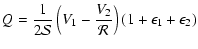
where we have expressed the
calibration constants in terms of an absolute calibration
 and a relative calibration
 .
The solution is
.
The solution is
![$\displaystyle I = \frac 1{\mathcal S} \left[V_1 + \frac{V_2}{\mathcal R}
\right]$](/articles/aa/full/2006/42/aa3891-05/img90.gif) |
|
|
(4) |
 |
|
|
(5) |
Uncertainties on the calibration constant
 and on the relative calibration
 are
propagated in the error on Q by
are
propagated in the error on Q by
 |
(6) |
Using
 (true if
  )
)
 |
(7) |
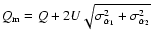
For E-mode polarization we expect to have a factor I/Q of the
order of 20. If we want to achieve a  accuracy in the
determination of Q and U, we need to have
accuracy in the
determination of Q and U, we need to have
 for each detector. We show below that
relative calibration constants can be measured within an error of
2% by comparing the CMB temperature anisotropy measured
in different detectors (see Sect. 7.2.2). The absolute
calibration
for each detector. We show below that
relative calibration constants can be measured within an error of
2% by comparing the CMB temperature anisotropy measured
in different detectors (see Sect. 7.2.2). The absolute
calibration
 has to be determined with a relative
error
has to be determined with a relative
error
 .
.
From Eq. (1) we can also estimate the acceptable
principal axis angle uncertainty. Again we choose the reference
frame to have ,
and we consider the couple of detectors
with
,
with errors
 and
and
 .
To first order the measured Stokes
parameter
.
To first order the measured Stokes
parameter  will be
 ,
i.e.
,
i.e.
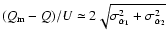 .
From this
equation we see that
.
From this
equation we see that
 produces an
error in Q (and U) .
Mixing Q and U also mixes E
and B-mode signals, so errors in alpha may affect the level at
which one can set an upper limit on the B-mode polarization
anisotropy signal.
produces an
error in Q (and U) .
Mixing Q and U also mixes E
and B-mode signals, so errors in alpha may affect the level at
which one can set an upper limit on the B-mode polarization
anisotropy signal.
Non-ideal polarized detectors have a residual sensitivity to the
polarization component orthogonal to the principal axis
(cross-polar response). As we rotate a perfect polarizing grid in
front of a non ideal polarization sensitive detector, the detector
response is given by a modified Malus law:
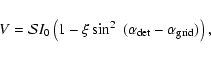 |
(8) |
where
is the responsivity, I0 is the incident
power and  is the polarization efficiency.
 is
the angle of the main axis of the detector with respect to the x
axis of the reference frame, and
is
the angle of the main axis of the detector with respect to the x
axis of the reference frame, and
 is the position
of the principal axis of the polarizing grid.
is the position
of the principal axis of the polarizing grid.
This can be rewritten in terms of the cross-polar response
coefficient
 defining the
response of the detector to radiation polarized orthogonally to
its main axis, as a fraction of the response to radiation
polarized parallel to its main axis. We have
defining the
response of the detector to radiation polarized orthogonally to
its main axis, as a fraction of the response to radiation
polarized parallel to its main axis. We have
 .
Using an operative definition of responsivity
.
Using an operative definition of responsivity
 we rewrite
![\begin{displaymath}
V=\mathcal{S^\prime}I_0\left[ 1 +
\frac{1-\epsilon}{1+\epsilon} \cos~(2(\alpha_{\rm det} -
\alpha_{\rm grid})) \right].
\end{displaymath}](/articles/aa/full/2006/42/aa3891-05/img115.gif) |
(9) |
Taking into account cross-polar response, and dropping the  for simplicity, Eq. (1) becomes
![\begin{displaymath}
V_k = {\mathcal{S}_k \over 2} \left[ I + Q
\frac{1-\epsilon_...
...
\frac{1-\epsilon_k}{1+\epsilon_k} \sin~(2\alpha) \right]+n_k.
\end{displaymath}](/articles/aa/full/2006/42/aa3891-05/img116.gif) |
(10) |
This system can be inverted to measure Q, U, and I if the
cross-polar response coefficients
 are known. In the
same simplified case considered above the system becomes
are known. In the
same simplified case considered above the system becomes
![$\displaystyle V_1 = \mathcal{S} \left[I +
\frac{1-\epsilon_1}{1+\epsilon_1} Q \right]$](/articles/aa/full/2006/42/aa3891-05/img118.gif) |
|
|
(11) |
![$\displaystyle V_2 =
\mathcal{R S} \left[I - \frac{1-\epsilon_2}{1+\epsilon_2} Q
\right].$](/articles/aa/full/2006/42/aa3891-05/img119.gif) |
|
|
(12) |
Assuming that
 and
and
 are
known, this is solved by
are
known, this is solved by
![$\displaystyle I= \frac 1{2\mathcal S} \left[V_1 \left(
\frac{1-\epsilon_2}{1+\e...
...eft( \frac{1-\epsilon_1}{1+\epsilon_1} \right)\right]
(1+\epsilon_1+\epsilon_2)$](/articles/aa/full/2006/42/aa3891-05/img122.gif) |
|
|
(13) |
 |
|
|
(14) |
where the terms of the second order in  have been neglected. Proceeding as above, we find
 |
(15) |
We conclude that in our case
the uncertainty on the cross-polar response parameters can be
 .
All the conclusions obtained
in this section have been verified by means of numerical
simulations with realistic parameters (Masi et al. 2002).
.
All the conclusions obtained
in this section have been verified by means of numerical
simulations with realistic parameters (Masi et al. 2002).
Scanning the sky with AC-coupled detectors is an effective way to
measure the intensity and polarization of the sky at the angular
scales of interest for the CMB. This strategy has been used by
BOOMERan G-98 and Archeops, is in use in QuAD, and will be used by
Planck-HFI and LFI.
In the case of B03, we scan the sky rotating the full payload in
azimuth, so that atmospheric emission is almost constant along the
scan. Working with an AC coupled amplifier, our system is
insensitive to constant signals.
We alternate forward and reverse scans to map the low foreground
region already observed by BOOMERan G-98, centered in the
constellations Caelum and Horologium, at
 ,
(
,
(
 ). During Antarctic LDB flights,
the average latitude of the payload is
). During Antarctic LDB flights,
the average latitude of the payload is
 .
In one day,
due to sky rotation, this procedure produces a highly cross-linked
scan pattern (see Crill et al. 2003, Fig. 9), which is
important for map making.
.
In one day,
due to sky rotation, this procedure produces a highly cross-linked
scan pattern (see Crill et al. 2003, Fig. 9), which is
important for map making.
2.2 Observation strategy optimization
Our sky coverage is optimized to reduce the errors on the CMB
power spectra given the constraints imposed by our telescope's
hardware and the presence of bright celestial sources (the Sun and
Galaxy). With the assumption of uniform sky coverage and
uncorrelated noise from pixel to pixel and between T, Q and U, the
errors on
 are approximated by Zaldarriaga & Seljak
(1997):
are approximated by Zaldarriaga & Seljak
(1997):
![\begin{displaymath}\sigma_{E,\ell}^2=\frac{2}{(2\ell+1)f_{{\rm sky}}}\left[{C_{E...
...l}+\frac{4{\pi}f_{{\rm sky}}{N_E}^2}{\tau
B_\ell^2} }\right]^2
\end{displaymath}](/articles/aa/full/2006/42/aa3891-05/img131.gif) |
(16) |
and the errors on
 are given by
![$\displaystyle \sigma_{X,\ell}^2 =
\frac{2}{(2\ell+1)f_{{\rm sky}}} \left[{C_{X,...
...t({C_{E,\ell}+\frac{4{\pi}f_{{\rm sky}}{N_E}^2}{\tau
B_\ell^2}}\right)} \right]$](/articles/aa/full/2006/42/aa3891-05/img133.gif) |
|
|
(17) |
where NT and NE are the effective noise equivalent
temperatures in T and E of the combined set of detectors;
 is the integration time spent uniformly covering the
 fraction of the sky, and
  is the beam response
in multipole space. For the case of B03,
is the beam response
in multipole space. For the case of B03,
 since there are eight linear detectors arranged in four orthogonal
pairs, each with a different orientation on the sky (see Fig. 5). If we use an estimate of our detector
sensitivity and flight time (both based on the previous flights of
BOOMERan G), and a set of power spectra based on the best models to
date, then we can calculate the uniform sky coverage needed to
maximize the signal to noise ratio near the first peaks of
and
.
The signal to noise ratios for those band-powers are a
fairly flat function of the sky coverage. The signal to noise
ratio for
peaks near
since there are eight linear detectors arranged in four orthogonal
pairs, each with a different orientation on the sky (see Fig. 5). If we use an estimate of our detector
sensitivity and flight time (both based on the previous flights of
BOOMERan G), and a set of power spectra based on the best models to
date, then we can calculate the uniform sky coverage needed to
maximize the signal to noise ratio near the first peaks of
and
.
The signal to noise ratios for those band-powers are a
fairly flat function of the sky coverage. The signal to noise
ratio for
peaks near
 square
degrees. For
,
the peak is near
square
degrees. For
,
the peak is near
 square degrees (see Figs. 1 and 2).
![\begin{figure}
\par\includegraphics[width=7.2cm,clip]{3891f01a.eps}
\end{figure}](/articles/aa/full/2006/42/aa3891-05/Timg139.gif) |
Figure 1:
The signal to noise ratio vs. sky coverage for the
computed using the best estimate of NE. The three curves
refer to different
 bandpowers, and are labelled
using the center multipole. These multipoles correspond to peaks
in the "concordance''
power spectrum.
bandpowers, and are labelled
using the center multipole. These multipoles correspond to peaks
in the "concordance''
power spectrum. |
| Open with DEXTER |
The BOOMERan G telescope has a useable elevation range of 35 to 55
degrees. The telescope is designed to scan no more than 60 from the anti-sun direction. Exceeding this range
could cause heating of the telescope baffles by sunlight. There
are also constraints on the acceptable scan periods of the
telescope. From the 1998 flight of BOOMERan G, we know that certain
scan periods excite pendulations in the balloon-gondola system.
The scan speed is restricted by the thermal time constants of the
detectors, the mechanics of the telescope control systems, and the
stability of our readout electronics.
from the anti-sun direction. Exceeding this range
could cause heating of the telescope baffles by sunlight. There
are also constraints on the acceptable scan periods of the
telescope. From the 1998 flight of BOOMERan G, we know that certain
scan periods excite pendulations in the balloon-gondola system.
The scan speed is restricted by the thermal time constants of the
detectors, the mechanics of the telescope control systems, and the
stability of our readout electronics.
Given these constraints, we created a scan strategy that came as
close as possible to producing uniform coverage over both a
"deep'' region (for sensitivity to
)
and a larger
"shallow'' region (for sensitivity to
). Because each
change in pointing elevation perturbs the telescope, we decided to
adjust the elevation no more than once per hour. With this
restriction, we found that the smallest reasonable size that we
could achieve for the "deep'' region was  100 square
degrees. The size of our "shallow'' region (800square degrees) was bounded on one side by the galaxy and on the
other side by the distance from the anti-sun direction.
100 square
degrees. The size of our "shallow'' region (800square degrees) was bounded on one side by the galaxy and on the
other side by the distance from the anti-sun direction.
When determining the details of the scan strategy, we simulated
the scanning of the telescope based on the same "schedule file''
used to actually control the telescope during the flight. These
simulations produced a coverage map for a given schedule file.
Since this coverage was non-uniform, we approximated the spectral
errors by the sum of the error contributions from each pixel
![\begin{displaymath}\sigma_{E,\ell}^2 =
\sum\limits_{p}^{}\;\frac{2}{(2\ell+1)f_{...
...ft[{C_{E,\ell}+\frac{4{\pi}f_{{p}}{n_{p,E}}^2}{\tau}}\right]^2
\end{displaymath}](/articles/aa/full/2006/42/aa3891-05/img142.gif) |
(18) |
![$\displaystyle \sigma_{X,\ell}^2 =
\sum\limits_{p}^{}\;\frac{2}{(2\ell+1)f_{{p}}...
...}\right)\left({C_{E,\ell}+\frac{4{\pi}f_{{p}}{n_{p,E}}^2}{\tau}}\right)}\right]$](/articles/aa/full/2006/42/aa3891-05/img143.gif) |
|
|
(19) |
where fp is the sky fraction of a typical pixel and np,T and np,E are the noise in a given pixel computed
from the NET of the detectors and the integration time on the
pixel. We decided to spend the first four days of the flight
scanning over the "shallow'' region, and to spend the remainder
of the flight on the "deep'' region. After confirming that the
scanning schedule produced the desired sky coverage (and signal to
noise), we adjusted the scan speed so that it did not coincide
with any pendulation modes discovered in B98. Because of these
adjustments, B03 uses a range of many different azimuth scan
speeds: between 0.2 and 0.6 deg/s for the deep survey, and between
0.6 and 1 deg/s in the shallow survey.
Twice a day, when the scans over the deep and shallow regions
would be at nearly constant declination and therefore give minimal
cross-linking, the telescope was directed to scan a region
spanning the galactic plane, including RCW38 and other galactic
sources useful for calibration (see Sect. 7.4).
![\begin{figure}
\par\includegraphics[width=7.2cm,clip]{3891f02a.eps}
\end{figure}](/articles/aa/full/2006/42/aa3891-05/Timg144.gif) |
Figure 2:
The signal to noise ratio vs. sky coverage for
computed using the best estimate of NTand NE. The three curves refer to different
bandpowers, and are labelled using the center multipole. The
selected multipoles correspond to extremals in the "concordance''
power spectrum. |
| Open with DEXTER |
Cryogenic bolometers are the most sensitive detectors for
continuum mm-wave radiation (see e.g. Richards 1994).
The focal plane of B03 consists of eight optically active
bolometric receivers, two dark bolometers, and a fixed resistor,
all of which operate from a 270 mK base temperature. The
optically inactive channels are read out using identical
electronics as a check against microphonics, RFI and baseplate
temperature fluctuations. The focal plane is split equally between
two types of receivers: four (dual-polarized) Polarization
Sensitive Bolometer (PSB) pixels operating at 145 GHz, and four
(single-polarization) two-color photometers using spider-web
bolometers operating at 245 and 345 GHz.
Polarization Sensitive Bolometers consist of a pair of co-located
silicon nitride micromesh absorbers which couple anisotropically
to linearly polarized radiation through a corrugated waveguide
structure (Jones et al. 2003; Jones et al. 2006b).
The system allows simultaneous background limited measurements of
the Stokes I and Q parameters over  bandwidths. The
absorbers, separated by
bandwidths. The
absorbers, separated by 
 m, are electrically and
thermally isolated from one another. The devices used in B03 are
shown in Fig. 3.
m, are electrically and
thermally isolated from one another. The devices used in B03 are
shown in Fig. 3.
![\begin{figure}
\par\includegraphics[width=5.3cm,clip]{3891f03a.eps}
\end{figure}](/articles/aa/full/2006/42/aa3891-05/Timg148.gif) |
Figure 3:
Photograph of the radiation absorber of a Polarization
Sensitive Bolometer used in B03. The
 micromesh absorbing
grid has a diameter of 2.6 mm, the absorber leg spacing is 108
micromesh absorbing
grid has a diameter of 2.6 mm, the absorber leg spacing is 108  ,
and each leg is 3
wide. Only the vertical wires are
metalized. The horizontal wires are used for structural support
and do not absorb radiation. ,
and each leg is 3
wide. Only the vertical wires are
metalized. The horizontal wires are used for structural support
and do not absorb radiation. |
| Open with DEXTER |
The common thermal and radiative environment resulting from the
physical proximity of the two detectors provides gain stability
and rejection of differential temperature fluctuations which are
limited only by differences in the properties of the NTD Ge
thermistors and the electrical leads, which determine the thermal
conductance to the bath. Both linear polarizations propagate
through a shared waveguide structure and set of optical filters
and couple to the telescope through a cryogenic corrugated feed,
ensuring an identical electromagnetic bandpass and highly
symmetric beams. PSBs are fabricated using the same proven
photolithographic techniques used to make spider-web
bolometers (Yun et al. 2003), and enjoy the same benefits of
reduced heat capacity, low cross section to cosmic rays, and
reduced susceptibility to microphonic response relative to
monolithic bolometers.
The two-color photometer is an evolutionary development of the
photometers originally designed for MAX (Fischer et al. 1992), and used subsequently by the SuZIE (Holzapfel
et al. 1997), the FIRP instrument on the IRTS (Lange
et al. 1994), and the BOOMERan G98 (Piacentini et al. 2002; Crill et al. 2003) CMB experiments.
The B03 photometer has been optimized for only two frequencies,
and has been made polarization sensitive by the fitting of a
polarizing grid to the feed aperture. The detectors are all
similar, if not identical, to the detectors flown on BOOMERan G98. The
B03 feed design, consisting of a multi-mode back-to-back profiled
corrugated horn, is significantly advanced relative to earlier
versions of the photometer. This system achieved high
efficiencies and symmetric beam patterns over the full 200-420 GHz
bandwidth.
The radiation is coupled from the photometer feed through a 420
GHz metal mesh low-pass filter into the 12.7 mm diameter
photometer body. A dichroic filter, tilted by
 with
respect to the optical axis wavefront, directs radiation at
frequencies above 295 GHz to the 345 GHz detector module while
passing the lower frequencies to the 245 GHz detector module. The
detector modules are thermally isolated from the photometer body,
which is held near 2 K, by a 5-mm gap. The photometer
sub-Kelvin feeds are smooth walled with an exit aperture matched
to the geometric area of the absorber. Corrugated feeds are not
necessary, as the polarization discrimination and beam forming is
determined by the 2-Kelvin feed antenna.
with
respect to the optical axis wavefront, directs radiation at
frequencies above 295 GHz to the 345 GHz detector module while
passing the lower frequencies to the 245 GHz detector module. The
detector modules are thermally isolated from the photometer body,
which is held near 2 K, by a 5-mm gap. The photometer
sub-Kelvin feeds are smooth walled with an exit aperture matched
to the geometric area of the absorber. Corrugated feeds are not
necessary, as the polarization discrimination and beam forming is
determined by the 2-Kelvin feed antenna.
The two configurations used in the focal plane are presented in
Fig. 4. The performance of the receivers as
integrated in the BOOMERan G focal plane is reported in Sect. 3.
![\begin{figure}
\par\includegraphics[width=8.2cm,clip]{3891f04a.eps}
\end{figure}](/articles/aa/full/2006/42/aa3891-05/Timg150.gif) |
Figure 4:
Schematic of the 2-color
photometers ( bottom) and of the PSB polarimeters ( top) used in
B03. |
| Open with DEXTER |
Optical filtering is of critical importance to a bolometric
receiver; in addition to defining the optical pass-band, care must
be taken to ensure that the detector is shielded from out-of-band
radiation originating from within the cryostat. These filters also
play a significant role in the determination of the end-to-end
optical efficiency of the system. Finally, the optical filtering
must reduce the radiative loading on the various stages of the
cryogenic system to acceptable levels.
The window of the B03 cryostat consists of a
 polypropilene film stretched on an elliptical aluminum frame. The
window has excellent (
polypropilene film stretched on an elliptical aluminum frame. The
window has excellent ( )
transmission at all three
wavelengths but is exceedingly fragile, requiring replacement
after each cycle of the cryostat.
)
transmission at all three
wavelengths but is exceedingly fragile, requiring replacement
after each cycle of the cryostat.
Table 1:
The optical filtering scheme
employed
by B03. In order to take advantage of the low backgrounds
available at float altitudes, much care must be taken to reduce the
background originating from within the cryostat. While the metal mesh
filters, which consist of bonded layers of polyethylene, exhibit
in-band emissivities at the percent level, the PTFE antireflection
coating is several times more emissive. It is crucial that these
filters remain well
heat-sunk and protected from infrared emission from the warmer stages.
Most of the filters used in the B03 optical system consist of
layers of patterned meshes deposited on polypropylene
substrates (Lee et al. 1996), with the gaps between layers
filled by polypropylene as well. The dichroic beam-splitter used
in the photometer body is the sole exception, being an air-gap the
inductive layers are deposited on a thin Mylar substrate and
stretched on an aluminum frame. The polarizing grids used on the
photometer and in laboratory testing, and the neutral-density
filter, are made in a similar fashion. Instead of inductive or
capacitive grids, a linear pattern is used for the polarizer,
while a uniform reflective coating is used for the NDF.
The layers of the filter are hot-pressed to form a single
self-supporting filter. Some of the thicker hot-pressed filters
are antireflection coated with a tuned layer of PTFE (Teflon).
PTFE has high infrared emissivity, which initially resulted in
excessive heating of the B03 filters and a large thermal load on
the LN2 and L4He stages. In addition, the heating of the
filters led to a significant increase in background loading of the
detectors resulting from in-band thermal emission. To ameliorate
this problem, large-format, composite IR blockers were fitted in
front of the 77 K and 2 K filters. These filters have high ()
in-band transmission and reflect radiation at wavelengths
shortward of  m.
m.
To measure polarization, we combine information from spatially
separated pixels, as shown in Eq. (1). The focal plane
layout (Fig. 5) is designed to minimize spatial
separation between pixels, given the constraints of the existing
BOOMERan G optics and the size of the feed-horns. This allows for
maximal overlap of maps made by spatially separate pixels. The
wide focal plane of the B03 telescope is thus populated by 8 pixels with independent corrugated feed horn systems. Each pixel
contains two detectors. The four pairs of 145 GHz PSBs in the
lower row of detectors provide the best sensitivity for CMB
temperature and polarization anisotropy. We have introduced some
level of redundancy by using four independent PSB pairs, covering
with their principal axes the range
![$\alpha=[0,\pi]$](/articles/aa/full/2006/42/aa3891-05/img158.gif) in
in  steps. The four pixels in the upper row are 2-color photometers
operating at 245 and 345 GHz. These are included to provide a
lever arm for discriminating CMB from dusty foregrounds. Table 2 summarizes the properties of the B03 receiver.
steps. The four pixels in the upper row are 2-color photometers
operating at 245 and 345 GHz. These are included to provide a
lever arm for discriminating CMB from dusty foregrounds. Table 2 summarizes the properties of the B03 receiver.
![\begin{figure}
\par\includegraphics[width=7.2cm,clip]{3891f05a.eps}
\end{figure}](/articles/aa/full/2006/42/aa3891-05/Timg160.gif) |
Figure 5:
Focal Plane Schematic.
2-color photometers with band centers at 245 GHz and 345 GHz
populate the upper row. Each photometer is only sensitive to one
polarization. The lower row has 4 pairs of PSB's. The elements in
a PSB pair are sensitive to orthogonal polarizations. The circles
representing the pixels show relative beams sizes:
 for both photometer channels and
 for
the PSB's. The arrows through the circles show the orientation of
the principal axis of polarization. Thephotometer and PSB rows
are separated by
for
the PSB's. The arrows through the circles show the orientation of
the principal axis of polarization. Thephotometer and PSB rows
are separated by
 in elevation, while the pixels in a
row are separated by
in cross-elevation. The labels
ofthe two bolometers used for each pixel are also reported.
in elevation, while the pixels in a
row are separated by
in cross-elevation. The labels
ofthe two bolometers used for each pixel are also reported. |
| Open with DEXTER |
2.6 Telescope, beam, and optics polarization properties
The BOOMERan G telescope is an off-axis system, minimizing the
radiative loading on the detectors. Its configuration is close to
the Dragone condition (Dragone 1974, 1982), which nulls the
cross-polar response in the center of the focal plane. However,
the need to accommodate a large number of detectors in the focal
plane drove our optimization towards a wide corrected focal plane
rather than nulling the cross-polar response only in the center.
We optimized the optics for diffraction limited performance at
1 mm over a
 field of view. Radiation
from the sky is reflected by the parabolic primary mirror (1.3 m
diameter, f=1280 mm, 45
off-axis) and enters the cryostat
through a thin (50 m) polypropylene window near the prime
focus. Inside the cryostat, at 2 K, the fast off-axis secondary
(elliptical) and tertiary (parabolic) mirrors re-image the prime
focus onto the detector focal plane. They are also configured to
form an image of the primary mirror at the 10 cm diameter tertiary
mirror, which is the Lyot-stop of the system. In the center of the
tertiary mirror a 1 cm diameter hole hosts a thermal
calibration source (callamp) which is flashed at fixed intervals
during the flight (see Crill et al. 2003 for details). The
size of the tertiary mirror therefore limits the illumination
pattern on the primary mirror, which is under-filled by 50% in
area (85 cm in diameter) to improve the rejection of side-lobes.
This is further improved by cold absorbing baffles surrounding the
cold mirrors and rejecting stray light. Detailed parameters of the
optics are described in Piacentini et al. (2002) and
Crill et al. (2003).
field of view. Radiation
from the sky is reflected by the parabolic primary mirror (1.3 m
diameter, f=1280 mm, 45
off-axis) and enters the cryostat
through a thin (50 m) polypropylene window near the prime
focus. Inside the cryostat, at 2 K, the fast off-axis secondary
(elliptical) and tertiary (parabolic) mirrors re-image the prime
focus onto the detector focal plane. They are also configured to
form an image of the primary mirror at the 10 cm diameter tertiary
mirror, which is the Lyot-stop of the system. In the center of the
tertiary mirror a 1 cm diameter hole hosts a thermal
calibration source (callamp) which is flashed at fixed intervals
during the flight (see Crill et al. 2003 for details). The
size of the tertiary mirror therefore limits the illumination
pattern on the primary mirror, which is under-filled by 50% in
area (85 cm in diameter) to improve the rejection of side-lobes.
This is further improved by cold absorbing baffles surrounding the
cold mirrors and rejecting stray light. Detailed parameters of the
optics are described in Piacentini et al. (2002) and
Crill et al. (2003).
Table 2:
Summary of the properties of the B03 receiver. The
noise reported in the last column is for a frequency of 1 Hz and
is the average noise of all the detectors at that frequency.
We have studied the beams and polarization properties of this
system by means of the physical optics code BMAX (Jones
2005). The total power beams
 resulting from the system of the feed-horns and telescope are
presented in Fig. 6.
resulting from the system of the feed-horns and telescope are
presented in Fig. 6.
![\begin{figure}
\par\includegraphics[width=7.6cm,clip]{3891f06a.eps}
\end{figure}](/articles/aa/full/2006/42/aa3891-05/Timg168.gif) |
Figure 6:
Total power beams
computed for the B03 optical system using BMAX.
The lower row is populated by the 145 GHz PSBs, the upper row is
populated by the 245/345 GHz photometers. Contours are plotted for
power rejection levels of 0, -3, -10, -20 dB. |
| Open with DEXTER |
In Fig. 7 we compare the cross-polar beam
(contours) to the co-polar beam (colors) computed for one of the
145 GHz channels. When integrated over  ,
the cross-polar
response is a few
,
the cross-polar
response is a few  10-3 of the co-polar one. We
conclude that the cross-polar contribution due to the optics is
negligible with respect to the one intrinsic to the detectors.
10-3 of the co-polar one. We
conclude that the cross-polar contribution due to the optics is
negligible with respect to the one intrinsic to the detectors.
![\begin{figure}
\par\includegraphics[width=7cm,clip]{3891f07a.eps}
\end{figure}](/articles/aa/full/2006/42/aa3891-05/Timg171.gif) |
Figure 7:
Comparison of the cross-polar
(contours) and co-polar (colors) beams for one of the 145 GHz
channels, as computed with the physical optics code BMAX. |
| Open with DEXTER |
In principle, a significant ellipticity of the beam can
contaminate polarization measurements. The effect depends on the
details of the scan strategy. In order to estimate the acceptable
level of beam ellipticity, we carried out detailed simulations of
the measurement, using our scanning strategy and convolving
noiseless polarized CMB maps with an elliptical beam, as in
Tristam et al. (2004). The resulting simulated data have
then been analyzed using our standard pipeline. We find that
neglecting an ellipticity of the beam as large as 10%
contaminates the estimated rms polarization by less than
 for both Q and U. In Fig. 8 we show
the effect of neglecting beam ellipticity in the estimate of
polarization power spectra. As expected, the resulting
contamination in the polarization power spectra is increasing with
for both Q and U. In Fig. 8 we show
the effect of neglecting beam ellipticity in the estimate of
polarization power spectra. As expected, the resulting
contamination in the polarization power spectra is increasing with  ,
but is always less than a few % for a beam ellipticity
lower than 10%. From the -3dB contours of Fig. 6 it
is evident that the ellipticity in our case is always ,
so we expect that the effect of beam ellipticity will be
negligible in our results. In Sect. 7.4 we confirm
from flight data that this is indeed the case.
,
but is always less than a few % for a beam ellipticity
lower than 10%. From the -3dB contours of Fig. 6 it
is evident that the ellipticity in our case is always ,
so we expect that the effect of beam ellipticity will be
negligible in our results. In Sect. 7.4 we confirm
from flight data that this is indeed the case.
![\begin{figure}
\par\includegraphics[width=7.7cm,clip]{3891f08a.eps}
\end{figure}](/articles/aa/full/2006/42/aa3891-05/Timg175.gif) |
Figure 8:
Effect of ignoring a 10% beam ellipticity in the
estimate of the polarization power spectra. We simulated a
polarized map of the CMB sky starting from a
 CMB
power spectrum. From the map, two noiseless simulated data sets
were constructed, using the actual scanning strategy of B03. In
the first set we convolved the map with a circular beam; in the
second set we used an elliptical beam. Both data sets have then
been analyzed using our standard pipeline, and assuming a circular
beam. The top line in the plots is the power spectrum estimated
from the first simulation. The lower line is the difference
between the power spectra estimated from the two simulations. The
relative difference is always
CMB
power spectrum. From the map, two noiseless simulated data sets
were constructed, using the actual scanning strategy of B03. In
the first set we convolved the map with a circular beam; in the
second set we used an elliptical beam. Both data sets have then
been analyzed using our standard pipeline, and assuming a circular
beam. The top line in the plots is the power spectrum estimated
from the first simulation. The lower line is the difference
between the power spectra estimated from the two simulations. The
relative difference is always
 of a few
  ,
which is
much less than the statistical uncertainty we have in our
measurements. ,
which is
much less than the statistical uncertainty we have in our
measurements. |
| Open with DEXTER |
The bolometer readout unit is the same used in the previous
flights of BOOMERan G (Piacentini et al. 2002; Crill et al. 2003). The B03 bolometers are AC biased with a
differential sine wave at 140 Hz. The AC voltage across the
bolometer is modulated by the resistance variations induced by
changes in the absorbed microwave power. A matched pair of low
noise J-FETs (based on Infrared Laboratories cryogenic JFET
modules) inside the cryostat reduces the signal impedance from
 down to
 ;
the signal
is then amplified by a differential preamp (AD624), band-pass
filtered to remove noise outside the signal bandwidth, and
synchronously demodulated by a phase sensitive detector (AD630).
The output of the AD630 is proportional to the instantaneous
resistance of the bolometer. High frequencies (above 20 Hz, i.e.
above the cutoff frequency of the bolometer) are removed by means
of a 4-pole order low-pass filter. Signal (and noise) components
below 5.6 mHz are attenuated using a single pole high pass filter.
A further 100
amplification is applied to fill the dynamic
range of the ADC. The total amplification of the readout chain
(from the bolometer to the ADC input) is 50 000. This ensures that
bolometer plus readout noise is more than the quantization noise
of the ADC. The output signal is analog to digital converted with
16 bit resolution at the sampling frequency of 60.0 Hz. The warm
readout circuit has a gain stability of <10 ppm/C. The
readout noise is flat down to a few mHz, and is negligible with
respect to the bolometer noise with NEP
;
the signal
is then amplified by a differential preamp (AD624), band-pass
filtered to remove noise outside the signal bandwidth, and
synchronously demodulated by a phase sensitive detector (AD630).
The output of the AD630 is proportional to the instantaneous
resistance of the bolometer. High frequencies (above 20 Hz, i.e.
above the cutoff frequency of the bolometer) are removed by means
of a 4-pole order low-pass filter. Signal (and noise) components
below 5.6 mHz are attenuated using a single pole high pass filter.
A further 100
amplification is applied to fill the dynamic
range of the ADC. The total amplification of the readout chain
(from the bolometer to the ADC input) is 50 000. This ensures that
bolometer plus readout noise is more than the quantization noise
of the ADC. The output signal is analog to digital converted with
16 bit resolution at the sampling frequency of 60.0 Hz. The warm
readout circuit has a gain stability of <10 ppm/C. The
readout noise is flat down to a few mHz, and is negligible with
respect to the bolometer noise with NEP
 W/
W/
 .
.
The cryogenic system is the same flown in 1997 and 1998. The main
cryostat (Masi et al. 1999) has a 65 liter tank filled with
pressurized (1 atmosphere) liquid nitrogen, and a 60 liter liquid
helium tank which is pumped during flight, so that L4He is
superfluid. It maintains at 1.6 K a large (60 liters) experimental
space containing the optical filters, a movable neutral density
filter, and the 3He refrigerator (Masi et al. 1998)
cooling the bolometers and feed horn systems. The hold time of the
system is around 20 days. While for the 1998 flight we used two
separate entrance windows for the left and right sides of the
focal plane, for the B03 flight we used a single vacuum window,
roughly elliptical (100 mm 65 mm). The material is the
same
 thick polypropylene used in 1997 and 1998.
Azimuthal attitude control is provided by a reaction wheel with a
moment of inertia approximately 0.2
of that of the complete
gondola, and by a second torque motor in the pivot which couples
the gondola to the flight train. The torque applied to the
reaction wheel is proportional to the error in angular velocity,
and the torque applied to the pivot is proportional to the
rotation rate of the reaction wheel. On short time scales torque
is from the reaction wheel motor,
while on long time scales torque is from the pivot motor. During a
1 dps scan, the reaction wheel has a peak rotation rate of
100 rpm. The motors are driven by a custom MOSFET bridge,
controlled by a 20 KHz PWM signal from the attitude control
computer. The back-emf of the reaction wheel motor is compensated
for in the motor control software, based on the reaction wheel
rotation rate.
Angular velocity readout is provided by KVH ECore2000 fibre optic
rate gyroscopes, which provide an angular random walk noise of
around 8/
 down to 0.01 Hz. Coarse absolute pointing
is provided by a TANS-VECTOR differential GPS array (well
calibrated, but with 6
drifts on 20 min time
scales), and a fixed sun sensor (sub-arc-minute precision, but
difficult to calibrate). The position of the inner frame relative
to the outer frame is determined using a 16 bit absolute encoder.
Of these sensors, only the GPS array provides a complete measure
of the gondola orientation in Az, Pitch, and Roll, though with
significant uncertainty.
down to 0.01 Hz. Coarse absolute pointing
is provided by a TANS-VECTOR differential GPS array (well
calibrated, but with 6
drifts on 20 min time
scales), and a fixed sun sensor (sub-arc-minute precision, but
difficult to calibrate). The position of the inner frame relative
to the outer frame is determined using a 16 bit absolute encoder.
Of these sensors, only the GPS array provides a complete measure
of the gondola orientation in Az, Pitch, and Roll, though with
significant uncertainty.
The gondola is scanned in azimuth with a rounded saw-tooth wave
form. At all times, feedback is to angular velocity from the
azimuthal fibre optic rate gyroscope. During the linear part of
the scan, the request velocity is constant (0.3/s typical).
When the end of the linear scan is reached (as determined by an
absolute sensor, typically the differential GPS) the control
changes from fixed angular velocity to fixed angular acceleration,
until the velocity has reached the desired value in the opposite
direction. The absolute sensors are only used to define the
turnarounds.
The elevation is changed by moving the inner frame, which contains
the cryostat, optics, and receiver readout electronics, relative
to the outer frame using a geared dc motor driving a worm gear.
The elevation is only changed between observing modes. During an
observation, the gondola is only scanned in azimuth. No attempt
is made to remove pitch motions of the outer frame by controlling
the inner frame.
Two redundant, watchdog switched 80 386 based computers take care
of the attitude control logic, including adherence to the
observation schedule file and in-flight commanding.
Two pointed sensors, a pointed sun sensor and a pointed star
camera, which have excellent intrinsic calibration, were added for
the B03 flight.
The B03 tracking star camera (SC) consists of a video, COHU
brand (4920 series), monochrome, Peltier cooled, CCD camera
equipped with a Maksutov 500 mm focal length, f/5.6 telephoto
lens. This setup yields approximately 4 arcsecond per pixel
resolution and 30 arcmin field of view. Affixed to the
lens is a seven ring baffle which is covered in aluminized mylar.
The interior of the baffle is painted with black water-based
theatre paint to prevent light scatter from entering the optics.
For the flight, a 715 nm high pass filter was installed and the
camera gain was set to minimum in an effort to lower the risk of
CCD saturation at float, in the daytime Antarctic sky.
The SC is attached to a yoke type equatorial mount. Motion control
of the two axis system is provided by two Applied Motion
Products high torque stepper motors. An encoder on each axis
provides position feedback for controlling the motion of the
mount. Motor current is controlled via pulse width modulation and
a PID loop is used for the logic. Additional feedback from the
azimuth gyroscope is required to facilitate star tracking while
the telescope is scanning. Video images are captured with a MATROX METEOR frame grabber at a rate of 10 Hz. The SC raw data
consists of readouts from the two encoders, star pixel location in
the camera field of view and star ID. Star azimuth and elevation
relative to the gondola are reconstructed post-flight.
The first solar sensor (Pointed Sun Sensor, or PSS) is a motorized
two axis sensor (Romeo et al. 2002) based on a four
quadrant photo-diode. Unbalance on the sensor activates the motors
to keep the sun spot centered on the sensor, so that the sensor
accurately tracks the sun. The angles of the sensor with respect
to the payload frame are measured by means of two 16 bit absolute
encoders (resolution
 ). The second Solar sensor
(Fixed Sun Sensor, or FSS) has no moving parts (Romeo et al. 2002) and is composed of two orthogonal digital
meridians. In such a device a linear slit is orthogonal to a
linear CCD. The sunlight entering the slit excites different
pixels for different angles of incidence. The output of the sensor
is the position of the center of mass of light, which can be
related to the sensor-sun angle after appropriate calibration. Due
to the variation of the luminosity level, an in-flight calibration
is needed.
). The second Solar sensor
(Fixed Sun Sensor, or FSS) has no moving parts (Romeo et al. 2002) and is composed of two orthogonal digital
meridians. In such a device a linear slit is orthogonal to a
linear CCD. The sunlight entering the slit excites different
pixels for different angles of incidence. The output of the sensor
is the position of the center of mass of light, which can be
related to the sensor-sun angle after appropriate calibration. Due
to the variation of the luminosity level, an in-flight calibration
is needed.
3 Pre-flight calibration
We extensively tested the instrument before the flight. This
allowed tuning of some of the parameters for maximum performance,
such as the bolometer bias frequency, preamplifier gains, and ACS
sensor gains. It also allowed measurement of instrument parameters
which are not expected to change from the lab to the flight, and
those that cannot be measured in flight. These are the time-domain
transfer function, the spectral response, the angular response,
the principal axes of the polarimeters, and the cross-polar
response. In the following subsections we describe the set of
measurements we performed before launch.
3.1 Transfer function
In a scanning instrument, multipoles of the CMB
fluctuations are encoded at frequencies f in the
time-ordered detector data:
 |
(20) |
where
 is the sky scan speed and e is the
elevation of the beam. The frequency domain response of the
instrument has to be known in order to deconvolve the signals
obtained during the flight. In B03 we use azimuth scan speeds
between 0.2 and 1 deg/s: multipoles in the range
is the sky scan speed and e is the
elevation of the beam. The frequency domain response of the
instrument has to be known in order to deconvolve the signals
obtained during the flight. In B03 we use azimuth scan speeds
between 0.2 and 1 deg/s: multipoles in the range
 produce bolometer signals at frequencies in the range
 Hz. The bolometers used in B03 have
thermal time constants in the 50 ms range. Their response
is closely described by a first order low-pass filter. The readout
electronics has a transfer function that matches this response and
cuts low frequencies in order to remove the DC level and low
frequency drifts.
Hz. The bolometers used in B03 have
thermal time constants in the 50 ms range. Their response
is closely described by a first order low-pass filter. The readout
electronics has a transfer function that matches this response and
cuts low frequencies in order to remove the DC level and low
frequency drifts.
![\begin{figure}
\par\includegraphics[angle=90,width=7.6cm,clip]{3891f09a.eps}
\end{figure}](/articles/aa/full/2006/42/aa3891-05/Timg188.gif) |
Figure 9:
Measured transfer function of all the B03 channels (color
lines). 20 log-spaced frequency samples per decade have been
taken. The CMB anisotropy and polarization signals of interest
produce detector signals in the range
 Hz. The low frequency response is due to the signal electronics
chain. The high frequency response is affected by the individual
bolometers' time constants; hence the variations at high
frequencies from channel to channel. Hz. The low frequency response is due to the signal electronics
chain. The high frequency response is affected by the individual
bolometers' time constants; hence the variations at high
frequencies from channel to channel. |
| Open with DEXTER |
The transfer functions of the full system (detectors + readout)
are measured with a 77 K blackbody load, with a cold (2 K) Neutral
Density Filter (NDF) in the optical path. The NDF is reflective,
and is composed of a thin aluminized polypropilene film. The
transmission is 1.5% and fully achromatic in our
wavelength range. The NDF is mounted in the 2 K optics box, behind
the 2 K filter, and can be moved in and out of the beam by means of
a gearmotor mechanism. The NDF has been used to simulate the
in-flight loading on the bolometers, and has been removed for all
other calibration measurements, since its polarization behaviour
is quite complex. Looking at the 77 K load through the cold NDF we
were able to simulate the flight background very well, as
confirmed by the measurement of the in-flight DC level across the
detectors. The source is a modulated signal obtained chopping a
small 300 K source against the 77 K blackbody background (filling
about 5
of the beam solid angle). The results are reported in
Fig. 9, where we plot the transfer function of
the full system (bolometers plus readout electronics). We have
also measured the transfer function of the readout electronics
alone, and also the transfer function of the bolometers alone. The
latter was obtained with the bolometers DC biased at the same
current as in flight, using the NDF in the beam and observing an
external liquid nitrogen load. For this measurement we have
excluded the readout electronics and have used a DC amplifier with
flat response up to 800 Hz. From the comparison of the transfer
functions obtained in the three ways we confirm that the
high-frequency cut-off evident in Fig. 9 is
largely due to the bolometers, and derive the bolometer time
constants. These are between 50 and 100 ms for the PSBs, and
between 5 and 20 ms for the 245 and 345 GHz bolometers (see Table 3). We estimate a uncertainty in applying these data to flight conditions.
3.2 Spectral calibration
The optical power absorbed by the bolometer is a function of the
incident optical power, the spectral response of the bolometer and
the optical efficiency of entire system.
For an unpolarized beam filling source and a detector sensing a
single polarization, the absorbed optical power is
 |
(21) |
where A is the aperture area,  is the beam solid angle,
 is the spectral response of the system (normalized to 1
in the maximum),
is the spectral response of the system (normalized to 1
in the maximum),  is the spectral normalization (i.e.
 is the actual spectral response), and
  is the
spectrum of the input source.
is the
spectrum of the input source.
The optical efficiency is then defined as the average of the
function
over the bandwidth of the detector.
The spectral response of our detectors is measured using a
polarized Martin-Puplett Fourier Transform Spectrometer (FTS).
Figure 10 shows the details of the spectral
response
of the different bolometers, as measured before
the flight.
Table 3:
Spectral and time response calibrations: for all
channels (named in Col. 1) we report in the second column the
average frequency, and in the third column the optical bandwidth
 .
Here
are the transmission spectra of Fig. 10. The conversion factor between Specific
Brightness and CMB temperature fluctuations, as computed from the
same spectra, is reported in the fourth column. Spectral
normalizations and flat band optical efficiencies are measured
using NDF-up load curve power differences. The spectral
normalization
(fifth column) is calculated using the
spectral response from the FTS measurements. The optical
efficiency
.
Here
are the transmission spectra of Fig. 10. The conversion factor between Specific
Brightness and CMB temperature fluctuations, as computed from the
same spectra, is reported in the fourth column. Spectral
normalizations and flat band optical efficiencies are measured
using NDF-up load curve power differences. The spectral
normalization
(fifth column) is calculated using the
spectral response from the FTS measurements. The optical
efficiency
 (sixth column) is
calculated assuming a flat spectral response. The detectors are
assumed to be single-moded. The high optical efficiency of the
345 GHz channels is likely due to propagation of multiple modes to
the detector. The time constant
is reported in the seventh
column, as measured in the laboratory with loading conditions
similar to the flight ones.
(sixth column) is
calculated assuming a flat spectral response. The detectors are
assumed to be single-moded. The high optical efficiency of the
345 GHz channels is likely due to propagation of multiple modes to
the detector. The time constant
is reported in the seventh
column, as measured in the laboratory with loading conditions
similar to the flight ones.
![\begin{figure}
\par\includegraphics[angle=90,width=6.2cm,clip]{3891f10a.eps} %
\end{figure}](/articles/aa/full/2006/42/aa3891-05/Timg198.gif) |
Figure 10:
Measured spectral response
of the 16 bolometers
used in B03. The spectra have been measured before the flight by
means of a thermal blackbody source and a Martin-Puplett
interferometer. All the transmission measurements are normalized
for unit peak transmission. The efficiencies of the different
channels are reported in Table 3. The
dashed line is the brightness of CMB fluctuations, normalized to
the peak (217 GHz) brightness: our three bands bracket the maximum
of such a spectrum. |
| Open with DEXTER |
To normalize the spectral response, we use load curve data taken
with the bolometers viewing blackbody optical loads of 77 K
(liquid nitrogen) and 90 K (liquid oxygen) (Montroy et al. 2003). For load curves taken with two different
optical loadings, we can assume that the incident power (optical
plus electrical) on the bolometer is the same when the bolometer
resistance measured from the two curves is equal
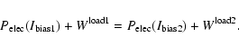 |
(22) |
By differencing the electrical power, we can calculated the
difference in optical power
 |
(23) |
We calculate the spectral normalization
from this power
difference. Table 3 shows the
spectral normalization and flat band optical efficiency calculated
from load curve differences.
The spectral calibration of the detectors allow us to compute
color corrections for all our photometric channels. In fact our
system is calibrated in flight using the CMB anisotropy as a
reference source (see Sect. 7.2.2). For this reason the
responsivity must be corrected when observing sources with a
different spectrum, like, e.g. interstellar dust emission.
However, the spectral matching of PSBs is good enough that even
not applying any color correction, the spurious polarization
degree is
 for any reasonable ISD
spectrum.
for any reasonable ISD
spectrum.
To characterize the polarization properties of our system, we
measured the polarization efficiency,
(or the cross-polar
response
), and the polarization angle of each
detector,
(see Eqs. (8) and (9)).
We made these measurements with the receiver alone and with the
whole system including the telescope.
Figure 11 shows the configuration of the receiver
polarization calibration. A rotating polarizing grid is placed
directly beneath the cryostat. It sits above a cold load (liquid
nitrogen) which is modulated by a chopper wheel. The chopper wheel
is rotated at 2 Hz and the grid has a rotation period of
approximately 10 min. When the transmission axis of the grid
is aligned with the polarization axis of the detector, the
detector sees whatever is behind the grid (i.e. the chopper wheel
or the cold load). When the grids are  out of alignment
the detector sees radiation reflected off the grid. The size of
the source aperture is such that the modulated signal fills
out of alignment
the detector sees radiation reflected off the grid. The size of
the source aperture is such that the modulated signal fills  of the receiver solid angle. The NDF was not in the beam,
in order to avoid multiple reflections, which could affect the
polarization response of the instrument. As a result, the
background on the detectors is about hundred times higher than in
flight, and the responsivity of all the detectors is many times
lower. This is not a problem for these measurements since, with
increased bias, there is plenty of signal anyway, and both the
polarization axis position and the cross-polar response are
independent of the absolute responsivity. Moreover, the modulated
signal is much smaller than the background, so that the the
response of the detectors, even if low, is still linear. The best
fit values of the cross-polar response parameter
when
the source is on the optical axis are reported in
Table 4. The measured cross-polar response is in
principle an upper limit for the cross-polar response of our
receiver, since it includes any cross-polar radiation produced by
the calibration source. However, using two identical polarizing
grids in series, we have verified that their transmission is <
of the receiver solid angle. The NDF was not in the beam,
in order to avoid multiple reflections, which could affect the
polarization response of the instrument. As a result, the
background on the detectors is about hundred times higher than in
flight, and the responsivity of all the detectors is many times
lower. This is not a problem for these measurements since, with
increased bias, there is plenty of signal anyway, and both the
polarization axis position and the cross-polar response are
independent of the absolute responsivity. Moreover, the modulated
signal is much smaller than the background, so that the the
response of the detectors, even if low, is still linear. The best
fit values of the cross-polar response parameter
when
the source is on the optical axis are reported in
Table 4. The measured cross-polar response is in
principle an upper limit for the cross-polar response of our
receiver, since it includes any cross-polar radiation produced by
the calibration source. However, using two identical polarizing
grids in series, we have verified that their transmission is < when the principal axes form an angle of
  .
We
conclude that the contribution of the source to the measured
cross-polar response is negligible. This fact is also confirmed
a posteriori by the low level of total cross polarization
measured in the 245 and 345 GHz detectors.
.
We
conclude that the contribution of the source to the measured
cross-polar response is negligible. This fact is also confirmed
a posteriori by the low level of total cross polarization
measured in the 245 and 345 GHz detectors.
![\begin{figure}
\par\includegraphics[angle=-90,width=6.8cm,clip]{3891f11a.eps}
\end{figure}](/articles/aa/full/2006/42/aa3891-05/Timg206.gif) |
Figure 11:
The source used for the polarization calibration of the
receiver. The system is tilted at
 so that rays
reflecting off the grid go to 300 K eccosorb absorbers (shown as
black, thick lines in the drawing). The aperture of the system is
5 cm. The chopper wheel chops between 77 K and 300 K, while
a belt drive rotates the polarizing grid. The chopper wheel
rotates at 2 Hz, while the grid has a rotation period of about 10 min.
so that rays
reflecting off the grid go to 300 K eccosorb absorbers (shown as
black, thick lines in the drawing). The aperture of the system is
5 cm. The chopper wheel chops between 77 K and 300 K, while
a belt drive rotates the polarizing grid. The chopper wheel
rotates at 2 Hz, while the grid has a rotation period of about 10 min. |
| Open with DEXTER |
Table 4:
Cross-polarization and principal axis angle measurements
for all the channels. The polarization angle and the beam filling
values refer to measurements on the complete instrument obtained
with the apparatus described in Fig. 12, while
the on-axis measurements refer to measurements on the receiver
alone, obtained with the apparatus described in Fig. 11 and also in a test cryostat testing single
channels.
![\begin{figure}
\par\includegraphics[width=7.6cm,clip]{3891f12a.eps}
\end{figure}](/articles/aa/full/2006/42/aa3891-05/Timg245.gif) |
Figure 12:
The apparatus for measuring polarization angle and cross
polar response of the entire telescope. The cold load is kept at
77 K by a liquid nitrogen bath. The source telescope is a 1.3 m off
axis paraboloid (the spare of the B03 mirror), and is kept at a
distance of 6 m from the B03 telescope. The source is
scanned in Azimuth by rotating the B03 payload around its vertical
axis. With a small diaphragm in the source, scans are repeated at
different elevations to obtain a full map of the beam and of its
polarization properties. With a large diaphragm, producing a
beam-filling beam, we change azimuth and elevation of B03 to find
the maximum signal. |
| Open with DEXTER |
For the measurement of the full system we used a fully polarized
modulated plane wave filling the telescope aperture. This was
produced using a thermal source in the focus of the spare BOOMERan G primary mirror. This inverted telescope system was placed in front
of the B03 telescope (see Fig. 12). Analytical
calculations (Dijk et al. 1974) and optical simulations show
that the cross-polar response introduced by the spare primary at
our frequency is  .
The source at the focus is made
with a high efficiency wire grid (12.5
diameter Tungsten
wires, 25
spacing) in front of a chopper alternating a 77 K
blackbody and a 300 K blackbody. The wire grid axis was tilted by
28
with respect to the optical axis of the system. Again, we
have verified using two identical grids in series, that their
transmission is <
when the principal axes form an angle
of .
We conclude that also in this case the contribution of
the source to the measured cross-polar response is negligible. The
B03 telescope was mounted on a rotating platform with absolute
encoders for angle measurements. The NDF was not in the beam, as
explained above. Bolometer data and the chopper reference signals
were read by the Data Acquisition System of the experiment. A
software demodulator measuring amplitude and phase of the
synchronous signal was used to extract the polarized source signal
from the background. Data were taken for 18 positions of the wire
grid between 0 and 180 degrees. After correcting for the tilt of
the grid with respect to the optical path, the data for all the
bolometers and for all the incidence angles were fit with Eq. (9).
.
The source at the focus is made
with a high efficiency wire grid (12.5
diameter Tungsten
wires, 25
spacing) in front of a chopper alternating a 77 K
blackbody and a 300 K blackbody. The wire grid axis was tilted by
28
with respect to the optical axis of the system. Again, we
have verified using two identical grids in series, that their
transmission is <
when the principal axes form an angle
of .
We conclude that also in this case the contribution of
the source to the measured cross-polar response is negligible. The
B03 telescope was mounted on a rotating platform with absolute
encoders for angle measurements. The NDF was not in the beam, as
explained above. Bolometer data and the chopper reference signals
were read by the Data Acquisition System of the experiment. A
software demodulator measuring amplitude and phase of the
synchronous signal was used to extract the polarized source signal
from the background. Data were taken for 18 positions of the wire
grid between 0 and 180 degrees. After correcting for the tilt of
the grid with respect to the optical path, the data for all the
bolometers and for all the incidence angles were fit with Eq. (9).
![\begin{figure}
\par\includegraphics[angle=0,width=4cm]{3891f13a.eps}\includegrap...
...4cm]{3891f13g.eps}\includegraphics[angle=0,width=4cm]{3891f13h.eps}
\end{figure}](/articles/aa/full/2006/42/aa3891-05/Timg247.gif) |
Figure 13:
Beam-integrated polarization response of the entire
instrument (PSB channels). |
| Open with DEXTER |
The measurement was carried out in two different configurations.
In the first we used a wide aperture on the cold source, so the
telescope beam was completely filled by a
 source. The
source-telescope relative position was then optimized for maximum
signal. In this configuration we measured the integrated
polarization properties of the instrument. The measured data for
this configuration are shown in Fig. 13 for the
PSB channels, and in Fig. 14 for the two-color
photometer channels. The data shown in Figs. 13 and 14 derive from measurements where we spent a long
(100 s) integration time in each input polarization angle.
As a result, the statistical error due to detector noise is
negligible with respect to calibration errors. In the plot of Figs. 13 and 14 the statistical
error is smaller than the dots representing the data. Inspection
of the same plots shows that there are in some cases random
deviations from the sine-wave behaviour otherwise evident in the
data, and that these deviations exceed the level allowed by the
statistical errors. These measurements have been carried out
during the pre-flight characterization of the instrument, and
there was no time to track-down the origin of the detected
deviations. We believe that they derive from perturbations of the
experimental setup due to the presence of other pre-flight
activities. However, treating these deviations as random errors,
and increasing the error bars accordingly so that the reduced
source. The
source-telescope relative position was then optimized for maximum
signal. In this configuration we measured the integrated
polarization properties of the instrument. The measured data for
this configuration are shown in Fig. 13 for the
PSB channels, and in Fig. 14 for the two-color
photometer channels. The data shown in Figs. 13 and 14 derive from measurements where we spent a long
(100 s) integration time in each input polarization angle.
As a result, the statistical error due to detector noise is
negligible with respect to calibration errors. In the plot of Figs. 13 and 14 the statistical
error is smaller than the dots representing the data. Inspection
of the same plots shows that there are in some cases random
deviations from the sine-wave behaviour otherwise evident in the
data, and that these deviations exceed the level allowed by the
statistical errors. These measurements have been carried out
during the pre-flight characterization of the instrument, and
there was no time to track-down the origin of the detected
deviations. We believe that they derive from perturbations of the
experimental setup due to the presence of other pre-flight
activities. However, treating these deviations as random errors,
and increasing the error bars accordingly so that the reduced  is 1, we find that the error in the best fit
cross-polarization is still <,
i.e. similar or lower than
the upper limit we have for the cross polarization of the source
itself. For this reason we have conservatively given a 2% error
for the cross-polarization measurements. This error includes the
statistical noise error, the systematic error, and the source
cross-polarization uncertainty.
is 1, we find that the error in the best fit
cross-polarization is still <,
i.e. similar or lower than
the upper limit we have for the cross polarization of the source
itself. For this reason we have conservatively given a 2% error
for the cross-polarization measurements. This error includes the
statistical noise error, the systematic error, and the source
cross-polarization uncertainty.
The best fit values of the parameters
and
are reported in Table 4. The
measured cross-polar response for the PSB channels is of the order
of 0.1. It is lower for the two color photometer channels, because
of the high efficiency of the wire grids. This fact confirms that
the source itself cannot contribute significantly to the measured
cross-polar response. In the second configuration we used a small
aperture ( FWHM), in order to investigate the
cross-polar response properties as a function of the off-axis
angle. In general the on-axis cross-polar response is lower than
the integral values of Table 4, while off-axis is
higher. This is in agreement with the physical optics model of our
system (shown in Fig. 7) and with the receiver
polarization calibration described above.
FWHM), in order to investigate the
cross-polar response properties as a function of the off-axis
angle. In general the on-axis cross-polar response is lower than
the integral values of Table 4, while off-axis is
higher. This is in agreement with the physical optics model of our
system (shown in Fig. 7) and with the receiver
polarization calibration described above.
![\begin{figure}
\par\includegraphics[angle=0,width=4cm]{3891f14a.eps}\includegrap...
...=4cm]{3891f14g.eps}\includegraphics[angle=0,width=4cm]{3891f14h.eps}\end{figure}](/articles/aa/full/2006/42/aa3891-05/Timg251.gif) |
Figure 14:
Beam-integrated polarization response of the entire
instrument (two-colors photometers). |
| Open with DEXTER |
We measured the beam profile
of our telescope
with a thermal source tethered on a balloon in the far field of
the telescope. The measurement was made in the relatively
transparent atmosphere of Antarctica. A small tethered balloon
lifted a microwave absorber (made out of eccosorb) into the
telescope beam, at a distance of about 1.5 km from the payload. We
used two sources to measure the beam, a sphere (with 45 cm
diameter) to measure the main beam, and a larger cylinder (with 76 cm diameter and 91 cm height) to map the sidelobes. The telescope
was steered by a combination of a slow azimuth scan with a very
slow elevation drift to map the beam profile of all the B03 detectors. The position of the source relative to the telescope
was continuously measured with the tracking star camera. This
system worked very well to measure 1D (azimuth) profiles of the
beam. However, due to the short suspension chain used in the
laboratory, the stability of the pointing system against
pendulations was not good, and we estimate an uncertainty of
in the elevation measurements. For this reason
we cannot estimate satisfactory 2D maps from the scans. We have
verified that the data fit our physical optics (BMAX) beam model
on single azimuth scans, as exemplified in Fig. 15,
where
 .
Similar results are obtained for many
cuts of our beam, obtained at different elevation (which is left
as a free parameter in the fits). So, even if we cannot measure
the 2D beam directly from the ground calibration data, we are
confident that we can use the beam computed from BMAX (plotted in
Fig. 6) to model it at the required accuracy level.
This is set by the presence of pointing jitter during the
observations (see Sect. 5.1), at a level of
.
Similar results are obtained for many
cuts of our beam, obtained at different elevation (which is left
as a free parameter in the fits). So, even if we cannot measure
the 2D beam directly from the ground calibration data, we are
confident that we can use the beam computed from BMAX (plotted in
Fig. 6) to model it at the required accuracy level.
This is set by the presence of pointing jitter during the
observations (see Sect. 5.1), at a level of  rms: in comparison, the small differences between the
data and the best fit are negligible.
rms: in comparison, the small differences between the
data and the best fit are negligible.
![\begin{figure}
\par\includegraphics[angle=90,width=7.2cm,clip]{3891f15a.eps}
\end{figure}](/articles/aa/full/2006/42/aa3891-05/Timg254.gif) |
Figure 15:
Measurement (crosses) of the azimuth beam profile of
channel 145W1, obtained from repeated scans of a thermal source in
the far field of the telescope. The measurements fit very well the
prediction of the physical optics code BMAX (dashed line). |
| Open with DEXTER |
From the BMAX beam we compute the transfer function
of
the instrument in multipole space. This is plotted in Fig. 16, where it is also compared to a Gaussian beam
transfer function. This
has been convolved with the
smearing resulting from pointing jitter, and used to deconvolve
all our power spectrum measurements, as reported in Jones et al. (2006a), Piacentini et al. (2006), Montroy et al. (2006).
![\begin{figure}
\par\includegraphics[angle=90,width=7.5cm,clip]{3891f16a.eps}
\end{figure}](/articles/aa/full/2006/42/aa3891-05/Timg255.gif) |
Figure 16:
Upper panel: instrument response at 145 GHz in multipole
space, computed from the BMAX physical optics model (red line).
The beam is similar to a 9.8 arcmin FWHM Gaussian (black line).
The ratio between the window function for the actual beam and that
for a Gaussian beam is plotted in the lower panel. |
| Open with DEXTER |
The instrument was launched by NASA-NSBF on Jan. 6, 2003, from
Williams Field, near the McMurdo Station, in Antarctica (167
5.760
E; 77
51.760
S). The flight lasted until Jan. 21,
with a total of 311 h.
The altitude of the payload during the flight is reported in Fig. 17. The periodic variation is due to the daily
change of elevation of the sun, while the long term trend is due
to a small leak in the balloon. We released ballast, in a moderate
amount on day 3, and then in a full drop on day 5. After day 11,
the altitude dropped below 28 km, telescope pointing become
difficult, and we had to stop observations.
![\begin{figure}
\par\includegraphics[angle=90,width=8.5cm,clip]{3891f17a.eps}
\end{figure}](/articles/aa/full/2006/42/aa3891-05/Timg256.gif) |
Figure 17:
Bottom: the altitude of the payload during the
balloon-flight. The sinusoidal variation is due to the daily
change of elevation of the sun, while the long term trend is due
to a small leak in the balloon. The arrows indicate ballast
releases used to counter the downward drift. Top: drift of
detector responsivity during the flight as measured with the
on-board calibration lamp: it is contained within a few % for the
whole length of the flight. The correlation with the altitude is
due to to the variation of atmospheric pressure with altitude,
which changes the temperature of the superfluid  bath in the
cryostat, with a consequent change in bolometer temperature.
bath in the
cryostat, with a consequent change in bolometer temperature. |
| Open with DEXTER |
We devoted a total of 119 h to scans on the deep survey
region, a total of 79 h to scans on the shallow survey region,
and a total of 30 h to scans over the Galactic plane. The
remaining hours have not been used for the data analysis, due to
spurious signals after events like ballast drop or elevation
changes, and due to testing, cryogenic operations, non optimal
performance of the attitude control system at the lowest
altitudes.
Maps of the sky coverage for the three surveys are reported in
Figs. 18 and 19. The
histogram of the integration time per pixel for the 3 different
regions is plotted in Fig. 20.
![\begin{figure}
\par\includegraphics[angle=90,width=7.3cm,clip]{3891f18a.eps}
\end{figure}](/articles/aa/full/2006/42/aa3891-05/Timg257.gif) |
Figure 18:
Map of the observation time (integral over all the 145
GHz bolometers) in the "Shallow'' and "Galaxy'' surveys of B03. The
larger box includes pixels of the shallow survey actually used for
the power spectrum analysis; the smaller box refers to the "Deep''
survey (see Fig. 19). |
| Open with DEXTER |
![\begin{figure}
\par\includegraphics[angle=90,width=7.8cm,clip]{3891f19a.eps}
\end{figure}](/articles/aa/full/2006/42/aa3891-05/Timg258.gif) |
Figure 19:
Map of the observation time (integral over all the 145 GHz bolometers) in the "Deep'' survey of B03. This region overlaps
completely with the central part of the shallow survey region. The
box includes pixels of the deep survey actually used for the power
spectrum analysis; however, the three circular regions marked
around strong AGNs have been excised. |
| Open with DEXTER |
![\begin{figure}
\par\includegraphics[angle=0,width=7cm,clip]{3891f20a.eps}
\end{figure}](/articles/aa/full/2006/42/aa3891-05/Timg259.gif) |
Figure 20:
Histogram of observation time per pixel (3.5 pixels) in the three surveys performed during the B03 flight. |
| Open with DEXTER |
Motion control was flawless in both the azimuth scanning and the
drive of the inner frame elevation when the payload was at nominal
altitude ( ). The GPS and FSS provided the required
coarse, 10 arcmin in-flight azimuth pointing and the
gyroscopes functioned almost continuously, aside from short
periods of dropouts or computer reboots. Near the end of the
flight, once the payload altitude dropped below 23 km, high
winds made motion control impossible and the ACS was shut down.
). The GPS and FSS provided the required
coarse, 10 arcmin in-flight azimuth pointing and the
gyroscopes functioned almost continuously, aside from short
periods of dropouts or computer reboots. Near the end of the
flight, once the payload altitude dropped below 23 km, high
winds made motion control impossible and the ACS was shut down.
Performance of the tracking sensors, the SC and the PSS, was
marred by communication problems in the ACS flight computer. With
both sensors operating at the same time the computer was unable to
parse the large amounts of incoming and outgoing data. To resolve
this issue the PSS was turned off early in the flight. The SC
provided the fine pointing data for the first and last thirds of
the flight. The cold temperature at low (pre-ballast drop)
altitude on day 4 caused the SC to freeze up, at which point the
PSS was turned back on, providing fine pointing for the middle
third of the flight.
5 Raw data processing
The polarization signal we are looking for is very small. In the
observations of the deep region at 145 GHz the contribution from
CMB polarization is of the order of a thousandth of the noise for
a single signal sample, and of the order of a tenth of the error
for the final measurement of a single 3.5 pixel. For this
reason we must properly exclude instrumental artifacts and avoid
the introduction of bias. We developed two completely independent
analysis pipelines, which will be called IT (Italy) and NA (North
America) in the following discussion. In this section and in the
following we outline the data analysis and specify where the two
pipelines make different choices. Despite the many differences,
the final spectra and maps are fully consistent. This is the best
test of the robustness of the dataset against alternative data
selection and analysis procedures.
The raw data acquired by the B03 telescope is convolved with a
transfer function consisting of the thermal response of the
detector and the filtering of the readout electronics. It also
contains transients caused by cosmic rays and our calibration
lamp, and longer time-scale events caused by thermal instabilities
resulting after each elevation change. At each step of the data
cleaning, we flag (mark as bad) some samples in the datastream and
fill these flagged samples with a constrained realization of the
noise. This noise filling uses linear prediction to replace
flagged samples based on the unflagged data on either side. After
removing very large cosmic rays, we flag a minimal number of
samples around each elevation change and fit out a decaying
exponential to the signal recovery.
Next, the datastreams are deconvolved with the combined thermal
and electrical transfer functions. For the NA pipeline, we used
transfer functions determined by pre-flight lab measurements
(described in Sect. 3.1). For the IT pipeline we
used the in-flight determination of the transfer function
described in Sect. 6.1.
The samples containing signals from our calibration lamp are
flagged. Medium amplitude cosmic rays are then flagged by passing
a simple template through the timestream and looking for spikes
larger than a certain size. The data is then heavily band-pass
filtered to make small cosmic rays more visible. A second
template is used to flag these small cosmic rays. This process
might mistake bright galactic sources for small cosmic rays. To
avoid this, we make a list of all bright source crossings in our
datastreams by using the coincidence of sources in both detectors
of a pixel pair. These samples are explicitly unflagged.
After building up a list of flagged samples, these samples are
filled with noise in the deconvolved data.
After completing this primary data cleaning, we found that each of
our time-streams contained an extraneous component that was well
correlated with the accelerations of the telescope's pitch and
roll gyroscopes. We fit these accelerations to the data in hour
long chunks and subtracted this contribution from the
time-streams.
5.1 Post-flight attitude determination
Pointing reconstruction consists of determining where each
detector was pointing in the sky at each data sample. We had a
redundant number of attitude sensors that can be combined
in different ways to obtain the final pointing solution. The
two pipelines are significantly different in this respect.
Pointing is described by the rotation matrix S that transforms
from the Celestial reference frame to the telescope reference
frame. In addition, the constant offsets of the pointing
directions of the horns in the telescope frame must be determined.
The problem is separated into two parts
 ,
where the
rotation matrix A converts from an Earth local reference frame
to the telescope frame, and B is the astronomical conversion. A is called the attitude matrix and is defined by three Euler
angles. It can also conveniently be described by a quaternion.
,
where the
rotation matrix A converts from an Earth local reference frame
to the telescope frame, and B is the astronomical conversion. A is called the attitude matrix and is defined by three Euler
angles. It can also conveniently be described by a quaternion.
To derive the attitude matrix we use several attitude sensors,
measuring either absolute angles or angular velocities. In our
case the absolute sensors are a differential GPS, a Stellar Sensor
and two Solar Sensors. The differential GPS can by itself measure
the attitude matrix A, but suffers for low frequency drifts, of
the order of 7
 .
The solar and the stellar
sensors measure the sensor-Sun or sensor-Star angles in the
payload frame, each providing two equations for the three unknown
Euler angles. Their combination thus provides a solvable system.
The angular velocities are obtained from the laser gyroscopes,
which have a bias due to their orientation in the Earth's magnetic
field.
.
The solar and the stellar
sensors measure the sensor-Sun or sensor-Star angles in the
payload frame, each providing two equations for the three unknown
Euler angles. Their combination thus provides a solvable system.
The angular velocities are obtained from the laser gyroscopes,
which have a bias due to their orientation in the Earth's magnetic
field.
We combine the signals of the different sensors taking into
account their noise/drift properties, by means of an optimized
Kalman filter (Kalman 1960) and by properly flagging
the sensors signals. The Kalman filter is based on the propagation
from the status at time t to the status at time
 as predicted by the dynamic measurements (from gyroscopes), in
combination with the direct measurements of the status
(update). The weighting of the update is given by the noise
properties of the gyroscopes and of the sensors.
as predicted by the dynamic measurements (from gyroscopes), in
combination with the direct measurements of the status
(update). The weighting of the update is given by the noise
properties of the gyroscopes and of the sensors.
The direction of lines of sight of the different detectors in the
telescope frame are derived from observation on known sources,
i.e. AGNs and Galactic HII regions.
A final correction to the IT pointing solution is obtained by
dividing the timestream in hour-long chunks. For each chunk we
make a sky map, and find the Azimuth and elevation offsets which
best fit a single template map derived from the BOOMERan G data from
the 1998 flight. An IRAS template was used for the scans on the
Galactic plane. The pointing solution is then corrected using
these best fit offsets, which are of the order of 1 arcmin.
The accuracy of the IT pointing solution is tested by means of
the signals detected in the direction of bright AGNs (see Sect. 6.2), and is of the order of
 rms.
rms.
Spikes in the raw pointing data are removed, and where possible
(over a few samples) the data can be linearly interpolated.
Post-flight re-calibrations are applied to the SC, PSS and FSS
data. For the SC/PSS azimuth and elevation this is a simple
matter of rotating the coordinates through a small angle until
correlated signal is minimized. The FSS is re-calibrated using
azimuth data from the GPS and the SC. A look-up table of sun
elevation versus raw FSS azimuth is constructed. Each element of
the table contains a GPS/SC derived sun azimuth relative to the
gondola, averaged over the whole flight. Raw FSS data is replaced
by the corresponding element in the table. Another useful derived
quantity is obtained from the GPS up, north and east velocity
data. The relatively stable LDB environment allows one to model
the gondola as a pendulum. With this model first estimates of
gondola pitch and roll,
pitchGV and rollGV may be
calculated from the GPS velocity data.
Clean, calibrated pointing fields are combined to determine the
gondola attitude. The sensors used in the final analysis include
the FSS azimuth, the SC elevation,
pitchGV, rollGV and
the integrated azimuth, pitch and roll gyro data. At frequencies
below 50 mHz the pointing solution is based on the best fit
azimuth, pitch and roll to the sun and star positions as
determined by the star camera, the FSS,
pitchGV and
rollGV. Gaps in the pointing data less than 40 s long are filled with integrated gyro data and above 50 mHz the pointing solution is strictly gyro signal. Gaps longer
than 40 s are flagged.
The elevation encoder signal is added to the gondola pitch,
thereby translating gondola (outer frame) attitude into telescope
(inner frame) attitude. The beam offsets for each detector are
obtained from fits to the five brightest QSOs in the CMB field.
Galactic and CMB source centroid offsets reveal a 0.1shift in gondola pitch after the mid-flight ballast drop. To
account for this approximately 6 h of data during and after
the ballast drop are flagged and a pitch shift is applied to all
pointing data preceding the drop. The reconstructed elevation and
azimuth of each beam on the sky, along with the measured
polarization angles for each detector, and the GPS latitude,
longitude and time are combined to determine the right ascension,
declination and the angle between the principal axis and the
meridian for each beam.
The CMB field pointing error, based on comparisons of analytical
beams with observed beams, is 2.5
rms in azimuth and
1.5
rms in elevation (see Sect. 6.2).
6.1 Transfer function
The transfer function of each detector, including the readout, has
been measured in flight using a procedure similar to the one
described in Crill et al. (2003). Even though the detectors
are designed to minimize cosmic rays cross section, each detector
produces detectable cosmic ray hits at the rate of about one every
two minutes, leaving on the data-stream a typical signature which
is the response of the system to an impulsive input. This
signature is the transfer function of the system in real space.
Of all the cosmic rays events in a given channel, only the subset
producing a spike in the (0.5-4) Volts range is selected for this
analysis, in order to neglect the effects of noise and to avoid
saturated events. Each event in the database is shifted in time
and normalized to minimize the chi square to a first order
approximation of the impulse response. The shift is performed on a
grid much finer than the 60 Hz sampling rate of the Data
Acquisition System. The combination of all the hits provides a
template of the impulsive response of each detector. As an
example, we plot in Fig. 21 the data for
detector 145W1. The result is insensitive to the choice of the
first order approximation. The Fourier transforms of those
templates are the transfer functions of the detectors. The method
is sensitive in a frequency range between 0.1 and 250 Hz. The resulting transfer function is similar (but not
exactly equal) to the one described in Sect. 3.1.
The small differences are probably due to the internal time
constant of the detector absorber, which affects in different ways
the response to mm-wave photons (depositing their energy on the
entire absorber) and the response to particles (depositing their
energy on a small localized part of the absorber). The IT pipeline
uses this transfer function, complementing it with lab calibration
data (Sect. 3.1) at
 .
The NA pipeline
uses the transfer function derived from pre-flight measurements.
.
The NA pipeline
uses the transfer function derived from pre-flight measurements.
![\begin{figure}
\par\includegraphics[width=7.1cm,clip]{3891f21a.eps}
\end{figure}](/articles/aa/full/2006/42/aa3891-05/Timg266.gif) |
Figure 21:
In-flight response of the 145W1 channel to an impulsive
event. The frequency response of the system is the Fourier
Transform of this response. The points are accumulated from
several cosmic-rays events shifted and normalized to fit the same
template. |
| Open with DEXTER |
6.2 Effective beam calibration
The effective B03 beam profiles are estimated combining physical
optics modeling and observations of bright extragalactic point
sources.
The physical beam is computed with a physical optics simulation of
the telescope (see Sect. 2.6 and Fig. 15); its shape is similar to a Gaussian function
with a FWHM of 9.8 arcmin for the 145 GHz channels and of
5.6
for the 245 and 345 GHz channels, with residuals of
the order of 2% (see Fig. 16).
Pointing errors produce a jitter on the map that we assumed to be
Gaussian and uniform in all the observed sky regions. Under this
assumption the jitter is defined by a single parameter,
 .
.
The observed profile of a point source is the convolution of the
physical beam with the Gaussian describing the pointing jitter.
For a Gaussian and isotropic physical beam we would have
![\begin{displaymath}B(\theta, \sigma_{\rm jitter}) = \exp \left[ - {{ \theta^2}\o...
...ma_{\rm beam}^2+ \sigma_{\rm jitter}^2\right) } } \right]\cdot
\end{displaymath}](/articles/aa/full/2006/42/aa3891-05/img268.gif) |
(24) |
Using the actual physical beam gives a result very similar to
Eq. (24). We measured
by
comparing the expected beam to the profiles of five sources
derived from the 8 PSBs maps at 145 GHz. We did not use the higher
frequency channels to estimate the jitter because of their higher
noise. The jitter, estimated as the weighted average of the 5 best
fit values, is
 arcmin. The FWHM
of the effective beam used in the final analysis is
arcmin. The FWHM
of the effective beam used in the final analysis is
 arcmin for the 145 GHz channels,
 arcmin for
the 245 and 345 GHz channels.
arcmin for
the 245 and 345 GHz channels.
6.3 Gain drift from calibration lamp
The responsivity of the bolometers depends on the operating
temperature and on the radiative loading. Both these quantities
can change during the flight.
For this reason, we include a calibration lamp in the cold optics
of BOOMERan G, that flashes every 15 min during the flight.
Details on the lamp, which is a composite bolometer structure
suspended in the center of a 1 cm hole in the tertiary mirror, are
in Crill et al. (2003). Its intrinsic stability depends on
the fact that the temperature achieved during the flashes is
significantly higher than the 2K base temperature. In this limit,
the emission of the lamp depends only on the heater current, which
is stable to better than .
The amplitude of the calibration signal changes only by a few
percent during the flight, as shown in the top panel of Fig. 17. To demonstrate that these fluctuations are not
intrinsic to the source, we have analyzed the DC signal across the
bolometers. This is proportional to the resistance of the
bolometers, which in turn is proportional to the responsivity. For
all the detectors we found a very good correlation between the
bolometer responsivity estimated from the calibration lamp and the
DC level: a clear indication that the signal of the calibration
lamp is constant through the flight.
6.4 Bolometer performance
We compute in-flight bolometer parameters with a bolometer model
based on Holmes et al. (1998), Jones (1953), and
Mather (1982) (see Jones 2005 for details).
The receiver model computes the total optical load on the
detectors using the resistance and thermal conductivity as
functions of temperature measured on the ground, and the in-flight
DC bolometer voltage, bias current, and noise.
We further model the optical load on the detectors
due to the atmosphere, telescope, and Cosmic Microwave Background,
and assume that leftover optical load is due to internal parasitic
loading. The optical load and responsivity change by several percent during
the flight (see Sect. 6.3) due to changes in emission
from the atmosphere and thermal radiation from cryostat
components.
We model the contributions to the noise from photon shot noise,
Johnson noise, phonon shot noise in the thermal link between the
bolometer and the cold stage, and amplifier noise and compute the
NEP (Noise Equivalent Power) contributed by each. The results of
these calculations, for typical values of the in-flight optical
load, are reported in Table 5.
Table 5:
The receiver
performance for a typical channel from each of the B OOMERANG bands,
computed from a receiver model using the observed average in-flight loading conditions.
The performance measured in flight is consistent with these estimates.
A source of impulsive noise is cosmic rays. All the B03 detectors
have been designed to minimize their cross section to cosmic rays.
As a result, even in the polar stratosphere, the average rate of
cosmic-rays hits in PSBs is one every two minutes. Over all the
identified events,  produce transients with amplitude at the
ADC
0.05< A < 1 V; 10
have amplitude 1V<A< 2V,
have
2V<A< 4V and
produce transients with amplitude at the
ADC
0.05< A < 1 V; 10
have amplitude 1V<A< 2V,
have
2V<A< 4V and  have A > 4V. All these events are flagged
and removed from the analysis as explained in Sect. 5.
have A > 4V. All these events are flagged
and removed from the analysis as explained in Sect. 5.
6.5 Noise estimation
The measurement of the actual in-flight noise is obtained via a
Fourier transform of the raw datastream. A sample power spectrum
of the raw data (deconvolved from system frequency response, as
estimated in Sects. 3.1 and 6.1) is shown in Fig. 22. Signal
contributions are present above the noise, at the scan frequency
and at its harmonics, and in the 0.1 Hz range. The
Generalized Least Squares (GLS) map-making method relies on
knowledge of the noise correlation function, which is related to
the noise power spectral density by a Fourier transform. This
quantity must be estimated from the data themselves, which are a
combination of noise and signal.
The standard way to characterise the underlying noise is by
subtracting an estimate for the signal (see Ferreira & Jaffe
2000). Since the signal can be estimated by making a
map, the two problems are entangled, and a possible approach is
iterative (see Prunet et al. 2001 and Dore et al. 2001; see however Natoli et al. 2002 for an
alternative approach).
In the IT pipeline, a rough estimate of the signal is obtained by
naïvely coadding a band-pass filtered version of the timeline;
the resulting map is used as a baseline to obtain an estimate of
the noise power spectral density. This is in turn used to make a
new, GLS, map and the process can be iterated as desired. We have
found empirically that, for B03, no significant improvement is
obtained by iterating more than five times. Furthermore, tests on
simulated data suggest that, under these conditions, the
underlying noise properties are recovered without any substantial
bias (see De Gasperis et al. 2005).
The following scheme is employed to optimally use the information
produced by all detectors. The above procedure is repeated for
each uncalibrated bolometer timeline (e.g. eight times, one for
each 145 GHz bolometer). Then, a first estimate of the relative
calibration factors between channels at a given frequency are
computed as explained in Sect. 7.2.1. A multi-channel,
high signal to noise ratio, relatively calibrated map is produced
and used as an estimate for the underlying signal to evaluate a
more precise noise power spectral density for each bolometer. As a
further step, relative calibration factors are recomputed with
these noise estimates, and a new multichannel map is made. We
have verified that iterating further is useless since if this last
map is used to produce further noise estimates, the latter do not
change significantly.
A sample noise power spectrum is shown in Fig. 22. With
this method we estimate the noise of all the B03 channels in
 .
This is converted into NEP (see Table 6) using the measured in-flight responsivity (see Sects. 7.2.1 and 7.2.2).
.
This is converted into NEP (see Table 6) using the measured in-flight responsivity (see Sects. 7.2.1 and 7.2.2).
![\begin{figure}
\par\includegraphics[width=7.7cm,clip]{3891f22a.eps}
\end{figure}](/articles/aa/full/2006/42/aa3891-05/Timg288.gif) |
Figure 22:
Flight-average of the auto power spectrum of the data
time-stream, from channel 145W1 (top line, red). The data are
recorded at the ADC input. The total gain of the readout chain
between the bolometer and the ADC input is 50 000. The middle line
(black) is the auto power spectrum of the time stream after
subtraction of the signal estimated from the best fit map: this is
an estimate of the instrumental noise. Comparing the two, it is
evident that most of the CMB signal is encoded in the 0.05-1 Hz
range. The lowest line (blue) is the cross correlation of the
noise (time-stream - best fit map) signal from 145W1 and 145W2. In
the frequency range of interest for the CMB signal, the
cross-correlated noise signal is at least one order of magnitude
smaller than the auto-correlated signal. The correlated noise
rises at very low frequencies, where atmospheric effects, thermal
drifts, pendulations and scan-related microphonics can be present.
At frequencies higher then 2 Hz the noise correlation remains well
below the noise of the detector. |
| Open with DEXTER |
Table 6:
In flight detectors performance: we report the
noise equivalent temperature at 1 Hz, derived from the noise
equivalent voltage measured in flight as in Sect. 6.4, from the responsivity estimated as in Sect. 7.2.1 and from the spectral calibrations of Sect. 3.2. In our survey, this frequency corresponds to
multipoles
 .
The noise increases at
lower and at higher frequencies, as shown in Fig. 22.
.
The noise increases at
lower and at higher frequencies, as shown in Fig. 22.
There is a component of noise correlated between different
detectors. This is especially visible at very low frequencies. In
Fig. 22 we include an example. This noise has a similar
level for all detector couples (roughly independent of whether the
detectors are members of the same PSB pair). It may originate in
scan synchronous microphonics and in fluctuations of the residual
atmosphere. The levels of correlated noise in the interesting
frequency band (0.1-2 Hz), for all possible couples of 145 GHz
bolometers, are compared to the levels of noise of each bolometer
in Table 7. The presence of this correlated noise
is neglected in the map-making, but is taken into account for our
estimates of the power spectra (see Jones et al. 2006a;
Piacentini et al. 2006; Montroy et al. 2006).
Table 7:
Absolute value of the noise cross-power-spectrum for the
145 GHz detectors, averaged in the 0.1-2 Hz range. The numerical
values have been normalized to the noise auto-power-spectrum of
detector 145W1, which is
 at the ADC
input.
at the ADC
input.
The dipole of the CMB is visible as an approximately linear drift
along our short scans. It produces a scan-synchronous triangle
wave (see Fig. 23) that we have removed from the
time-streams before proceeding with the analysis. Since it is
scan-synchronous, as some possible systematics, we cannot use it
for a precise calibration of the instrument: the calibration
accuracy achievable with the dipole is  ,
not
sufficient for our purposes. However, its amplitude is consistent
with the amplitude of the CMB Dipole measured by COBE and WMAP.
,
not
sufficient for our purposes. However, its amplitude is consistent
with the amplitude of the CMB Dipole measured by COBE and WMAP.
![\begin{figure}
\par\includegraphics[angle=90,width=7.6cm,clip]{3891f23a.eps}
\end{figure}](/articles/aa/full/2006/42/aa3891-05/Timg291.gif) |
Figure 23:
Raw-data time-stream from channel 145W1. It is evident
the scan-synchronous signal from the CMB dipole. The (red) line is
the CMB dipole, measaured by WMAP and COBE, along this scan. There
is clear agreement between the predicted CMB dipole and the
observed scan synchronous signal. |
| Open with DEXTER |
7.1 The map making pipeline
A Generalized Least Square (GLS) method is used to jointly
estimate the Stokes parameter sky maps I, Q and U from time
ordered data. The best maps are obtained by combining data from
all detectors available at a given frequency. This approach is
implemented in the ROMA map making code (De Gasperis et al. 2005) for the IT pipeline, and in the DIQU code
(Jones et al. 2006b) for the NA pipeline. Following Eq. (10), we assume the following data model:
![\begin{displaymath}\mathcal D_{t}^i = \frac{{\cal S}^{i}}{2}
A_{tp}^i \left[I_p...
...pha_{t}^i + U_p \sin~ 2\alpha_{t}^i \right)
\right] + n_{t}^i.
\end{displaymath}](/articles/aa/full/2006/42/aa3891-05/img292.gif) |
(25) |
Here i, t and p label channel, time and map pixel
respectively; Dti are the time ordered data for a given
channel, related to the sky maps Ip, Qp and Up by the
pointing operator Atpi, which we assume to be as simple as
possible: its elements are equal to one when a pixel is observed,
and are zero otherwise. Equation (25) can be recast in a
more compact formalism by defining a generalized pointing matrix
Atp which includes the trigonometric functions and a
map triplet
 :
:
 |
(26) |
The GLS estimator for
Sp is then (see De Gasperis et al. 2005)
 |
(27) |
where
N is the noise covariance matrix, whose
estimation is discussed in Sect. 6.5 above:
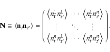 |
(28) |
This matrix becomes block diagonal assuming that there is no noise
correlation between different detectors:
 |
(29) |
Given the size of the problem, in the IT pipeline the map making
normal Eq. (27) are solved by implementing
a Fourier-based preconditioned conjugate gradient iterative
solver, which only needs to perform matrix to vector products.
This approach critically depends on the assumption that the noise
is stationary (Natoli et al. 2001). In the NA pipeline a
Jacobi solver is used.
In practice, there are many further details. Since the solver
works in Fourier space, the timeline must be continuous;
bad or missing data chunks ("gaps'') are
replaced by a constrained realization of Gaussian noise (Hoffman
& Ribak 1991), designed to mimic the correct noise
behavior at the gap's boundaries. The samples belonging to these
chunks are then flagged and the solver is instructed not to take
them into account, as they do not contain any useful data. The
noise correlation functions (also called noise filters) are band
pass filtered in the range
70 mHz-14.5 Hz before being
given to the map making code.
Each detector has its own noise filter, which is kept constant
over the full flight (i.e. data are reduced as if the noise were
stationary within a single detector) for the IT pipeline, while the NA
pipeline estimates noise separately for each (hour long) chunk of
data. The NA approach treats the non stationarity of the
data, at the cost of a reduced accuracy in the estimate of the
noise filter. The differences in the resulting maps are
negligible.
For the polarization maps, detectors forming PSB pairs are treated
as independent detectors in the IT pipeline, while the difference
of their signals is used by the NA pipeline (see Jones et al. 2006b, for details).
The ROMA code employs about 20 min (and 200 iterations)
to produce a set of I, Q, U maps from an eight bolometer
(full flight) timeline, when running a 128 processor job on an IBM
SP machine featuring 450 MHz Power 3 processors.
The first step in obtaining our final product maps of I, Q, U, is
the relative calibration of all the detectors. As explained in Sect. 2.1, we need a relative calibration accuracy of
the order of  .
We start by producing single detector
maps of I using one of the map-making procedures. We then proceed
in two ways: in pixel space and in multipole space.
.
We start by producing single detector
maps of I using one of the map-making procedures. We then proceed
in two ways: in pixel space and in multipole space.
7.2.1 Relative calibration from pixel-pixel correlation of
different PSBs
We carry out this analysis for the PSBs in the deep region. We
use the 145 GHz W1 channel as the reference channel. The
characteristics of these channels (beam, frequency response,
noise, polarization efficiency) are so similar that their data can
be directly compared, pixel to pixel. For channel j we scatter
plot the Ii,j values (where i is the pixel index) versus
the Ii,W1 values, and we fit the data to a straight line. We
estimate the error on each Ii,j as
 where
where  is obtained by integrating the TOD noise power
spectrum, and Nj,i is the number of observations of pixel i. The slope of the best fit line is the relative calibration
factor
is obtained by integrating the TOD noise power
spectrum, and Nj,i is the number of observations of pixel i. The slope of the best fit line is the relative calibration
factor
 .
Simulations show that this procedure
results in an accurate (within 1%) estimate of the relative
calibration. The results for all channels are reported in Table 8.
.
Simulations show that this procedure
results in an accurate (within 1%) estimate of the relative
calibration. The results for all channels are reported in Table 8.
Table 8:
Relative calibration
 of the PSB channels
obtained from the pixel-pixel scatter plots with NSIDE = 256 (second
column, see Sect. 7.2.1) and from the cross-spectrum
(third column, see Sect. 7.2.2), using W1 as the
reference channel. For
of the PSB channels
obtained from the pixel-pixel scatter plots with NSIDE = 256 (second
column, see Sect. 7.2.1) and from the cross-spectrum
(third column, see Sect. 7.2.2), using W1 as the
reference channel. For
 ,
1-errors are used. For
,
1-errors are used. For
 ,
we also include
in the error the possible bias due to a conservative
,
we also include
in the error the possible bias due to a conservative 
 error in the estimate of the noise.
We also study the effect of a mis-estimate of the noise in the
responsivity estimate. This depends strongly on the signal to
noise per pixel of the data. For 7
pixels, the signal to
noise per pixel for CMB anisotropies is 3. In these
conditions, simple simulations show that in order to bias the
relative calibration by more than
the estimate of the noise
must be wrong by more than .
We conclude that this method
provides a robust estimate of the relative calibration. The errors
on the relative calibration results reported in Table 8 include the effect of a conservative 20%
misestimate of the errors per pixel.
If, instead, the S/N per pixel is 1, then a misestimate of the noise induces
errors in the
calibration. This happens when an absolute calibration is
attempted by fitting Ii,j versus the
 .
Since the
angular resolution of WMAP is worse than the one of B03, and the
noise per pixel is higher, the slope of the best fit line is
significantly biased. Also, working in pixel space it is not
trivial to take into account the difference in beam size and shape
between B03 and WMAP.
.
Since the
angular resolution of WMAP is worse than the one of B03, and the
noise per pixel is higher, the slope of the best fit line is
significantly biased. Also, working in pixel space it is not
trivial to take into account the difference in beam size and shape
between B03 and WMAP.
7.2.2 Absolute and relative calibration from ratios of
cross-spectra
We can compare the signals detected by different detectors
observing the same sky in multipole space rather than in pixel
space. A cross-power spectrum is very useful in this case, due to
its unbiased nature: the noise properties of the two signals do
not affect the results. Moreover, the use of the cross-power
spectrum allows us to properly take into account in a simple way
the effect of the different angular resolution, and map-making
transfer functions. All these effects can be included in a
function  ,
which can be different for each channel k.
Since we do see CMB fluctuations in all the B03 maps, this method
can be used to calibrate the B03 detectors at 145, 245 and 345 GHz, and to find the absolute calibration factor by comparing B03 maps to a reference map from WMAP.
,
which can be different for each channel k.
Since we do see CMB fluctuations in all the B03 maps, this method
can be used to calibrate the B03 detectors at 145, 245 and 345 GHz, and to find the absolute calibration factor by comparing B03 maps to a reference map from WMAP.
We expand the uncalibrated maps of all channels in spherical
harmonics:
 |
(30) |
We can compute the cross power spectrum
 and compare it to
the cross power spectrum
and compare it to
the cross power spectrum
 :
the ratio is the relative
calibration of channel k against the reference channel W1 of B03:
:
the ratio is the relative
calibration of channel k against the reference channel W1 of B03:
 |
(31) |
This is iterated for all  for consistency checks. This
procedure needs Monte-Carlo simulations to properly take into
account any correlated noise between B03 channels i and j.
for consistency checks. This
procedure needs Monte-Carlo simulations to properly take into
account any correlated noise between B03 channels i and j.
To avoid this, we can use non- B03 datasets (the V and W WMAP maps
and the 150 GHz B98 map, denoted by greek indices) as pivot
signals:
 |
(32) |
To improve the accuracy, we also use slightly more complex
combinations of signals:
 |
(33) |
and average all the multipole bins between  and
and
 .
Using Eqs. (32) and (33) we
have obtained 21 estimates of the relative calibration for each
B03 channel. We have computed the weighted average of these
estimates, and checked with Monte-Carlo simulations that such
procedure is accurate and that the standard error on the weighted
average is a correct estimate of the statistical uncertainty. The
results are reported in Table 8. These
relative calibrations are consistent with the pixel-space ones
obtained in Sect. 7.2.1, and the statistical
uncertainty is smaller, ranging between
.
Using Eqs. (32) and (33) we
have obtained 21 estimates of the relative calibration for each
B03 channel. We have computed the weighted average of these
estimates, and checked with Monte-Carlo simulations that such
procedure is accurate and that the standard error on the weighted
average is a correct estimate of the statistical uncertainty. The
results are reported in Table 8. These
relative calibrations are consistent with the pixel-space ones
obtained in Sect. 7.2.1, and the statistical
uncertainty is smaller, ranging between  and
and  .
We have also verified that using either of the two sets of
relative calibrations does not change the combined map
significantly.
.
We have also verified that using either of the two sets of
relative calibrations does not change the combined map
significantly.
Having measured the relative calibrations for all channels of the
same band, we can combine them into an uncalibrated optimal map
of the sky, using the optimal map-making described in Sect. 7.1.
We then estimate the absolute calibration of this map by comparing
it to the WMAP map in the same region. The WMAP all-sky maps are
calibrated with remarkable accuracy (0.5%, see Bennett et al. 2003). So we can compare the angular power spectra
measured by B03 and WMAP in the same sky region in order to
measure the absolute responsivity
of B03.
Assuming that the uncalibrated signal in B03 (in Volt) is related
to the CMB temperature measured by WMAP as
 ,
we can estimate
from different
combination of B03 and WMAP power spectra. We use the following
one:
,
we can estimate
from different
combination of B03 and WMAP power spectra. We use the following
one:
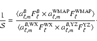 |
(34) |
For the 145 GHz PSBs, we compute the cross-power spectrum of
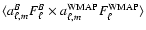 using optimal combined maps of all channels
for both the experiments, and the cross-power spectrum of
using optimal combined maps of all channels
for both the experiments, and the cross-power spectrum of
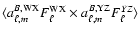 using optimal maps obtained combining the Wand X PSBs for the first map, and the Y and Z PSBs for the
second one. Using this denominator in place of
using optimal maps obtained combining the Wand X PSBs for the first map, and the Y and Z PSBs for the
second one. Using this denominator in place of
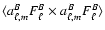 we avoid the need to remove a bias due to correlated noise. This
choice, based on half of the detectors, does not degrade the
precision of the result, which is already limited by WMAP noise.
we avoid the need to remove a bias due to correlated noise. This
choice, based on half of the detectors, does not degrade the
precision of the result, which is already limited by WMAP noise.
For the 145 GHz T map, we show in Fig. 24 the
measurement of
obtained from Eq. (34),
i.e. the absolute calibration factor as a function of .
The
error bars are estimated with a bootstrap method (see Polenta
2004 for details). Its flatness confirms that we are
properly correcting for beam, pixelization and noise effects.
![\begin{figure}
\par\includegraphics[width=7.6cm,clip]{3891f24a.eps}
\end{figure}](/articles/aa/full/2006/42/aa3891-05/Timg331.gif) |
Figure 24:
Absolute calibration factors
 based
on WMAP measurement. The cross-power spectra are computed using
the shallow integration region with uniform weight. The final
value for
is the weighted average of the
.
based
on WMAP measurement. The cross-power spectra are computed using
the shallow integration region with uniform weight. The final
value for
is the weighted average of the
. |
| Open with DEXTER |
Table 9:
Summary of the different choices made for the two
data analysis pipelines.
We confirm the robustness of the result by computing calibration
factors from the shallow and deep surveys separately and by
applying different weighting schemes. The final result for the 145 GHz map is
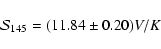 |
(35) |
where the 1-
error already incorporates
the effect of the calibration uncertainty of WMAP. The absolute
responsivity of a single channel k can be obtained from the
values listed in Table 8 as
 .
.
The calibrations of 245 and 345 GHz maps are found in a similar
way. We obtain
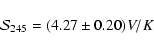 |
(36) |
and
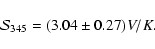 |
(37) |
![\begin{figure}
\par\includegraphics[angle=0,width=5cm]{3891f25aCMJN.eps}\include...
...1f25eCMJN.eps}\includegraphics[angle=0,width=5cm]{3891f25fCMJN.eps}
\end{figure}](/articles/aa/full/2006/42/aa3891-05/Timg336.gif) |
Figure 25:
B03 survey of the Galactic plane. In the top row we
display ( left to right): B03 maps at 145, 245 and 345 GHz. The
brightness units are MJy/sr. The conversion factors from MJy/sr to
 are given in Table 3. In
the bottom row we report, for comparison, maps of the same region
from ( left to right): the CO survey of Dame et al. (2001), the
WMAP 94 GHz channel, and the IRAS 3000 GHz survey. All the maps
have been convolved with a 6
FWHM Gaussian filter. The
equivalent FWHM resolution of the maps is indicated by the yellow
circle on the bottom right of each panel. The hexagons locate
RCW38 (
are given in Table 3. In
the bottom row we report, for comparison, maps of the same region
from ( left to right): the CO survey of Dame et al. (2001), the
WMAP 94 GHz channel, and the IRAS 3000 GHz survey. All the maps
have been convolved with a 6
FWHM Gaussian filter. The
equivalent FWHM resolution of the maps is indicated by the yellow
circle on the bottom right of each panel. The hexagons locate
RCW38 (
 )
and IRAS 08576 ( )
and IRAS 08576 (
 ). ). |
| Open with DEXTER |
7.3 Differences in the two pipelines
Before discussing the results of the analysis, we summarize in
Table 9 the most important differences between
the two pipelines. Despite the many different choices, the final
results of the analysis are very consistent for both the maps (see
Sect. 7.4 and following) and the power spectra (Jones
et al. 2006a; Piacentini et al. 2006; Montroy
et al. 2006).
![\begin{figure}
\par\includegraphics[width=7.3cm,clip]{3891f26a.eps}\par\vspace*{...
...}\par\vspace*{3mm}
\includegraphics[width=7.3cm,clip]{3891f26c.eps}
\end{figure}](/articles/aa/full/2006/42/aa3891-05/Timg337.gif) |
Figure 26:
Measured integrated fluxes for selected Galactic sources
observed by B03 (diamonds). The other data points are from WMAP
(stars), from DIRBE (triangle) and from the IRAS/DIRBE map
(square). The continuous line is the best fit SFD obtained as the
sum of a power law at low frequencies ( )
plus a
thermal dust spectrum dominating at high frequencies ( )
plus a
thermal dust spectrum dominating at high frequencies (
 ). ). |
| Open with DEXTER |
7.4 Observations of the galactic plane
Brightness maps of a section of the Galactic plane at 145, 245 and
345 GHz are shown in Fig. 25, in comparison with
other relevant maps of emission from dust and associated molecular
gas. Several known HII regions are evident in the maps.
Particulary luminous are RCW38 (at RA = 134.76,
Dec = -47.47)
and IRAS 08576 (at RA = 134.92,
Dec = -43.75). Diffuse emission
is also evident. It is instructive to compare the B03 maps to
monitors of different components of the ISM, like the IRAS/DIRBE
maps for the dust continuum and the 115 GHz CO map of Dame et al. (2001) for the molecular gas (see bottom row of
Fig. 25). There is a good correlation between the B03 maps and the IRAS/DIRBE 3000 GHz map for most of the diffuse
structure observed. A striking exception is the cloud evident in
all B03 channels at RA = 135.24
and Dec = -44.80:
this is very
dim in the IRAS map, while it is bright in the CO map and is also
visible in the WMAP 94 GHz map: the signature of a cold dust cloud
associated with molecular gas.
The measured spectral flux density (SFD) of the main Galactic
sources measured by B03 is reported in Fig. 26.
The fluxes have been obtained integrating the brightness maps on
disks centered on the sources. The diameter of the disks is chosen
as the maximum between the apparent size of the source and twice
the FWHM of the experiment beam. The error in the determination of
the flux is dominated by the presence of diffuse emission, which
must be subtracted to estimate the net flux of the source: this is
less critical for RCW38, which is a relatively isolated source.
This results in error bars larger than those from calibration and
pointing jitter.
In order to gain insight on the physical processes of emission
operating in the sources, we combined the B03 SFD data with data
from WMAP, DIRBE and IRAS (see Fig. 26). A
combination of a power law dominating at low frequencies (), and a dust-spectrum at high frequencies (
)
produces a good fit to the data.
We find dust temperatures of
 ,
,
 ,
and
,
and
 for RCW38, IRAS 08576, and the CO cloud
respectively. The spectral index of the power law is
for RCW38, IRAS 08576, and the CO cloud
respectively. The spectral index of the power law is
 ,
,
 ,
and
,
and
 for RCW38,
IRAS 08576, and the CO cloud respectively.
for RCW38,
IRAS 08576, and the CO cloud respectively.
A word of caution is necessary for the power-lax indices derived
here. We are using data from experiments with different angular
resolution. In particular the low frequency data have poorer
angular resolution, so the measured flux can be contaminated by
nearby sources entering these wider beams. For this reason the
spectra shown in Fig. 26 could be increasingly
contaminated (biased high) at low frequencies. This issue will be
analyzed in a future publication.
The S/N ratio of the observations of RCW38 is high enough that we
can also give an upper limit for the ellipticity of our beam. We
fitted the 145 GHz map of RCW38 with an elliptic Gaussian, leaving
as free parameters the two FWHMs, the orientation angle, and the
amplitude. The beam FWHMs we find are consistent with the ones
discussed in Sect. 6.2. The measured ellipticity is
 .
This includes the effects of beam ellipticity,
anisotropic pointing jitter and intrinsic source ellipticity. The
cross-link of the sky scans (see Sect. 2.2) is such
that the effect of an elliptic beam could not cancel out. It is
thus unlikely that the beam ellipticity is >;
according to
the analysis carried out in Sect. 2.6, the
contamination of our polarization measurements due to beam
ellipticity is thus expected to be less than a few %.
.
This includes the effects of beam ellipticity,
anisotropic pointing jitter and intrinsic source ellipticity. The
cross-link of the sky scans (see Sect. 2.2) is such
that the effect of an elliptic beam could not cancel out. It is
thus unlikely that the beam ellipticity is >;
according to
the analysis carried out in Sect. 2.6, the
contamination of our polarization measurements due to beam
ellipticity is thus expected to be less than a few %.
RCW38 is the brightest source we observed. At 145 GHz the
polarization of RCW38 is very low. We have carried out an analysis
on the 145 GHz W, X, and Y PSBs, analyzing 53 scans over the
source, and assuming that there is a constant polarization over
the size of the source. For each scan and for each of the 6 bolometers we fit a maximum amplitude of the detected signal. We
then solve for Q and U of each scan using the detector signal
differences W1-W2, X1-X2, Y1-Y2, taking into account the relative
calibration of the bolometers, the color corrections, and the
orientation angles. The resulting average values for Q and Uare
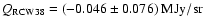 and
and
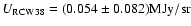 .
Since the average brightness for RCW38 on the
same scans is 3.7 MJy/sr, the upper limit for the polarization
degree is
.
Since the average brightness for RCW38 on the
same scans is 3.7 MJy/sr, the upper limit for the polarization
degree is
 (2- U.L.).
7.5.1 Maps of CMB temperature anisotropy at high galactic
latitude
The main product of this experiment is the 145 GHz map, which is
shown as a large image in Fig. 27. The structure
visible in the map with high S/N is CMB anisotropy. ISD is
negligible in comparison to the CMB, as obtained in B98 (Masi
et al. 2001) and as we confirm below with the B03 data.
Maps of the shallow and deep regions at 145, 245 and 345 GHz are
compared in Figs. 28 and 29
respectively. For a meaningful comparison, all maps have been
filtered in the same way. Aggressive high-pass filtering of the
time ordered data (cut-on at 7.5 times the scan frequency) was
required for the 245 GHz and 345 GHz bolometers, in order to avoid
artifacts due to scan synchronous noise. The brightness at 245 and 345 is due to a mixture of CMB and emission from interstellar dust
(ISD), as evident from the comparison of the CMB-subtracted maps
to the IRAS 3000 GHz map in the botton rows of Fig. 28.
![\begin{figure}
\par\includegraphics[angle=0,width=5.3cm,clip]{3891f28aCMJN.eps}\...
...N.eps}\includegraphics[angle=0,width=5.3cm,clip]{3891f28fCMJN.eps}
\end{figure}](/articles/aa/full/2006/42/aa3891-05/Timg349.gif) |
Figure 28:
The shallow and deep surveys of B03.
Top row: I maps from B03. From left to right: 145 GHz; 245 GHz;
345 GHz. I is encoded in the false color scale in thermodynamic
temperature units for a 2.725 K blackbody. The pixel size is 3.4 arcmin. Bottom row, from left to right: IRAS/DIRBE image of the
same region at 3000 GHz; B03 difference map obtained by
subtracting the 145 GHz map from the 245 GHz map, in order to
remove CMB anisotropy from the resulting map; B03 difference map
obtained as 345 GHz map minus 145 GHz map. The central region,
where the noise is evidently lower, is the deep survey. In Fig. 29 we zoom on such region. The circles label the
positions of known AGNs. To remove large-scale gradients, a
high-pass filter at 7.5 times the scan frequency was applied on
the time-ordered data: this filter is needed to remove artifacts
due to scan synchronous noise in the 245 and 345 GHz maps. A
Gaussian filter with 7
FWHM was used as anti-aliasing. |
| Open with DEXTER |
![\begin{figure}
\par\includegraphics[height=4.7cm,width=5.2cm,clip]{3891f29aCMJN....
...eps}\includegraphics[height=4.7cm,width=5cm,clip]{3891f29fCMJN.eps}
\end{figure}](/articles/aa/full/2006/42/aa3891-05/Timg350.gif) |
Figure 29:
The deep survey of B03. Top row: I maps from B03.
From left to right: 145 GHz; 245 GHz; 345 GHz. I is encoded in the
false color scale in thermodynamic temperature units for a 2.725K
blackbody. The pixel size is 3.4 arcmin. Bottom row, from left to
right: IRAS/DIRBE image of the same region at 3000 GHz; B03 difference map obtained by subtracting the 145 GHz map from the
245 GHz map, in order to remove CMB anisotropy from the resulting
map; B03 difference map obtained as 345 GHz map minus 145 GHz map.
All the maps have been filtered in the same way. To remove
large-scale gradients, a high-pass filter at 7.5 times the scan
frequency was applied on the time-ordered data: this filter is
needed to remove artifacts due to scan synchronous noise in the 245 and 345 GHz maps. A Gaussian filter with 7
FWHM was
used as anti-aliasing. |
| Open with DEXTER |
The temperature anisotropy of the CMB is measured with high S/N in
the deep 145 GHz map. Figure 30 compares the 145 GHz
deep map with maps of the same region obtained from BOOMERan G-98 at
150 GHz, and from WMAP at at 94 GHz. There is excellent
morphological agreement between all three maps.
To estimate more precisely the S/N of the 145 GHz deep map, we
jackknife the data to provide two independent maps: one using data
only from the first half of the deep survey (D1) and one using
data only from the second half of the deep survey (D2). We then
form the sum and difference maps, (D1+D2)/2 and (D1-D2)/2. The sum
map contains both signal and noise, the difference map only noise.
For all maps we have used HEALPIX NSIDE = 1024, i.e. a pixel side of
3.5.
Histograms of both maps, shown in Fig. 31, are
Gaussian-distributed. The rms in the sum and difference maps is
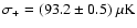 and
and
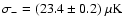 ,
respectively. The rms of the sky signal is thus
,
respectively. The rms of the sky signal is thus
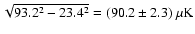 ,
where the error now
includes the uncertainty in absolute calibration. Realistic
simulations of our observations, including all the details of scan
speed, coverage, detectors noise, filtering, pixelization, etc.
can be used to estimate the expected rms of CMB anisotropy in
these observations, for the standard "concordance'' model best
fitting WMAP. We used the same simulations used for our spectral
analysis (Jones et al. 2006a; Piacentini et al. 2006; Montroy et al. 2006). The result is
,
where the error now
includes the uncertainty in absolute calibration. Realistic
simulations of our observations, including all the details of scan
speed, coverage, detectors noise, filtering, pixelization, etc.
can be used to estimate the expected rms of CMB anisotropy in
these observations, for the standard "concordance'' model best
fitting WMAP. We used the same simulations used for our spectral
analysis (Jones et al. 2006a; Piacentini et al. 2006; Montroy et al. 2006). The result is
 (including cosmic variance). A similar result
is obtained integrating the power spectrum of the "concordance''
model over the B03 window function shown in Fig. 16.
(including cosmic variance). A similar result
is obtained integrating the power spectrum of the "concordance''
model over the B03 window function shown in Fig. 16.
The distribution of the measured brightness in the deep 145 GHz
map is accurately Gaussian. The simplest Gaussianity test is the
evaluation of the skewness S3 and kurtosis S4 of the pixel
temperature distribution, computed as
![\begin{displaymath}S_3= {1 \over N} \sum_{i=1}^N \left[ { T_i - \langle T \rangl...
...N \left[ {T_i - \langle T \rangle \over \sigma_T}
\right]^4-3.
\end{displaymath}](/articles/aa/full/2006/42/aa3891-05/img355.gif) |
(38) |
In Fig. 32 we compare the measured skewness
(
S3=-0.062) and kurtosis (
S4=-0.053) to the distribution of
S3 and S4 evaluated from our realistic simulations set. The
agreement is very good: no hints for any deviation from
Gaussianity. This also confirms that systematic effects and
foreground contamination are negligible in this
map.
![\begin{figure}
\par\includegraphics[angle=0,width=5.2cm,clip]{3891f30aCMJN.eps}\...
...*{2mm}
\includegraphics[angle=0,width=5.2cm,clip]{3891f30cCMJN.eps}
\end{figure}](/articles/aa/full/2006/42/aa3891-05/Timg356.gif) |
Figure 30:
Comparison of maps of the deep survey region from WMAP 94 GHz (3-years data, left), the BOOMERan G98 data at 145 GHz (center)
and the B03 145 GHz data ( right). The first two maps have
7
pixels, the B03 one has 3.5
pixels. The
improvement in the S/N of B03 is evident. A remarkable morphology
agreement of the structures detected in three independent
experiments is also evident. In all maps I is encoded in the false
colors scale in thermodynamic temperature units for a 2.725 K
blackbody. |
| Open with DEXTER |
The CMB structures mapped at 145 GHz are evident also in the 245
and 345 GHz maps (Fig. 29), even if with lower S/N,
due to the higher background on the bolometers, to the lower
number of detectors in these bands, and to the presence of
increasing contamination from interstellar dust emission.
Our multiband maps allow us to carry out basic tests on the level
of foreground contamination. We consider first the deep survey
(carried out at Galactic latitudes
 ). We use the SFD
IRAS map Di,j at 100 ,
corrected using DIRBE data
(Schlegel et al. 1999), as a template for ISD emission.
We use the WMAP 94 GHz map Wi,j as a template for CMB
anisotropy. Both maps have been sampled along the scans of the
B03, and then high-pass and low-pass filtered using the transfer
function of the 145 GHz B03 detectors, in order to create the
corresponding synthesized time-streams. These have been processed
in the same way as the B03 detectors (see Sect. 7.5.1), to
obtain the maps shown in Figs. 28, 29 and 30. For this particular
analysis we use a 14' pixelization, in order to avoid problems
with the different beam size of the instruments, and carry out a
linear fit in pixel space:
). We use the SFD
IRAS map Di,j at 100 ,
corrected using DIRBE data
(Schlegel et al. 1999), as a template for ISD emission.
We use the WMAP 94 GHz map Wi,j as a template for CMB
anisotropy. Both maps have been sampled along the scans of the
B03, and then high-pass and low-pass filtered using the transfer
function of the 145 GHz B03 detectors, in order to create the
corresponding synthesized time-streams. These have been processed
in the same way as the B03 detectors (see Sect. 7.5.1), to
obtain the maps shown in Figs. 28, 29 and 30. For this particular
analysis we use a 14' pixelization, in order to avoid problems
with the different beam size of the instruments, and carry out a
linear fit in pixel space:
|
Ii,j=A Wi,j+B Di,j + C
|
(39) |
where Ii,j is one of the three B03 maps (145, 245, 345 GHz).
The results of the fits are reported in Table 10. The errors have been estimated by dividing
the deep survey region into nine sub-regions, performing the fit
for each subregion, and computing the standard deviation of the
best fit parameters. In this way we account for variations in the
properties of the foreground over the survey region. The A values are not reported since they are biased low, due to the
relatively high noise of the WMAP map. Simulations show that, with
the noise levels present here, this problem does not bias the
estimates of the B values by more than a few %. This error is
added in quadrature to the statistical error, which dominates the
total error.
The fact that the correlation coefficient for the WMAP template is
always significant means that we have detected CMB anisotropy in
all of our channels. The correlation coefficient for the IRAS template, instead, is statistically significant for the 245 and
for the 345 GHz survey. This means that the best fit values for B at 145 GHz provide only an upper limit for ISD contamination.
As an example of a region where ISD fluctuations are larger, we
can consider the part of the Shallow Survey closer to the Galactic
Plane:
 ;
;
 .
Proceeding as
before, in this region we obtain the results reported in the lower
part of Table 10, which confirm the results
found for the deep survey.
.
Proceeding as
before, in this region we obtain the results reported in the lower
part of Table 10, which confirm the results
found for the deep survey.
We have carried out an analysis similar to the one just described,
using the difference maps
M345=I345-I145 and
M245=I245-I145 as "CMB-subtracted'' maps. Since our 145 GHz map is dominated by CMB anisotropy and features very low
noise, M345 and M245 monitor all non-CMB brightness, and
have lower noise than what we can obtain subtracting the 94 GHz
WMAP map as a CMB template. The fit of equation
gives results very similar to the fits to Eq. (39)
reported in Table 10.
The rms fluctuation of the dust template in the deep survey region
is about 0.25 MJy/sr, so we get
 at 245 GHz and
 at 345 GHz. The upper limit at 145 GHz is
 (1- u.l.).
Finkbeiner et al. (1999) have studied the extrapolation
to longer wavelengths of dust fluctuations detected by IRAS. Our
results are consistent with their extrapolations. Their model 8
for the specific brightness of ISD is:
 |
(41) |
with
 ,
,
 ,
,
 ,
T2 =16.2
K,
f1=0.0363, q=13. The rms of the extrapolated maps in the
deep survey region are 2, 11 and 47
,
T2 =16.2
K,
f1=0.0363, q=13. The rms of the extrapolated maps in the
deep survey region are 2, 11 and 47
 in the 145, 245
and 345 GHz bands respectively. So this model fits quite well our
measurements (see also Fig. 33).
in the 145, 245
and 345 GHz bands respectively. So this model fits quite well our
measurements (see also Fig. 33).
With no detection at 145 GHz, we use the spectrum of Model 8 to
extrapolate - with all the necessary caveats - to 145 GHz.
Integrating in our bands (specified in Fig. 10),
and normalizing to our 345 GHz point, we get
 at 145 GHz. This value is
much smaller than the CMB anisotropy at the same frequency (the
total sky rms at 145 GHz in our window function is
at 145 GHz. This value is
much smaller than the CMB anisotropy at the same frequency (the
total sky rms at 145 GHz in our window function is
 ).
).
The dust fluctuations are non-Gaussian. However, only very few
structures deviate significantly from the rms stated above: these
are the clouds visible in the 354-145 difference map at (RA, Dec) = (
 )
and (
)
and (
 ). Their size is
,
and their brightness, extrapolated at 145 GHz with Model 8,
is
). Their size is
,
and their brightness, extrapolated at 145 GHz with Model 8,
is
 .
.
Since the polarization of the diffuse cirrus at these frequencies
is
of the brightness (Ponthieu et al. 2005), we expect a polarized contribution from ISD
 rms, which is small with respect to the expected
CMB polarization (
rms, which is small with respect to the expected
CMB polarization (
 rms in
our beam and with 14
pixelization we are using for the
analysis in this paragraph).
rms in
our beam and with 14
pixelization we are using for the
analysis in this paragraph).
The contamination estimates above depend on the assumption that
ISD is well monitored by the IRAS/DIRBE template. They do not take
into account the possible existence of a colder dust component,
undetected by IRAS, and with a different angular distribution.
Studying the residuals from the best fit of Eqs. (39) and (40), we find that the 145 GHz
residuals are consistent with instrumental noise, while there
are, in the 245 and 345 GHz residuals, structures which could be
either instrumental artifacts or real sky fluctuations, or a
combination of the two. The SFD extrapolation to our frequencies
fails to produce these features (the SFD dust temperature is in
fact fairly constant, at 17-18 K, throughout the deep survey
region). These structures are quite dim: the rms is
at 345 GHz and
 at 245 GHz. These numbers
include the effect of instrumental noise and should be considered
conservative upper limits for the sky fluctuations. Their
extrapolation to 145 GHz, using a reasonable dust spectrum like
Model 8, gives
at 245 GHz. These numbers
include the effect of instrumental noise and should be considered
conservative upper limits for the sky fluctuations. Their
extrapolation to 145 GHz, using a reasonable dust spectrum like
Model 8, gives
 at 145 GHz.
![\begin{figure}
\par\includegraphics[width=7.3cm,clip]{3891f31a.eps}
\end{figure}](/articles/aa/full/2006/42/aa3891-05/Timg376.gif) |
Figure 31:
Comparison of the 145 GHz CMB I
maps obtained from the two halves of the deep survey. The
pixelization of the map is 3.5 arcmin (HEALPIX NSIDE = 1024). We
histogram pixel temperatures resulting from the difference and sum
maps. Only noise and systematic effects contribute to the former,
while both signal and noise contribute to the latter. The two
curves are labelled with their standard deviations. The standard
deviation of the signal is thus
 . . |
| Open with DEXTER |
Table 10:
Pixel-space fits of the B03 maps with a
combination of a CMB template (from WMAP) and a dust template
(from IRAS), see Eq. (39). For the three upper rows,
the fit has been performed in the deep survey region (
 ;
,
;
,
 ,
for a total of 2172 15
pixels). In this region, the rms
fluctuation of the IRAS/DIRBE map is 0.25 MJy/sr. For the three
lower rows, the fit has been done in the part of the Shallow
Survey closer to the Galactic Plane (
;
,
,
for a total of 2172 15
pixels). In this region, the rms
fluctuation of the IRAS/DIRBE map is 0.25 MJy/sr. For the three
lower rows, the fit has been done in the part of the Shallow
Survey closer to the Galactic Plane (
;
,
 ,
2027 pixels of 15). Here the rms fluctuation of the IRAS/DIRBE map is 0.57 MJy/sr. R(A) is the
correlation coefficient for the CMB
template, while R(B) is the correlation coefficient for the dust
template. The last column gives the estimated brightness
fluctuation due to the ISD component correlated to the IRAS/DIRBE
map, in CMB temperature units.
,
2027 pixels of 15). Here the rms fluctuation of the IRAS/DIRBE map is 0.57 MJy/sr. R(A) is the
correlation coefficient for the CMB
template, while R(B) is the correlation coefficient for the dust
template. The last column gives the estimated brightness
fluctuation due to the ISD component correlated to the IRAS/DIRBE
map, in CMB temperature units.
Our deep survey region is representative of a fairly large
fraction of the high latitude sky. To see this, we select
increasing fractions of the sky by requiring that dust brightness,
monitored by the IRAS/DIRBE map at 100 ,
is equal or lower
than a give threshold. We find that the best  of the
sky has the same rms fluctuation of dust brightness as in our deep
survey, and that the best 75
of the sky has a brightness
fluctuation 3 times larger than the one in our deep
survey.
of the
sky has the same rms fluctuation of dust brightness as in our deep
survey, and that the best 75
of the sky has a brightness
fluctuation 3 times larger than the one in our deep
survey.
A few point sources are evident in the I maps. These AGNs have
been used for testing the pointing reconstruction procedures as
explained in Sect. 5.1. The effect of the full
population of resolved and unresolved AGNs as a contaminant in CMB
anisotropy measurements is an important topic of discussion, in
view of the forecasted ultra-sensitive surveys of the CMB
anisotropy and polarization. The SED of Blazars is almost flat
(
 with
with
 between few
GHz and 100 GHz). At our three frequencies, bracketing the
frequency of maximum brightness of CMB fluctuations, the
contamination of the AGNs is thus expected to be minimal.
between few
GHz and 100 GHz). At our three frequencies, bracketing the
frequency of maximum brightness of CMB fluctuations, the
contamination of the AGNs is thus expected to be minimal.
![\begin{figure}
\par\includegraphics[width=7.5cm,clip]{3891f32a.eps}
\end{figure}](/articles/aa/full/2006/42/aa3891-05/Timg394.gif) |
Figure 32:
The vertical lines represent the measured skewness
( left panel) and kurtosis ( right panel) of the pixel temperature
distribution in the 145 GHz deep survey map. The histograms derive
from realistic simulations of the measurement, assuming an
underlying (Gaussian) "concordance'' model. |
| Open with DEXTER |
![\begin{figure}
\par\includegraphics[width=7.5cm,clip]{3891f33a.eps}
\end{figure}](/articles/aa/full/2006/42/aa3891-05/Timg395.gif) |
Figure 33:
Data Points:
IRAS-correlated dust fluctuations detected by B03: the squares
refer to the Deep Survey region (
;
); the circles refer to the part of the Shallow Survey
closer to the Galactic Plane (
;
,
2027 pixels of 15'). The continuous line is model 8 of
Finkbeiner et al. (1999), normalized at 345 GHz for the
Deep Region. The dashed line is the same model, scaled to the
shallow region via the ratio between the IRAS/DIRBE rms in the two
regions. |
| Open with DEXTER |
Giommi & Colafrancesco (2004) have searched AGN catalogs
for all the sources in the region observed by BOOMERan G. From their
list of 54 sources, we find 8 AGNs in the deep survey region. Once
we exclude the three brighter ones (which are evident in the map)
their equivalent CMB temperature in a 9.5
beam is <
 at 145 GHz. Since the same region is covered by about 5000
independent beams, it is evident that the presence of mm AGN
emission cannot contaminate the morphology of the I maps. The
integrated flux
at 145 GHz. Since the same region is covered by about 5000
independent beams, it is evident that the presence of mm AGN
emission cannot contaminate the morphology of the I maps. The
integrated flux
 and its fluctuations
 produced by all resolved and unresolved
AGNs with differential Log N-Log S distribution
produced by all resolved and unresolved
AGNs with differential Log N-Log S distribution
 are
given by
are
given by
| |
|
 |
(42) |
| |
|
 |
(43) |
When detected with an instrument with effective solid angle ,
these flux fluctuations produce a rms signal equivalent
to a CMB anisotropy
 given by
![\begin{displaymath}\langle (\Delta T_{\rm AGN})^2 \rangle = T_{\rm CMB}^2 {\lang...
... e}^x \over {\rm e}^x -1 } B(\nu,
T_{\rm CMB}) \right]^2}\cdot
\end{displaymath}](/articles/aa/full/2006/42/aa3891-05/img403.gif) |
(44) |
Using the
and the SED of Giommi & Colafrancesco
(2004), we get
 ,
25, 21 Jy2/sr at 145, 245, 345 GHz respectively. Using the B03 beams to compute ,
we obtain
,
25, 21 Jy2/sr at 145, 245, 345 GHz respectively. Using the B03 beams to compute ,
we obtain
 ,
4.2, 6.0
,
4.2, 6.0  rms at 145, 245, 345
GHz respectively. This is negligible with respect to the measured
anisotropy of the map.
rms at 145, 245, 345
GHz respectively. This is negligible with respect to the measured
anisotropy of the map.
AGN emission is usually polarized at a level
 .
Assuming random polarization directions and neglecting the natural
dispersion in the p values, we get
.
Assuming random polarization directions and neglecting the natural
dispersion in the p values, we get
 |
(45) |
So we find
 ,
0.15, 0.21
rms at 145, 245, 345 GHz respectively.
,
0.15, 0.21
rms at 145, 245, 345 GHz respectively.
This is negligible with respect to the amplitude of the E-mode CMB
polarization that we expect in our maps (
 rms for
the 14
pixelization, and
rms for
the 14
pixelization, and
 rms for the
3.5
pixelization), and to our statistical noise. Future
experiments that seek to detect the much smaller B-mode
polarization signal - particularly the lensing signal at small
angular scales - will need to carefully account for the
contribution to the B-mode signal by compact sources.
rms for the
3.5
pixelization), and to our statistical noise. Future
experiments that seek to detect the much smaller B-mode
polarization signal - particularly the lensing signal at small
angular scales - will need to carefully account for the
contribution to the B-mode signal by compact sources.
In Fig. 34 we present maps of the Stokes parameters
Q and U at 145 GHz in the deep survey region.
![\begin{figure}
\par\includegraphics[width=6cm,clip]{3891f34a.eps}\par\vspace*{3mm}
\includegraphics[width=6cm,clip]{3891f34b.eps}
\end{figure}](/articles/aa/full/2006/42/aa3891-05/Timg412.gif) |
Figure 34:
Polarization in the deep survey. Top: Q map from the 145 GHz PSB bolometers; Bottom: U map from the same bolometers. Note
that the stretch of the false color scale is a third of the one in
the T maps. These maps are dominated by instrumental noise. |
| Open with DEXTER |
Unlike the I maps, here the CMB signal in each pixel is smaller
than the noise. To estimate the signal to noise ratio (S/N) of the
map, we have produced again two separate 145 GHz maps, one from
the first half (D1) of the observations in the deep region, and
another from the second half (D2). In Fig. 35 we
compare the histogram of the Q (and U) data from the sum map
(D1+D2)/2 to the same histogram from the difference map
(D1-D2)/2.
The difference histogram is very similar to the sum histogram,
confirming that the signal is small with respect to the noise. For
this reason we do not expect any CMB polarization structure to be
visible "by eye'' in the Q and U maps. The remarkable agreement of
the sum and difference histograms in Fig. 35
indicates the stability of the system and the absence of
systematic effects over the 6 days of measurement on the deep
survey.
![\begin{figure}
\par\includegraphics[width=7cm,clip]{3891f35a.eps}\par\vspace*{2mm}
\includegraphics[width=7cm,clip]{3891f35b.eps}
\end{figure}](/articles/aa/full/2006/42/aa3891-05/Timg413.gif) |
Figure 35:
Comparison of the 145 GHz maps of Stokes Q ( top) and U( bottom) taken in the two halves of the deep survey. The
pixelization has NSIDE = 1024 (3.5
pixels). We histogram pixel
values resulting from the sum (heavy line) and difference (light
line) maps. The sum and difference histograms are very similar: at
the level visible here there is no indication of systematic
effects that could arise from changes of observation conditions
during the survey. |
| Open with DEXTER |
In Fig. 36 we plot the histogram of the measured
polarization vector directions, computed as
![$\alpha_i = (1/2)
\arctan[U_i/Q_i]$](/articles/aa/full/2006/42/aa3891-05/img414.gif) .
Since the region observed by B03 is large
compared to the typical correlation scale (
)
characteristic of CMB polarization, and since the two signals are
dominated by uncorrelated noise, we naively expect a uniform
distribution of the
.
Since the region observed by B03 is large
compared to the typical correlation scale (
)
characteristic of CMB polarization, and since the two signals are
dominated by uncorrelated noise, we naively expect a uniform
distribution of the  .
The data plotted in
Fig. 36 approximately confirm this expectation.
The sine-like deviation present in the data is due to the
anisotropy of the noise. Even though the 8 polarized detectors
cover all possible directions (in steps of ), the rotation
of the focal plane with respect to the sky during the flight is
small enough that for each direction of polarization only a few
detectors have most of the statistical weight. If one of the
bolometers is noisier than the others (see Table 6),
the excursions of the noise will be larger in that direction, and
the measured polarization will be preferentially oriented in the
same direction. This has been confirmed by repeating the same
analysis on maps obtained from realistic noise simulations. The
B03 data are in full agreement with the distribution of the
results of the simulations, which are plotted for comparison in
Fig. 36. We can conclude that anisotropy effects
are contained within
and are well described by our
simulations. These effects can thus be treated in a self
consistent way by the map making and by the spectral estimation
analysis and simulation procedures.
.
The data plotted in
Fig. 36 approximately confirm this expectation.
The sine-like deviation present in the data is due to the
anisotropy of the noise. Even though the 8 polarized detectors
cover all possible directions (in steps of ), the rotation
of the focal plane with respect to the sky during the flight is
small enough that for each direction of polarization only a few
detectors have most of the statistical weight. If one of the
bolometers is noisier than the others (see Table 6),
the excursions of the noise will be larger in that direction, and
the measured polarization will be preferentially oriented in the
same direction. This has been confirmed by repeating the same
analysis on maps obtained from realistic noise simulations. The
B03 data are in full agreement with the distribution of the
results of the simulations, which are plotted for comparison in
Fig. 36. We can conclude that anisotropy effects
are contained within
and are well described by our
simulations. These effects can thus be treated in a self
consistent way by the map making and by the spectral estimation
analysis and simulation procedures.
![\begin{figure}
\par\includegraphics[width=7cm,clip]{3891f36a.eps}
\end{figure}](/articles/aa/full/2006/42/aa3891-05/Timg417.gif) |
Figure 36:
Histogram of the directions
of the polarization vectors, computed as
![$\alpha = 0.5 \arctan~[U/Q]$](/articles/aa/full/2006/42/aa3891-05/img416.gif) ,
in the deep survey at 145 GHz (blue line). The sinusoidal deviation from uniformity is due to unequalized noise
of the different PSBs. This is confirmed by the analysis of maps
obtained from realistic noise simulations (black data points with
1-
error bars). ,
in the deep survey at 145 GHz (blue line). The sinusoidal deviation from uniformity is due to unequalized noise
of the different PSBs. This is confirmed by the analysis of maps
obtained from realistic noise simulations (black data points with
1-
error bars). |
| Open with DEXTER |
From the sum and difference maps we compute the quantities
 and
and
 .
In the
absence of systematics, these are estimators of the mean square
polarized signal from the sky. From a Gaussian fit to the Qhistograms we find
.
In the
absence of systematics, these are estimators of the mean square
polarized signal from the sky. From a Gaussian fit to the Qhistograms we find
 ,
while
,
while
 .
Analogously for U we get
.
Analogously for U we get
 ,
while
,
while
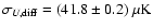 .
These results do not allow
one to extract the small sky signal (we expect
.
These results do not allow
one to extract the small sky signal (we expect

 for Q
and U in the concordance model with 3.5
pixelization), but are fully consistent with the
level of noise of our receivers (see Fig. 37).
for Q
and U in the concordance model with 3.5
pixelization), but are fully consistent with the
level of noise of our receivers (see Fig. 37).
![\begin{figure}
\par\includegraphics[width=7.5cm,clip]{3891f37a.eps}
\end{figure}](/articles/aa/full/2006/42/aa3891-05/Timg427.gif) |
Figure 37:
Histogram of the quantity
 from simulations of the B2K
observations of the Deep Region. The simulations used the
concordance model to generate CMB maps and realistic noise
simulations for all the 145 GHz detectors. The measured values of
from simulations of the B2K
observations of the Deep Region. The simulations used the
concordance model to generate CMB maps and realistic noise
simulations for all the 145 GHz detectors. The measured values of
 and
and
 are plotted as vertical
dashed lines.
are plotted as vertical
dashed lines. |
| Open with DEXTER |
In fact the uncertainty in
 and
and
 obtained from realistic simulations of the
instrumental noise and of the observations is 25
obtained from realistic simulations of the
instrumental noise and of the observations is 25
 (see
Fig. 37). So we have
(see
Fig. 37). So we have
 ,
and
,
and
 .
For the
polarization degree we have
.
For the
polarization degree we have
 .
This sets
an upper limit to the rms linear polarization of the sky of
.
This sets
an upper limit to the rms linear polarization of the sky of
 (95
confidence level). This limit is
close to the
(95
confidence level). This limit is
close to the
 expected for the CMB polarization
signal in the 3.5
pixelization.
expected for the CMB polarization
signal in the 3.5
pixelization.
Power spectrum methods provide much more powerful tools to extract
the sky polarization from noisy maps, since it is much easier to
separate different components according to their multipole
content. In particular the effect of low-frequency noise and drift
mostly affects the low multipoles
 .
While the
rms analysis above does not separate the different multipoles,
the spectral analysis does; artifacts at low multipoles can be
removed, allowing a much more sensitive probe for signal at higher
multipoles. The application of these methods to B03 is described
in detail in Piacentini et al. (2006) and Montroy et al. (2006), where it is shown that there is in fact a CMB
polarization signal hidden in the Q and U maps described here.
.
While the
rms analysis above does not separate the different multipoles,
the spectral analysis does; artifacts at low multipoles can be
removed, allowing a much more sensitive probe for signal at higher
multipoles. The application of these methods to B03 is described
in detail in Piacentini et al. (2006) and Montroy et al. (2006), where it is shown that there is in fact a CMB
polarization signal hidden in the Q and U maps described here.
The results of this flight of BOOMERanG demonstrate the
effectiveness of balloon-borne 145 GHz PSBs in the measurement of
CMB anisotropy and polarization, and in the survey of mm-wave
emission from the interstellar medium.
In our three frequency bands the long duration balloon platform
offers an excellent tradeoff between cost and performance. With
bolometers cooled to 0.3 K, observing through an uncooled
telescope, the stratosphere at altitudes 25 Km offers a
very stable environment, and optimal loading conditions for these
measurements.
During the entire flight, the B03 cryogenics and electronics
produced the correct environment (in terms of operating
temperature stability, radiative background level and stability,
and electromagnetic disturbances) to operate the PSBs. These
performed very closely to the theoretical limit, as described in
Sects. 6.4 and 6.5. The attitude
control system allowed us to reconstruct the pointing of the
telescope with an accuracy of a few arcmin, sufficient for the
main purpose of the experiment, i.e. the measurement of the power
spectra of CMB anisotropy and polarization.
B03 produced maps of the sky at 145, 245 and 345 GHz in two
high-latitude regions and one region at low Galactic latitudes, in
the Southern sky, producing a new survey of more than 1000 square
degrees with
resolution. At high latitudes degree
and sub-degree scale anisotropy of the CMB is evident in the 145, 245 and 345 GHz maps. The rms fluctuation of the sky temperature
measured from the 145 GHz map is perfectly consistent with the
current CDM model for the anisotropy of the CMB. The 145 GHz Stokes Q and U maps presented here allow a statistical (power
spectrum) detection of CMB polarization at 145 GHz, as discussed
in companion papers.
The approach discussed here also shows the effectiveness of
multi-band observations in monitoring the foreground signal. The
Galactic and extragalactic foreground is negligible (
compared to the cosmological signal both in anisotropy and in
polarization) at 145 GHz and at high Galactic latitudes. Based on
the SFD maps, about 40% of the sky has ISD contamination equal
or lower than in the deep survey region studied here. Future
B-modes searches, seeking a much smaller polarization signal, will
be heavily affected by the foregrounds measured here.
The results presented here are comparable in sensitivity to those
published using interferometric techniques at lower frequencies;
however, this measurement is the first using bolometric detectors,
which can be scaled to large numbers and high sensitivity for
future investigations of CMB polarization. In the nearer term,
the measurements presented here provide a glimpse at what the
Planck HFI instrument will achieve at 145 GHz; using the same
technology (PSB detectors), the HFI will reach over the whole sky
roughly the same sensitivity per pixel as was achieved by B03 in
the deep survey.
Acknowledgements
We gratefully acknowledge support from the CIAR, CSA, and NSERC in
Canada; Agenzia Spaziale Italiana, University La Sapienza and
Programma Nazionale Ricerche in Antartide in Italy; PPARC and the
Leverhulme Trust in the UK; and NASA (awards NAG5-9251 and
NAG5-12723) and NSF (awards OPP-9980654 and OPP-0407592) in the
USA. Additional support for detector development was provided by
CIT and JPL. C.B.N. acknowledges support from a Sloan Foundation
Fellowship, W.C.J. and T.E.M. were partially supported by NASA GSRP
Fellowships. Field, logistical, and flight support were supplied
by USAP and NSBF; data recovery was particularly appreciated. This
research used resources at NERSC, supported by the DOE under
Contract No. DE-AC03-76SF00098, and the MacKenzie cluster at CITA,
funded by the Canada Foundation for Innovation. We also thank the
CASPUR (Rome-ITALY) computational facilities and the Applied
Cluster Computing Technologies Group at the Jet Propulsion
Laboratory for computing time and technical support. Some of the
results in this paper have been derived using the HEALPix
package (Gorski et al. 1999).
- Abroe, M. E.,
Borrill, J., Ferreira, P. G., et al. 2004, ApJ, 605, 607 [NASA ADS] [CrossRef] (In the text)
- Aliaga, A. M.,
Martinez-Gonzalez, E., Cayon, L., et al. 2003, New Astron. Rev.,
47, 821 [NASA ADS] (In the text)
- Barkats, D.,
Bischoff, C., Farese, P., et al. 2005, ApJ, 619, L127 [NASA ADS] [CrossRef] (In the text)
-
Battistelli, E. S., De Petris, M., Lamagna, L., et al. SPIE
conference proceedings, Astronomical telescopes and instrumentation
[arXiv:astro-ph/0209180]
(In the text)
- Bennett, C.,
Halpern, M., Hinshaw, G., et al. 2003, ApJS, 148, 1 [NASA ADS] [CrossRef] (In the text)
- Benoit, A., Ade, P.
A. R., Amblard, A., et al. , 2003, A&A, 424, 571 [NASA ADS] [CrossRef] [EDP Sciences] (In the text)
- Bernardi, G.,
Carretti, E., Cortiglioni, S., et al. 2003, ApJL, 594, 5 [NASA ADS] [CrossRef] (In the text)
- Bond, J. R., Jaffe, A.
H., & Knox, L. 1998, Phys. Rev., D57, 2117 [NASA ADS] (In the text)
- Bond, J. R., Jaffe, A.
H., & Knox, L. 2000, AJ, 533, 19 [NASA ADS] [CrossRef] (In the text)
- Boyle, L. A.,
Steinhardt, P. J., & Turok, N. 2004, Phys. Rev., D70,
023504 [NASA ADS] (In the text)
- Bridle, S. L. ,
Zehavi, I., Dekel, A., et al. 2001, MNRAS, 321, 333 [NASA ADS] (In the text)
- Brouw, W. N., &
Spoelstra, T. A. T. 1976, A&AS, 26, 129 [NASA ADS] (In the text)
- Bucher, M.,
Moodley, K., & Turok, N. 2002, Phys. Rev., D66, 023528 [NASA ADS] (In the text)
- Caderni, N.,
Fabbri, R., Melchiorri B., Melchiorri, F., & Natale, V. 1978,
Phys. Rev. D., 17, 1901 [NASA ADS] [CrossRef]; 1908
(In the text)
- Carretti, E.,
Tascone, R., Cortiglioni, S., Monari, J., & Orsini, M. 2001,
New Astron., 6, 173 [NASA ADS] (In the text)
- Carretti, E.,
McConnell, D., McClure-Griffiths, N. M., et al. 2005, MNRAS, 360,
L10 [NASA ADS] (In the text)
- Cartwright,
J. K., Pearson, T. J., Readhead, A. C. S. , Shepherd, M. C., &
Sievers, J. L. 2005, ApJ, 623, 11 [NASA ADS] [CrossRef] (In the text)
- Catalano, A.,
Conversi, L., De Gregori, S., et al. 2004, New Astron., 10, 79 [NASA ADS] (In the text)
- Copeland, E.
J., Kolb, E. W., Liddle, A. R., & Lidsey, J. E. 1993a, Phys.
Rev. Lett., 71, 219 [NASA ADS] [CrossRef] (In the text)
- Copeland, E.
J., Kolb, E. W., Liddle, A. R., & Lidsey, J. E. 1993b, Phys.
Rev. D, 48, 2529 [NASA ADS] [CrossRef]
-
Cortiglioni, S., Bernardi, G., Carretti, E., et al. 2004, New
Astron., 9, 297 [NASA ADS] (In the text)
- Crill, B. P., Ade, P.
A. R., Artusa, D. R., et al. 2003, ApJS, 148, 527 [NASA ADS] [CrossRef] (In the text)
- T. M., Dame, D.,
Hartmann, & Thaddeus, P. 2001, ApJ, 547, 792 [NASA ADS] [CrossRef] (In the text)
- de
Bernardis, P., De Gasperis, G., Masi, S., & Vittorio, N. 1994,
ApJ, 433, L1 [NASA ADS] [CrossRef] (In the text)
- de
Bernardis, P., Ade, P. A. R., Bock, J. J., et al. 2000, Nature,
404, 955 [NASA ADS] [CrossRef] (In the text)
- de
Bernardis, P., Ade, P., Bock, J., et al. 2002, ApJ, 564, 559 [NASA ADS] [CrossRef] (In the text)
- de
Bernardis, P., Ade, P. A. R., Balbi, A., et al. 2003, in
[arXiv:astro-ph/0311396], IAU Symp., 216, Maps of the
Cosmos. Sydney 14-17 July 2003, ASP Conf. Ser.
(In the text)
- de
Gasperis, G., Balbi, A., Cabella, P., Natoli, P., & Vittorio,
N. 2005, A&A, 436, 1159 [NASA ADS] [CrossRef] [EDP Sciences] (In the text)
- De Troia, G.,
Ade, P. A. R., Bock, J. J., et al. 2003, MNRAS, 343, 284 [NASA ADS] (In the text)
-
Delabrouille, J., Kaplan, J., & The Planck HFI Consortium.
2002, in Astrophysical Polarized Backgrounds, ed. S. Cecchini, S.
Cortiglioni, R. Sault, & C. Sbarra (New York: AIP), AIP Conf.
Proc., 609, 135
(In the text)
- Djik, J., Van
Diepenbeek, C. T. W., Maanders, E. J., & Thurlings, L. F. G.
1974, I.E.E.E. Trans. on Antennas and Propagation, AP22, 513 [CrossRef] (In the text)
- Dodelson, S.,
& Knox, L. 2000, Phys. Rev. Lett., 84, 3523 [NASA ADS] [CrossRef] (In the text)
- Doré, O.,
Teyssier, R., Bouchet, F. R., Vibert, D., et al. 2001, A&A,
374, 358 [NASA ADS] [CrossRef] [EDP Sciences]; see also http://ulysse.iap.fr/cmbsoft/mapcumba/
(In the text)
- Douspis, M.,
Bartlett, J. G., Blanchard, A., & Le Dour, M. 2001, A&A,
368, 1 [NASA ADS] [CrossRef] [EDP Sciences] (In the text)
- Dragone, M. 1974,
IEEE Trans. AP, 22, 472; 1982, IEEE Trans. AP, 30, 331
(In the text)
- Efstathiou,
G., & Bond, J. R. 1999, MNRAS, 304, 75 [NASA ADS] (In the text)
- Farese, P.,
Dall'Oglio, G., Gundersen, J., et al. 2004, ApJ, 610, 625 [NASA ADS] [CrossRef] (In the text)
- Ferreira, P.
G., & Jaffe, A. H. 2000, MNRAS, 312, 89 [NASA ADS] (In the text)
- Finkbeiner,
D., Davis, M., & Schlegel, D. 1999, ApJ, 524, 867 [NASA ADS] [CrossRef] (In the text)
- Fischer, M. L.,
Alsop, D. C., Cheng, E. S., et al. 1992, ApJ, 388, 242 [NASA ADS] [CrossRef] (In the text)
- Gordon, C., &
Lewis, A. 2003, Phys. Rev., D67, 123513 [NASA ADS] (In the text)
- Gervasi, M.,
Boella, G., Cavaliere, F., et al. 2003, Proc. SPIE
[arXiv:astro-ph/0301350]
(In the text)
- Giommi, P., &
Colafrancesco, S. 2004, A&A, 414, 7 [NASA ADS] [CrossRef] [EDP Sciences] (In the text)
- Gorski, K. M.,
Hivon, E., & Wandelt, B. D. 1999, in Proceedings of the MPA/ESO
Cosmology Conference, Evolution of Large-Scale Structure, ed. A. J.
Banday, R. S. Sheth, & L. Da Costa, PrintPartners Ipskamp, NL,
37 (also [arXiv:astro-ph/9812350])
(In the text)
- Gundersen, J.
O., and the KUPID collaboration 2003, New Astron. Rev., 47,
1097 [NASA ADS] (In the text)
- Guth, A., & Pi, S.
Y. 1982, Phys. Rev. Lett., 49, 1110 [NASA ADS] [CrossRef] (In the text)
- Hamilton, J.
Ch, Benoit, A., the Archeops Collaboration 2003, Comptes Rendus
Physique Académie des Sciences, 4, 853
[arXiv:astro-ph/0310788]
(In the text)
- Hanany, S.,
Matsumura, T., Johnson, B., et al. 2003, IEEE Trans. Appl.
Supercond., 13, 2128 [CrossRef] (In the text)
- Hedman, M. N.,
Barkats, D., Gundersen, J. O., McMahon, J. J., Staggs, S. T., et
al. 2002, ApJ, 573, L73 [NASA ADS] [CrossRef] (In the text)
- Hoffman, Y.,
& Ribak, E. 1991, ApJ, 380, L5 [NASA ADS] [CrossRef] (In the text)
- Holmes, W.,
Gildemeister, J. M., & Richards, P. L. 1998, Appl. Phys. Lett.,
72, 2250 [NASA ADS] [CrossRef] (In the text)
- Holzapfel, W.
L., Wilbanks, T. M., Ade, P. A. R., et al. 1997, ApJ, 479, 17 [NASA ADS] [CrossRef] (In the text)
- Hu, W., & White, M.
1997, New Astron., 2, 323 [NASA ADS] (In the text)
- Jaffe, A. H., Ade, P.
A. , Balbi, A., et al. 2001, Phys. Rev. Lett., 86, 3475 [NASA ADS] [CrossRef] (In the text)
- Johnson, B. R.,
Abroe, M. E., Ade, P., et al. 2003, New Astron. Rev., 47, 1067 [NASA ADS] (In the text)
- Jones, R. J. 1953, J.
Opt. Soc. Am, 43, 1 (In the text)
- Jones, B. 2005,
Ph.D. Thesis, California Institute of Technology
(In the text)
- Jones, B., Bhatia, R.
S., Bock, J. J., Lange, A. E. 2003, A Polarization Sensitive
Bolometric Detector for Observations of the Cosmic Microwave
Background 2003, SPIE, 4855, 227 [NASA ADS]
[arXiv:astro-ph/0209132]
(In the text)
- Jones, B., Ade, P. A.
R., Bock, J. J., Bond, J. R., Borrill, J., et al. 2006a, ApJ, 647,
823 [NASA ADS] [CrossRef] (In the text)
- Jones, B., Montroy,
T., Crill, B., Contaldi, C., Kisner, et al. 2006b, A&A,
submitted [arXiv:astro-ph/0606606]
(In the text)
- Kaiser, N. 1983,
MNRAS, 202, 1169 [NASA ADS] (In the text)
- Kalman, R. E. 1960,
J. Basic Engineering, 82D, 35 (In the text)
-
Kamionkowski, M., Kosowsky, A., & Stebbins, A. 1997, Phys. Rev.
D, 55, 7368 [NASA ADS] [CrossRef] (In the text)
- Kaplinghat,
M., Chu, M., Hainam, Z., Holder, G. P. L. Knox, et al. 2003, ApJ,
583, 24 [NASA ADS] [CrossRef] (In the text)
- Keating, B. G.,
O'Dell, C. W., de Oliveira-Costa, A., Klawikowski, S., &
Stebor, N. 2001, ApJ, 560, L1 [NASA ADS] [CrossRef] (In the text)
- Keating, B. G.,
O'Dell, C. W., Gundersen, J. O., Piccirillo, L., Stebor, N., et al.
2003, ApJS, 144, 1 [NASA ADS] [CrossRef] (In the text)
- Keating, B. G.,
et al.,
http://www.astro.caltech.edu/~lgg/bicep/BICEP_color.pdf
(In the text)
- Kogut, A., Spergel,
D. N., Barnes, C., et al. 2003, ApJS, 148, 161 [NASA ADS] [CrossRef] (In the text)
- Kolb, E. W., &
Turner, M. S. 1990, The Early Universe (Addison-Welsey)
(In the text)
- Komatsu, E.,
Kogut, A., Nolta, M., et al. 2003, ApJS, 148, 119 [NASA ADS] [CrossRef] (In the text)
- Kovac, J., Leitch,
E., Pryke, C., et al. 2002, Nature, 420, 772 [NASA ADS] [CrossRef] (In the text)
- Kuo, C. L., Ade, P. A.
R., Bock, J. J., et al. 2004, ApJ, 600, 32 [NASA ADS] [CrossRef] (In the text)
- Lange, A. E., Freund,
M. M., Sato, S., et al. 1994, ApJ, 428, 384 [NASA ADS] [CrossRef] (In the text)
- Lange, A., Ade, P. A.
R., Bock, J., et al. 2001, Phys. Rev. D, 63, 042001 [NASA ADS] [CrossRef] (In the text)
- Leach, S. M., &
Liddle, A. R. 2003, Phys. Rev. D, 68, 123508 [NASA ADS] [CrossRef] (In the text)
- Lee, C., Ade, P. A. R.,
& Haynes, C. V. 1996, ESA SP-388, 81
(In the text)
- Leitch, E., Kovac,
J. M., Pryke, C., et al. 2002, Nature, 420, 763 [NASA ADS] [CrossRef]
- Leitch, E., Kovac,
J., Halverson, N., et al. 2005, ApJ, 624, 10 [NASA ADS] [CrossRef] (In the text)
- Lewis, A., &
Bridle, S. 2002, Phys. Rev. D, 66, 103511 [NASA ADS] [CrossRef] (In the text)
- Linde, A. 1983, Phys.
Lett., B129, 177 [NASA ADS] (In the text)
- Lubin, P., &
Smoot, G. 1981, ApJ, 245, 1 [NASA ADS] [CrossRef] (In the text)
- Mac Tavish
C., Ade, P. A. R., Bock, J. J., et al. 2006, ApJ, 647, 799 [NASA ADS] [CrossRef] (In the text)
- Masi, S. 1984, Search
for the Cosmic Background Polarization, in Gamow Cosmology, ed. R.
Ruffini, & F. Melchiorri, LXXXVI Course of the International
School of Physics E. Fermi, Varenna, 1984, 310, Soc. It. Fisica,
Bologna
(In the text)
- Masi, S., Aquilini, E.,
Cardoni, P., et al. 1998, Cryogenics, 38, 319 [CrossRef] (In the text)
- Masi, S., Cardoni, P.,
de Bernardis, P., et al. 1999, Cryogenics, 39, 217 [NASA ADS] [CrossRef] (In the text)
- Masi, S., Ade, P. A.
R., Bock, J. J., et al. 2001, ApJ, 553, L93 [NASA ADS] [CrossRef] (In the text)
- Masi, S., Ade, P. A.
R., Bock, J. J., et al. 2002, in AIP Conf. Proc. 609, Astrophysical
Polarized Backgrounds, ed. S. Cecchini, S. Cortiglioni, R. Sault,
& C. Sbarra (New York: AIP), 122
(In the text)
- Mather, J. C. 1982,
Appl. Opt., 21, 1125 [NASA ADS] (In the text)
- Mauskopf, P.
D., Bock, J. J., Del Castillo, H., Holzapfel, W. L., & Lange,
A. E. 1997, Appl. Opt., 36, 4
- Montroy T. 2003,
Ph.D. Thesis, University of California at Santa Barbara
(http://cmb.phys.cwru.edu/tom/thesis.ps)
(In the text)
- Montroy, T., Ade,
P. A. R., Bock, J. J., et al. 2006, ApJ, 647, 813 [NASA ADS] [CrossRef] (In the text)
- Mukhanov, V.
F., & Chibisov, G. V. 1981, JETP Lett., 33, 532 [NASA ADS] (1981, Zh.
Eksp. Teor. Fiz., 33, 549) see also
[arXiv:astro-ph/0303077]
(In the text)
- Nanos, G. P. 1979,
ApJ, 232, 241 [NASA ADS] [CrossRef] (In the text)
- Natoli, P., de
Gasperis, G., Gheller, C., & Vittorio, N. 2001, A&A, 372,
346 [NASA ADS] [CrossRef] [EDP Sciences] (In the text)
- Natoli, P.,
Marinucci, D., Cabella, P., de Gasperis, G., & Vittorio, N.
2002, A&A, 383, 110 [CrossRef] (In the text)
-
Netterfield, C. B., Devlim, M. J., Jarosik, N., Page, L., &
Wollack, E. J. 1997, ApJ, 474, 47 [NASA ADS] [CrossRef] (In the text)
-
Netterfield, C., Ade, P., Bock, J., et al. 2002, ApJ, 571, 604 [NASA ADS] [CrossRef] (In the text)
- Padin, S., Shepherd,
M. C., Cartwright, J. K., et al. 2002, PASP, 114, 83 [NASA ADS] [CrossRef] (In the text)
- Page, L., Hinshaw, G.,
Komatsu, E., et al. 2006, ApJ, submitted
[arXiv:astro-ph/0603450]
(In the text)
- Partridge,
B., Nowakowski, J., & Martin, H. M. 1988, Nature, 331, 146 [NASA ADS] [CrossRef] (In the text)
- Peiris, H. V.,
Komatsu, E., Verde, L., et al. 2003, ApJS, 148, 213 [NASA ADS] [CrossRef] (In the text)
- Piacentini,
F., Ade, P. A. R., Bhatia, R. S., et al. 2002, ApJS, 138, 315 [NASA ADS] [CrossRef] (In the text)
- Piacentini
F., Ade, P. A. R., Bock, J. J., et al. 2006, ApJ, 647, 833 [NASA ADS] [CrossRef] (In the text)
- Piccirillo,
L., Ade, P. A. R., Bock, J. J., Bowden, M., Church, et al. 2002, in
Astrophysical Polarized Backgrounds, ed. S. Cecchini, S.
Cortiglioni, R. Sault, & C. Sbarra (New York: AIP), AIP Conf.
Proc., 609, 159
(In the text)
- Ponthieu, N.,
Macías-Pérez, J. F., Tristram, M., Ade, P. A. R.,
Amblard, A., et al. 2005, A&A, 444, 327 [NASA ADS] [CrossRef] [EDP Sciences] (In the text)
- Polenta, G., Ade,
P. A. R., Bock, J., Bond, J., Borrill, J., et al. 2002, ApJ, 572,
L27 [NASA ADS] [CrossRef] (In the text)
- Polenta, G. 2004,
Ph.D. Thesis, University of Rome La Sapienza
(In the text)
- Prunet, S., Ade, P.
A. R., Bock, J. J., Bond, J. R., Borrill, J., et al. 2001, proc. of
the MPA/ESO/MPA conference, Mining the Sky
[arXiv:astro-ph/0101073]
(In the text)
- Richards, P. L.
1994, J. Appl. Phys., 76, 1 [NASA ADS] [CrossRef] (In the text)
- Readhead, A. C.
S., Myers, S. T., Pearson, T. J., Sievers, J. L., Mason, B. S., et
al. 2004, Science, 306, 836 [NASA ADS] [CrossRef] (In the text)
- Rees, M. 1968, ApJ, 53,
L1 [NASA ADS] [CrossRef] (In the text)
- Romeo, G., de
Bernardis, P., di Stefano, G., Masi, S., Piacentini, F., et al.
2002, in Experimental Cosmology at Millimetre Wavelengths, AIP
Conf. Proc., 616, 59
(In the text)
- Ruhl, J. E., Ade, P.,
Bock, J., et al. , 2003, ApJ, 599, 786 [NASA ADS] [CrossRef] (In the text)
- Savage, R., Battye,
R. A., Carreira, P., et al. 2004, MNRAS, 349, 973 [NASA ADS] (In the text)
- Schlegel, D.
J., Finkbeiner, D. P., & Davis, M. 1999, ApJ, 500, 525 [NASA ADS] [CrossRef] (In the text)
- Seljak, U., Pen,
U., & Turok, N. 1997, Phys. Rev. Lett., 79, 1615 [NASA ADS] [CrossRef] (In the text)
- Song, Y. S., &
Knox, L. 2003, Phys. Rev., D68, 043518 [NASA ADS] (In the text)
- Spergel, D. N.,
Verde, L., Peiris, H. V., et al. 2003, ApJS, 148, 175 [CrossRef] (In the text)
- Spergel, D. N.,
Bean, R., Dore', O., et al. 2006, ApJ, in press
[arXiv:astro-ph/0603449]
(In the text)
- Steinhardt,
P. J., & Turok, N. 2002, Science, 296, 1436 [NASA ADS] [CrossRef] (In the text)
-
Subrahmanyan, R., Kesteven, M. J., Ekers, R. D., Sinclair, M.,
& Silk, J. 2000, MNRAS, 315, 808 [NASA ADS] (In the text)
- Tegmark, M.,
& Zaldarriaga, M. 2000a, ApJ, 544, 30 [NASA ADS] [CrossRef] (In the text)
- Tegmark, M.,
& Zaldarriaga, M. 2000b, Phys. Rev. Lett., 85, 2240 [NASA ADS] [CrossRef]
- Tegmark, M.,
Strauss, M., Blanton, M., et al. 2004, Phys. Rev. D, 69,
103501 [NASA ADS] [CrossRef] (In the text)
- Tristram, M.,
Hamilton, J.-C., Macias-Perez, J. F., & Renault, C. 2004, Phys.
Rev. D, 69, 123008 [NASA ADS] [CrossRef] (In the text)
- Turner, M. S. 1993,
Phys. Rev. D., 48, 5539 [NASA ADS] [CrossRef] (In the text)
- Villa, F., Mandolesi,
N., Bersanelli, M., Butler, R. C., Burigana, C., et al. 2002, in
Astrophysical Polarized Backgrounds, ed. S. Cecchini, S.
Cortiglioni, R. Sault, & C. Sbarra (New York: AIP), AIP Conf.
Proc., 609, 144
(In the text)
- Wollack, E. J.,
Devlin M. J., Jarosik, N., Netterfield, C. B., Page, L., et al.
1997, ApJ, 476, 440 [NASA ADS] [CrossRef] (In the text)
- Yamada, Y.,
Mitsuishi, A., & Yoshinaga, H. 1962, J. Opt. Soc. Am., 52,
17
- Yun, M., Beeman, J.,
Bhatia, R., Bock, J., Holmes, W., et al. 2003, Proc. SPIE, 4855,
136 [NASA ADS] (In the text)
-
Zaldarriaga, M. 2003 [arXiv:astro-ph/0305272]
(In the text)
-
Zaldarriaga, M., & Seljak, U. 1997, Phys. Rev. D, 55, 1830 [NASA ADS] [CrossRef] (In the text)
-
Zaldarriaga, M., & Seljak, U. 1998, Phys. Rev. D, 58,
023003 [NASA ADS] [CrossRef] (In the text)
Copyright ESO 2006
![\begin{figure}
\par\includegraphics[width=7.2cm,clip]{3891f01a.eps}
\end{figure}](/articles/aa/full/2006/42/aa3891-05/img139.gif)
![\begin{figure}
\par\includegraphics[width=7.2cm,clip]{3891f02a.eps}
\end{figure}](/articles/aa/full/2006/42/aa3891-05/img144.gif)
![\begin{figure}
\par\includegraphics[width=8.2cm,clip]{3891f04a.eps}
\end{figure}](/articles/aa/full/2006/42/aa3891-05/img150.gif)
![\begin{figure}
\par\includegraphics[width=7.2cm,clip]{3891f05a.eps}
\end{figure}](/articles/aa/full/2006/42/aa3891-05/img160.gif)
![\begin{figure}
\par\includegraphics[width=7.6cm,clip]{3891f06a.eps}
\end{figure}](/articles/aa/full/2006/42/aa3891-05/img168.gif)
![\begin{figure}
\par\includegraphics[width=7cm,clip]{3891f07a.eps}
\end{figure}](/articles/aa/full/2006/42/aa3891-05/img171.gif)
![\begin{figure}
\par\includegraphics[width=7.7cm,clip]{3891f08a.eps}
\end{figure}](/articles/aa/full/2006/42/aa3891-05/img175.gif)
![\begin{figure}
\par\includegraphics[angle=90,width=7.6cm,clip]{3891f09a.eps}
\end{figure}](/articles/aa/full/2006/42/aa3891-05/img188.gif)
![\begin{figure}
\par\includegraphics[angle=90,width=6.2cm,clip]{3891f10a.eps} %
\end{figure}](/articles/aa/full/2006/42/aa3891-05/img198.gif)
![\begin{figure}
\par\includegraphics[width=7.6cm,clip]{3891f12a.eps}
\end{figure}](/articles/aa/full/2006/42/aa3891-05/img245.gif)
![\begin{figure}
\par\includegraphics[angle=0,width=4cm]{3891f13a.eps}\includegrap...
...4cm]{3891f13g.eps}\includegraphics[angle=0,width=4cm]{3891f13h.eps}
\end{figure}](/articles/aa/full/2006/42/aa3891-05/img247.gif)
![\begin{figure}
\par\includegraphics[angle=0,width=4cm]{3891f14a.eps}\includegrap...
...=4cm]{3891f14g.eps}\includegraphics[angle=0,width=4cm]{3891f14h.eps}\end{figure}](/articles/aa/full/2006/42/aa3891-05/img251.gif)
![\begin{figure}
\par\includegraphics[angle=90,width=7.2cm,clip]{3891f15a.eps}
\end{figure}](/articles/aa/full/2006/42/aa3891-05/img254.gif)
![\begin{figure}
\par\includegraphics[angle=90,width=7.5cm,clip]{3891f16a.eps}
\end{figure}](/articles/aa/full/2006/42/aa3891-05/img255.gif)
![\begin{figure}
\par\includegraphics[angle=90,width=8.5cm,clip]{3891f17a.eps}
\end{figure}](/articles/aa/full/2006/42/aa3891-05/img256.gif)
![\begin{figure}
\par\includegraphics[angle=90,width=7.8cm,clip]{3891f19a.eps}
\end{figure}](/articles/aa/full/2006/42/aa3891-05/img258.gif)
![\begin{figure}
\par\includegraphics[angle=0,width=7cm,clip]{3891f20a.eps}
\end{figure}](/articles/aa/full/2006/42/aa3891-05/img259.gif)
![\begin{figure}
\par\includegraphics[width=7.1cm,clip]{3891f21a.eps}
\end{figure}](/articles/aa/full/2006/42/aa3891-05/img266.gif)
![\begin{figure}
\par\includegraphics[width=7.7cm,clip]{3891f22a.eps}
\end{figure}](/articles/aa/full/2006/42/aa3891-05/img288.gif)
![\begin{figure}
\par\includegraphics[angle=90,width=7.6cm,clip]{3891f23a.eps}
\end{figure}](/articles/aa/full/2006/42/aa3891-05/img291.gif)
![\begin{figure}
\par\includegraphics[width=7.6cm,clip]{3891f24a.eps}
\end{figure}](/articles/aa/full/2006/42/aa3891-05/img331.gif)
![\begin{figure}
\par\includegraphics[angle=0,width=5cm]{3891f25aCMJN.eps}\include...
...1f25eCMJN.eps}\includegraphics[angle=0,width=5cm]{3891f25fCMJN.eps}
\end{figure}](/articles/aa/full/2006/42/aa3891-05/img336.gif)
![\begin{figure}
\par\includegraphics[width=7.3cm,clip]{3891f26a.eps}\par\vspace*{...
...}\par\vspace*{3mm}
\includegraphics[width=7.3cm,clip]{3891f26c.eps}
\end{figure}](/articles/aa/full/2006/42/aa3891-05/img337.gif)
![\begin{figure}
\par\includegraphics[width=8.5cm,clip]{3891f27aCMJN.eps}
\end{figure}](/articles/aa/full/2006/42/aa3891-05/img348.gif)
![\begin{figure}
\par\includegraphics[angle=0,width=5.3cm,clip]{3891f28aCMJN.eps}\...
...N.eps}\includegraphics[angle=0,width=5.3cm,clip]{3891f28fCMJN.eps}
\end{figure}](/articles/aa/full/2006/42/aa3891-05/img349.gif)
![\begin{figure}
\par\includegraphics[height=4.7cm,width=5.2cm,clip]{3891f29aCMJN....
...eps}\includegraphics[height=4.7cm,width=5cm,clip]{3891f29fCMJN.eps}
\end{figure}](/articles/aa/full/2006/42/aa3891-05/img350.gif)
![\begin{figure}
\par\includegraphics[angle=0,width=5.2cm,clip]{3891f30aCMJN.eps}\...
...*{2mm}
\includegraphics[angle=0,width=5.2cm,clip]{3891f30cCMJN.eps}
\end{figure}](/articles/aa/full/2006/42/aa3891-05/img356.gif)
![\begin{figure}
\par\includegraphics[width=7.3cm,clip]{3891f31a.eps}
\end{figure}](/articles/aa/full/2006/42/aa3891-05/img376.gif)
![\begin{figure}
\par\includegraphics[width=7.5cm,clip]{3891f32a.eps}
\end{figure}](/articles/aa/full/2006/42/aa3891-05/img394.gif)
![\begin{figure}
\par\includegraphics[width=7.5cm,clip]{3891f33a.eps}
\end{figure}](/articles/aa/full/2006/42/aa3891-05/img395.gif)
![\begin{figure}
\par\includegraphics[width=6cm,clip]{3891f34a.eps}\par\vspace*{3mm}
\includegraphics[width=6cm,clip]{3891f34b.eps}
\end{figure}](/articles/aa/full/2006/42/aa3891-05/img412.gif)
![\begin{figure}
\par\includegraphics[width=7cm,clip]{3891f35a.eps}\par\vspace*{2mm}
\includegraphics[width=7cm,clip]{3891f35b.eps}
\end{figure}](/articles/aa/full/2006/42/aa3891-05/img413.gif)
![\begin{figure}
\par\includegraphics[width=7cm,clip]{3891f36a.eps}
\end{figure}](/articles/aa/full/2006/42/aa3891-05/img417.gif)
![\begin{figure}
\par\includegraphics[width=7.5cm,clip]{3891f37a.eps}
\end{figure}](/articles/aa/full/2006/42/aa3891-05/img427.gif)