A&A 452, 897-906 (2006)
DOI: 10.1051/0004-6361:20054047
S. Cabrit 1 - J. Pety 1,2 - N. Pesenti 3 - C. Dougados 3
1 - LERMA, UMR 8112 du CNRS, Observatoire de Paris, 61 Av.
de l'Observatoire, 75014 Paris, France
2 - IRAM, 300 rue de la Piscine, 38406 Grenoble Cedex, France
3 - Laboratoire d'Astrophysique, UMR 5571 du CNRS,
Observatoire de Grenoble, France
Received 14 August 2005 / Accepted 6 March 2006
Abstract
We present interferometric maps of the RW Aur system
obtained with the IRAM Plateau de Bure Interferometer in CO(J=2-1),
CO(J=1-0), and nearby continuum. The sub-arcsecond angular resolution
(
![]() )
and high-sensitivity reached at 1.3 mm enable us
to resolve three molecular structures: (1) an optically thick
disk around RW Aur A in rotation about the optical jet axis, (2) a
disturbed asymmetric peak around RW Aur B, (3) a
600 AU-long "arm'' of material trailing from the RW Aur A
disk. Comparison with Keplerian models indicates that the RW Aur A
disk is the smallest detected so far around a T Tauri star (radius
40-57
)
and high-sensitivity reached at 1.3 mm enable us
to resolve three molecular structures: (1) an optically thick
disk around RW Aur A in rotation about the optical jet axis, (2) a
disturbed asymmetric peak around RW Aur B, (3) a
600 AU-long "arm'' of material trailing from the RW Aur A
disk. Comparison with Keplerian models indicates that the RW Aur A
disk is the smallest detected so far around a T Tauri star (radius
40-57
![]() )
and that the CO emitting layer at the outer edge is
warmer than the dust (
)
and that the CO emitting layer at the outer edge is
warmer than the dust (
![]() K) and relatively thick
(
K) and relatively thick
(
![]()
![]() ).
).
The morphology and kinematics of the detected features strongly suggest that we are witnessing tidal stripping of the primary disk by the recent fly-by of RW Aur B. We speculate that tidal dissipation might explain the warmer gas temperatures in the RW Aur A disk compared with typical T Tauri stars, and perhaps play a role in its elevated accretion rate. We also find that the rotation sense of the RW Aur A disk is opposite to transverse velocity shifts in the optical jet reported by Woitas et al. (2005, A&A, 432, 149). We argue that these transverse shifts are likely to represent only upper limits to the true jet rotation speed. The limits remain consistent with current models of MHD launching from the disk.
Key words: stars: individual: RW Aur - stars: formation - stars: circumstellar matter - ISM: molecules - radio lines: ISM
The young RW Aur system in Taurus-Auriga is composed of two actively
accreting "Classical'' T Tauri stars (hereafter denoted CTTS): an
early-K star, RW Aur A, and a 2-3 mag fainter secondary located
1.5'' away, RW Aur B (Stout-Batalha et al. 2000; Herbig & Bell 1988; Duchêne et al. 1999). A third, faint
K-band source denoted RW Aur C was reported 0.12'' from B
(Ghez et al. 1993), but was not confirmed by subsequent HST optical
imaging (White & Ghez 2001; Ghez et al. 1997). Resolved photometry and recent
evolutionary tracks indicate masses of 1.3-1.4 ![]() for RW Aur A
and 0.7-0.9
for RW Aur A
and 0.7-0.9 ![]() for RW Aur B (Ghez et al. 1997; Woitas et al. 2001) at a
distance d = 140 pc (Bertout et al. 1999).
for RW Aur B (Ghez et al. 1997; Woitas et al. 2001) at a
distance d = 140 pc (Bertout et al. 1999).
Table 1: Observation parameters.
RW Aur A has attracted particular attention as it exhibits one of the
highest accretion rates among CTTS (
![]()
![]() ,
Hartigan et al. 1995; Basri & Bertout 1989), i.e. 10-100 times
higher than typical. It also drives one of the brightest atomic jets
in Taurus-Auriga, topped only by DG Tau and HL Tau
(Hirth et al. 1994; Woitas et al. 2002; Mundt & Eislöffel 1998; Dougados et al. 2000). RW Aur A is further
peculiar for showing large variations in radial velocity and emission
line properties over a 2.77 day period, attributed to a close low-mass
companion or to a rotationally modulated accretion "hot spot''
(Gahm et al. 1999; Petrov et al. 2001).
,
Hartigan et al. 1995; Basri & Bertout 1989), i.e. 10-100 times
higher than typical. It also drives one of the brightest atomic jets
in Taurus-Auriga, topped only by DG Tau and HL Tau
(Hirth et al. 1994; Woitas et al. 2002; Mundt & Eislöffel 1998; Dougados et al. 2000). RW Aur A is further
peculiar for showing large variations in radial velocity and emission
line properties over a 2.77 day period, attributed to a close low-mass
companion or to a rotationally modulated accretion "hot spot''
(Gahm et al. 1999; Petrov et al. 2001).
There are several important motivations to study the circumstellar environment of the RW Aur system at high angular resolution:
First, unlike other CTTS of comparable high accretion rates, RW Aur A
appears to have a particularly low disk mass
![]()
![]() from single-dish sub/mm continuum measurements
(Andrews & Williams 2005; Osterloh & Beckwith 1995), and lies in a region devoid of large-scale CO
emission (Ungerechts & Thaddeus 1987). Hence, one faces an acute problem to
replenish the disk and to sustain steady accretion at the
current rate beyond a thousand years, unless a hidden mass
reservoir is present on circumstellar scales.
from single-dish sub/mm continuum measurements
(Andrews & Williams 2005; Osterloh & Beckwith 1995), and lies in a region devoid of large-scale CO
emission (Ungerechts & Thaddeus 1987). Hence, one faces an acute problem to
replenish the disk and to sustain steady accretion at the
current rate beyond a thousand years, unless a hidden mass
reservoir is present on circumstellar scales.
Second, the RW Aur A jet is one of the four CTTS jets where
transverse velocity shifts have been recently detected with STIS/HST.
If these shifts are due to jet rotation, they would imply that the
optical jets are magnetically launched from the disk surface at
relatively large radii of 0.2-3
![]() ,
thus solving the long-lasting
question of the jet origin in CTTS (Woitas et al. 2005; Bacciotti et al. 2002; Coffey et al. 2004; Anderson et al. 2003). To support this interpretation, however, it is
crucial to check that the underlying disk rotates in the same sense as
the jet, as verified so far only in the DG Tau case (Testi et al. 2002).
,
thus solving the long-lasting
question of the jet origin in CTTS (Woitas et al. 2005; Bacciotti et al. 2002; Coffey et al. 2004; Anderson et al. 2003). To support this interpretation, however, it is
crucial to check that the underlying disk rotates in the same sense as
the jet, as verified so far only in the DG Tau case (Testi et al. 2002).
Finally, if CTTS jets do trace magnetized disk winds, a molecular
counterpart to the atomic optical jet will be present if MHD ejection
operates beyond a few
![]() (Safier 1993). The lack of ambient
molecular cloud toward RW Aur A means that any detected molecular
flow in this system would necessarily be ejected and not entrained
material: hence, such an observation would provide independent, direct
evidence for extended disk winds in CTTS.
(Safier 1993). The lack of ambient
molecular cloud toward RW Aur A means that any detected molecular
flow in this system would necessarily be ejected and not entrained
material: hence, such an observation would provide independent, direct
evidence for extended disk winds in CTTS.
To address these issues, we have undertaken an interferometric
mapping program of the RW Aur system at the Plateau de Bure IRAM
Interferometer in CO isotopologues at 1.3
![]() and 2.6
and 2.6
![]() ,
and in the nearby continuum. We detail our observations and data
reduction in Sect. 2, and describe the new features detected in our
maps and their kinematics in Sect. 3. In Sect. 4, we discuss
their physical properties and the resulting implications. We
summarize our conclusions in Sect. 5.
,
and in the nearby continuum. We detail our observations and data
reduction in Sect. 2, and describe the new features detected in our
maps and their kinematics in Sect. 3. In Sect. 4, we discuss
their physical properties and the resulting implications. We
summarize our conclusions in Sect. 5.
The characteristics of our line and continuum observations are detailed below. The resulting beam sizes and sensitivities are summarized in Table 1.
The first PdBI observations dedicated to this project were carried out with
6 antennas in the B and C configurations (baseline lengths from 48 to
331 m) during the winter 2002/2003. The
![]() J=1-0 and
J=1-0 and
![]() J=1-0
lines were observed simultaneously using the 3
J=1-0
lines were observed simultaneously using the 3
![]() receivers (tuned single
sideband at 110.1 GHz). Two correlator bands of 20 MHz were respectively
centered on the
receivers (tuned single
sideband at 110.1 GHz). Two correlator bands of 20 MHz were respectively
centered on the
![]() J=1-0 and
J=1-0 and
![]() J=1-0. The total
telescope time, including phase and amplitude calibrators and
tuning, amounts to 18 h. In practice, only data with phase noise better
than
J=1-0. The total
telescope time, including phase and amplitude calibrators and
tuning, amounts to 18 h. In practice, only data with phase noise better
than
![]() were used. The on-source integration time of useful
data is then 7.2 h.
were used. The on-source integration time of useful
data is then 7.2 h.
As a follow-up, we carried out observations of
![]() (J=1-0) at PdBI with 6
antennas in the A, C and D configurations (baseline lengths from 24 to
400 m) during the winter 2003/2004. The 3
(J=1-0) at PdBI with 6
antennas in the A, C and D configurations (baseline lengths from 24 to
400 m) during the winter 2003/2004. The 3
![]() receivers were tuned single
sideband at 115.271 GHz. One correlator band of 20 MHz was centered on the
receivers were tuned single
sideband at 115.271 GHz. One correlator band of 20 MHz was centered on the
![]() J=1-0. The total telescope time amounts to 32 h with 6
antennas. This leads to on-source integration time of useful data of
9.7 h after filtering out data with phase noise worse than
J=1-0. The total telescope time amounts to 32 h with 6
antennas. This leads to on-source integration time of useful data of
9.7 h after filtering out data with phase noise worse than
![]() .
.
Two bands of 320 MHz were used to measure the 2.7
![]() continuum during the
winter 2002/2003 and the 2.6
continuum during the
winter 2002/2003 and the 2.6
![]() continuum during the winter 2003/2004. To
improve signal-to-noise ratio and uv coverage, we merged both data sets
to obtain an "equivalent'' 2.66
continuum during the winter 2003/2004. To
improve signal-to-noise ratio and uv coverage, we merged both data sets
to obtain an "equivalent'' 2.66
![]() continuum image. No color correction
was applied, as it would have been smaller than the precision of the flux
calibration. The total on-source integration time of the useful data is
thus the sum of the previous two integration time, i.e. 16.9 h.
continuum image. No color correction
was applied, as it would have been smaller than the precision of the flux
calibration. The total on-source integration time of the useful data is
thus the sum of the previous two integration time, i.e. 16.9 h.
During both winters, we used the dual frequency possibility of PdBI to
observe the
![]() J=2-1 line and 1.3
J=2-1 line and 1.3
![]() continuum in parallel to the
2.66
continuum in parallel to the
2.66
![]() observations. One correlator band of 20 MHz was centered on the
observations. One correlator band of 20 MHz was centered on the
![]() J=2-1 and two bands of 320 MHz were used for the 1.3
J=2-1 and two bands of 320 MHz were used for the 1.3
![]() continuum. The line and continuum were thus observed with 6 antennas in all
configurations (A to D) available at PdBI. The total telescope time
amounts to 50 h. Only data with phase noise better than
continuum. The line and continuum were thus observed with 6 antennas in all
configurations (A to D) available at PdBI. The total telescope time
amounts to 50 h. Only data with phase noise better than
![]() were
used. The remaining on-source integration time of the useful data is
16.9 h. This results in sub-arcsecond resolution (FWHM beam of
were
used. The remaining on-source integration time of the useful data is
16.9 h. This results in sub-arcsecond resolution (FWHM beam of
![]() )
at high signal-to-noise ratio
(cf. Table 1).
)
at high signal-to-noise ratio
(cf. Table 1).
All data were reduced using the GILDAS![]() software. Standard calibration
methods using close calibrators were applied to all the PdBI
data. Calibrator fluxes used for absolute flux calibration are
summarized in Table 2. The J0418+380 and
B0528+134 calibrators were both observed along with MWC349 (used
as primary flux calibrator) during each observing session. An
available model of the MWC349 flux as a function of frequency (time
variations are negligible) was then used to bootstrap the fluxes of
J0418+380 and B0528+134 as a function of time and frequency. As
a cross-check, we compared the B0528+134 fluxes obtained here with
measures obtained at PdBI during the same time period using other primary
flux calibrators, i.e. the continuum of LkCa15 and MWC480 (Dutrey
& Piétu, private communication). This comparison leads us to
estimate an absolute flux accuracy of 20%.
software. Standard calibration
methods using close calibrators were applied to all the PdBI
data. Calibrator fluxes used for absolute flux calibration are
summarized in Table 2. The J0418+380 and
B0528+134 calibrators were both observed along with MWC349 (used
as primary flux calibrator) during each observing session. An
available model of the MWC349 flux as a function of frequency (time
variations are negligible) was then used to bootstrap the fluxes of
J0418+380 and B0528+134 as a function of time and frequency. As
a cross-check, we compared the B0528+134 fluxes obtained here with
measures obtained at PdBI during the same time period using other primary
flux calibrators, i.e. the continuum of LkCa15 and MWC480 (Dutrey
& Piétu, private communication). This comparison leads us to
estimate an absolute flux accuracy of 20%.
Low quality data were filtered out based on the pointing, focus and
atmospheric phase noise measurements.
![]() J=1-0,
J=1-0,
![]() J=1-0 and
J=1-0 and
![]() J=1-0 images were produced using natural weighting of the
visibilities to get the highest possible signal-to-noise ratio. The
J=1-0 images were produced using natural weighting of the
visibilities to get the highest possible signal-to-noise ratio. The
![]() J=2-1 and 2.66
J=2-1 and 2.66
![]() and 1.3
and 1.3
![]() continuum images were produced
using robust weighting, to get the highest possible resolution at the cost
of a 10% reduction of the point source sensitivity. Note that all
velocities are expressed in the heliocentric rest-frame, to ease
direct comparison with optical data.
continuum images were produced
using robust weighting, to get the highest possible resolution at the cost
of a 10% reduction of the point source sensitivity. Note that all
velocities are expressed in the heliocentric rest-frame, to ease
direct comparison with optical data.
Table 2: Calibrator fluxes in Jy (bootstrapped using the MWC349 flux model, see text).
We resolve for the first time the continuum emission from the RW Aur
binary system, as illustrated in Panel (a) of Fig. 1 at
1.3
![]() .
A fit to the u-v plane data was carried out both at
1.3
.
A fit to the u-v plane data was carried out both at
1.3
![]() and 2.6
and 2.6
![]() to determine more precisely the individual
continuum source fluxes and positions. Results are given in
Table 3.
to determine more precisely the individual
continuum source fluxes and positions. Results are given in
Table 3.
![\begin{figure}
\par\includegraphics[angle=270,width=8.1cm,clip]{4047f1bw} %
\end{figure}](/articles/aa/full/2006/24/aa4047-05/img56.gif) |
Figure 1:
a) 1.3
|
| Open with DEXTER | |
Table 3: Fluxes and positions for the 2 continuum peaks inferred from global fits to the uv plane data.
![\begin{figure}
\par\includegraphics[angle=270,width=16cm,clip]{4047fig2} \end{figure}](/articles/aa/full/2006/24/aa4047-05/img65.gif) |
Figure 2:
Channel maps of
|
| Open with DEXTER | |
The fitted position for the main peak shows a significant offset
![]() from the ICRS 2000 coordinates of
RW Aur A (our adopted phase center). This offset is consistent with
the stellar proper motion of
from the ICRS 2000 coordinates of
RW Aur A (our adopted phase center). This offset is consistent with
the stellar proper motion of
![]() mas yr-1,
mas yr-1,
![]() mas yr-1 determined from
re-analysis of intermediate astrometric Hipparcos data
(Bertout et al. 1999), given our observing date range (2002-2004). Hence,
the main continuum peak coincides with RW Aur A.
mas yr-1 determined from
re-analysis of intermediate astrometric Hipparcos data
(Bertout et al. 1999), given our observing date range (2002-2004). Hence,
the main continuum peak coincides with RW Aur A.
Our fit gives a separation between RW Aur A and the secondary
continuum peak of
![]() at PA = 255
at PA = 255
![]() 3, consistent
with determination of the AB separation in the optical with HST:
3, consistent
with determination of the AB separation in the optical with HST:
![]() at PA =
at PA =
![]() (Ghez et al. 1997). We thus conclude that the secondary continuum peak is
centered on RW Aur B within our uncertainties.
(Ghez et al. 1997). We thus conclude that the secondary continuum peak is
centered on RW Aur B within our uncertainties.
RW Aur A is 5-10 times brighter than RW Aur B in the continuum at
1.3
![]() and 2.6
and 2.6
![]() .
The total 1.3
.
The total 1.3
![]() flux from the system,
flux from the system,
![]() mJy, is slightly lower than the value of 42
mJy, is slightly lower than the value of 42 ![]() mJy
measured by Osterloh & Beckwith (1995) inside a 12''beam
mJy
measured by Osterloh & Beckwith (1995) inside a 12''beam![]() , but the
difference is only 2
, but the
difference is only 2![]() and thus not significant.
and thus not significant.
The spectral index between 1.3 mm and 2.6 mm, defined as
![]() ,
is
,
is
![]() for the
continuum emission of RW Aur A. A similar slope of
for the
continuum emission of RW Aur A. A similar slope of
![]() was previously found in the submm range by Andrews & Williams (2005). We
find a steeper mm slope for RW Aur B,
was previously found in the submm range by Andrews & Williams (2005). We
find a steeper mm slope for RW Aur B,
![]() .
.
Line emission was detected only in
![]() (J=2-1) and
(J=2-1) and
![]() (J=1-0);
(J=1-0);
![]() and
and
![]() remained undetected. Channel maps in
remained undetected. Channel maps in
![]() (J=2-1)
are displayed in Fig. 2. The lower angular
resolution channel maps in
(J=2-1)
are displayed in Fig. 2. The lower angular
resolution channel maps in
![]() (J=1-0) are presented in
Fig. A.1 (on-line material only).
(J=1-0) are presented in
Fig. A.1 (on-line material only).
The key features detected in
![]() (J=2-1) are illustrated in
Figs. 1b-d. Panel (b) presents maps of
(J=2-1) are illustrated in
Figs. 1b-d. Panel (b) presents maps of
![]() (J=2-1)
intensity, integrated separately over blue-shifted and red-shifted
velocity ranges defined with respect to the RW Aur A systemic
velocity (
(J=2-1)
intensity, integrated separately over blue-shifted and red-shifted
velocity ranges defined with respect to the RW Aur A systemic
velocity (
![]() (see below)). Panels (c) and (d)
present maps of the
(see below)). Panels (c) and (d)
present maps of the
![]() (J=2-1) centroid velocity and line width
(first and second order moments), illustrating the global
kinematics. Three main structures are detected in our field of view:
(J=2-1) centroid velocity and line width
(first and second order moments), illustrating the global
kinematics. Three main structures are detected in our field of view:
Integrated
![]() (J=2-1) fluxes for each structure are given in
Table 4. Below, we describe
the morphology and kinematics of each structure in more detail, and we
use the
(J=2-1) fluxes for each structure are given in
Table 4. Below, we describe
the morphology and kinematics of each structure in more detail, and we
use the
![]() (J=2-1)/(J=1-0) ratios and integrated intensities to
estimate the line optical depth and minimum gas mass.
(J=2-1)/(J=1-0) ratios and integrated intensities to
estimate the line optical depth and minimum gas mass.
The bright compact
![]() component centered on RW Aur A has several notable
properties:
component centered on RW Aur A has several notable
properties:
(1) A centroid velocity gradient is clearly seen in
Fig. 1c along PA = 40![]() (herafter the x axis),
i.e. exactly perpendicular to the optical jet (with blue lobe at PA =
130
(herafter the x axis),
i.e. exactly perpendicular to the optical jet (with blue lobe at PA =
130![]() ;
Dougados et al. 2000; Woitas et al. 2005). Such a direction for the
velocity gradient points to rotation motions, as opposed to
infall or outflow.
;
Dougados et al. 2000; Woitas et al. 2005). Such a direction for the
velocity gradient points to rotation motions, as opposed to
infall or outflow.
In Fig. 3 we examine this gradient in more detail. The top panel of Fig. 3 shows that it corresponds to a small but definite offset along x between the redshifted and blueshifted emission peaks. The middle panel of Fig. 3 plots intensity cuts along the x axis, and corresponding Gaussian fits. The data quality is clearly very high, and enables us to measure with high confidence a shift of centroid positions of 0.32'', even though it is only a third of the beam size in that direction.
Table 4:
![]() (J=2-1) fluxes in Jy
(J=2-1) fluxes in Jy
![]() integrated over the main
structures in our map. Estimated accuracy is 20% for the largest fluxes.
integrated over the main
structures in our map. Estimated accuracy is 20% for the largest fluxes.
![\begin{figure}
\par\includegraphics[width=8.2cm,clip]{4047f3a.eps}\vspace*{-2.5m...
...b.eps}\par\includegraphics[angle=270,width=8.2cm,clip]{4047f3c.eps} \end{figure}](/articles/aa/full/2006/24/aa4047-05/img82.gif) |
Figure 3:
Evidence for disk rotation towards RW Aur A.
Top:
|
| Open with DEXTER | |
Indeed, we are here interested only by the relative position of
features in two different channels. This is a much simpler problem
than absolute position accuracy because the baseline or instrumental phase
uncertainties as well as uncalibrated atmospheric effects are similar
for all spectral channels and cancel out in channel to channel phase
differences. The remaining source of systematic uncertainty is then
the precision of the phase calibration across the bandpass. In our
case, the phase bandpass rms was at most 4![]() ,
which implies minor
relative position uncertainties of
,
which implies minor
relative position uncertainties of
![]() where
where ![]() is the beam
size. The dominant position uncertainty thus comes from the
signal-to-noise ratio SNR. Reid et al. (1988) show it amounts to
is the beam
size. The dominant position uncertainty thus comes from the
signal-to-noise ratio SNR. Reid et al. (1988) show it amounts to
![]() or
< 0.02'' as
or
< 0.02'' as
![]() for the integrated maps
of RW Aur A.
for the integrated maps
of RW Aur A.
![\begin{figure}
\par\includegraphics[angle=270,width=8.2cm,clip]{4047fig4} \end{figure}](/articles/aa/full/2006/24/aa4047-05/img87.gif) |
Figure 4:
|
| Open with DEXTER | |
(2) A position-velocity (PV) diagram along PA = 40![]() (bottom
panel of Fig. 3) shows
almost perfect point-symmetry in both space and velocity
with respect to RW Aur A, given the mean systemic heliocentric
velocity of
(bottom
panel of Fig. 3) shows
almost perfect point-symmetry in both space and velocity
with respect to RW Aur A, given the mean systemic heliocentric
velocity of
![]()
![]() derived from optical spectra by
Gahm et al. (1999). This indicates a globally axisymmetric (rotating) structure
around RW Aur A.
derived from optical spectra by
Gahm et al. (1999). This indicates a globally axisymmetric (rotating) structure
around RW Aur A.
(3) The PV diagram further shows that the spatial offsets are consistent with bound motions around RW Aur A (
![]() ): The middle solid curve plots a Keplerian curve for
a disk inclination i = 45
): The middle solid curve plots a Keplerian curve for
a disk inclination i = 45![]() (the lower limit given by
radial velocities and proper motions in the jet, López-Martín et al. 2003).
The dashed curves indicate velocities a factor of 2 higher and lower
than this mean estimate.
(the lower limit given by
radial velocities and proper motions in the jet, López-Martín et al. 2003).
The dashed curves indicate velocities a factor of 2 higher and lower
than this mean estimate.
(4) The emission is optically thick in
![]() :
As shown in
Fig. 4, the
:
As shown in
Fig. 4, the
![]() (J=2-1)/(J=1-0) flux ratio
is close to 4, the square of the frequency ratio
(J=2-1)/(J=1-0) flux ratio
is close to 4, the square of the frequency ratio![]() , as expected for optically thick emission
in the Rayleigh-Jeans limit (
, as expected for optically thick emission
in the Rayleigh-Jeans limit (
![]() ).
).
(5) The integrated
![]() (J=2-1) line profile (see
Fig. 4) is double peaked with symmetric
wings on either side of the stellar velocity. It bears a strong
resemblance with the characteristic profile shape of rotating disks
around CTTS, as observed e.g. in LkCa 15 and DM Tau
(Guilloteau & Dutrey 1994; Duvert et al. 2000).
(J=2-1) line profile (see
Fig. 4) is double peaked with symmetric
wings on either side of the stellar velocity. It bears a strong
resemblance with the characteristic profile shape of rotating disks
around CTTS, as observed e.g. in LkCa 15 and DM Tau
(Guilloteau & Dutrey 1994; Duvert et al. 2000).
All of the above facts strongly argue that the CO emission associated
with RW Aur A is tracing an optically thick disk perpendicular to the
jet axis, with its rotation vector
![]() pointing in the
direction of the redshifted jet. Physical disk parameters (size,
temperature, mass) are estimated in Sect. 4.1 from
models of the line profiles.
pointing in the
direction of the redshifted jet. Physical disk parameters (size,
temperature, mass) are estimated in Sect. 4.1 from
models of the line profiles.
The weaker molecular peak found towards RW Aur B is only
detected in
![]() (J=2-1). Its centroid is markedly blue-shifted with
respect to RW Aur A (Fig. 1). Inspection of the
channel maps shows that emission covers a broad velocity range
(J=2-1). Its centroid is markedly blue-shifted with
respect to RW Aur A (Fig. 1). Inspection of the
channel maps shows that emission covers a broad velocity range
![]()
![]() 9-15
9-15
![]() and has a complex, asymmetric spatial and velocity
structure. This asymmetry contrasts markedly with the nicely
symmetrical pattern observed in the molecular peak around RW Aur A
(see above). It is particularly evident in a North-South PV diagram
through RW Aur B, presented in Fig. 5.
and has a complex, asymmetric spatial and velocity
structure. This asymmetry contrasts markedly with the nicely
symmetrical pattern observed in the molecular peak around RW Aur A
(see above). It is particularly evident in a North-South PV diagram
through RW Aur B, presented in Fig. 5.
![\begin{figure}
\par\includegraphics[angle=270,width=8.2cm,clip]{4047fig5} \end{figure}](/articles/aa/full/2006/24/aa4047-05/img93.gif) |
Figure 5:
|
| Open with DEXTER | |
To the north of RW Aur B, one observes a spatially extended "lobe''
sharply peaked in velocity at
![]()
![]()
![]() .
Channel maps
indicate a size of 1'' (N-S) by 0.5'' (E-W) for this lobe. To the
south of RW Aur B, emission is much more spatially compact but splits
into two distinct velocity components: A narrow one at
.
Channel maps
indicate a size of 1'' (N-S) by 0.5'' (E-W) for this lobe. To the
south of RW Aur B, emission is much more spatially compact but splits
into two distinct velocity components: A narrow one at ![]() 9
9
![]() ,
centered 0.2'' south of RW Aur B, and a broader one at
,
centered 0.2'' south of RW Aur B, and a broader one at
![]() 12.5-14.5
12.5-14.5
![]() ,
that appears to
describe a clockwise spiral pattern around RW Aur B in the channel
maps. Both of these velocity components connect smoothly to the northern lobe
in the PV diagram.
,
that appears to
describe a clockwise spiral pattern around RW Aur B in the channel
maps. Both of these velocity components connect smoothly to the northern lobe
in the PV diagram.
In addition to these main structures, the PV diagram shows a 3![]() peak at 16.1-16.5
peak at 16.1-16.5
![]() towards RW Aur B. It apparently corresponds to
a faint bridge of emission between RW Aur A and RW Aur B in the
channel maps.
towards RW Aur B. It apparently corresponds to
a faint bridge of emission between RW Aur A and RW Aur B in the
channel maps.
Given the presence of two velocity components to the south of
RW Aur B, and the marked North-South asymmetry, it is not possible to
identify an unambiguous rotating disk signature in the data. Based on
the PV diagram, the systemic velocity of RW Aur B could be either
![]()
![]() or
or
![]()
![]() .
In either case,
RW Aur B is blueshifted with respect to RW Aur A by
.
In either case,
RW Aur B is blueshifted with respect to RW Aur A by ![]() 3-6
3-6
![]() ,
and the kinematics of circumstellar material must include highly
disturbed motions in addition to any rotation.
,
and the kinematics of circumstellar material must include highly
disturbed motions in addition to any rotation.
As shown in Fig. 6, no
![]() (J=1-0) emission is
firmly detected toward RW Aur B. The
(J=1-0) emission is
firmly detected toward RW Aur B. The ![]() upper limit of
30 mJy yields a flux ratio (J=2-1)/(J=1-0)
upper limit of
30 mJy yields a flux ratio (J=2-1)/(J=1-0) ![]() 5.7 at 11
5.7 at 11
![]() ,
indicating marginally optically thin emission in the extended northern
lobe that emits at this velocity. The upper limit in
,
indicating marginally optically thin emission in the extended northern
lobe that emits at this velocity. The upper limit in
![]() (J=1-0)
does not constrain the optical depth in the fainter 9 and 13
(J=1-0)
does not constrain the optical depth in the fainter 9 and 13
![]() components. The integrated
components. The integrated
![]() (J=2-1) flux of 0.59 Jy
(J=2-1) flux of 0.59 Jy
![]() (Table 4) yields a minimum gas mass of
(Table 4) yields a minimum gas mass of
![]() ,
assuming optically thin emission in LTE
at temperature
,
assuming optically thin emission in LTE
at temperature ![]() K and a standard CO abundance.
K and a standard CO abundance.
![\begin{figure}
\par\includegraphics[angle=270,width=8.2cm,clip]{4047fig6} \end{figure}](/articles/aa/full/2006/24/aa4047-05/img100.gif) |
Figure 6:
|
| Open with DEXTER | |
The large reshifted "arm'' wrapping around RW Aur A, of total length
![]() 4
4
![]() = 600 AU, is the most unusual feature in our
map. Unlike the circumbinary molecular rings seen in GG Tau and UY Aur
(Duvert et al. 1998; Guilloteau et al. 1999), the arm exhibits kinematics incompatible with
pure rotation motions: rotation would produce a gradient from blue to
redshifted emission along the major axis of the arm (i.e. from N-E to
S-W). Instead, the largest red-shift is found midway along the arm,
and velocities become bluer towards both the N-E and the S-W tips
(cf. the centroid map in Fig. 1c). This behavior
implies a dominant component of infall or expansion.
= 600 AU, is the most unusual feature in our
map. Unlike the circumbinary molecular rings seen in GG Tau and UY Aur
(Duvert et al. 1998; Guilloteau et al. 1999), the arm exhibits kinematics incompatible with
pure rotation motions: rotation would produce a gradient from blue to
redshifted emission along the major axis of the arm (i.e. from N-E to
S-W). Instead, the largest red-shift is found midway along the arm,
and velocities become bluer towards both the N-E and the S-W tips
(cf. the centroid map in Fig. 1c). This behavior
implies a dominant component of infall or expansion.
Two observational facts favor expansion motions over infall:
The
![]() (J=2-1) and
(J=2-1) and
![]() (J=1-0) line profiles in the arm
are compared in Fig. 7, where the
(J=1-0) line profiles in the arm
are compared in Fig. 7, where the
![]() (J=2-1)
flux was integrated over the beam size of the 2.6
(J=2-1)
flux was integrated over the beam size of the 2.6
![]() observations. The beam was centered at (-0.95'', -2.25''), to minimize
contribution from the strong RW Aur A peak. The (J=2-1)/(J=1-0) line
ratio is compatible with the value of 4 for optically thick
emission. The typical arm surface brightness of 0.2 Jy/beam in
channel maps then yields an excitation temperature of about 10 K (as
the arm is well resolved, there is no need to correct for beam
dilution). The integrated
observations. The beam was centered at (-0.95'', -2.25''), to minimize
contribution from the strong RW Aur A peak. The (J=2-1)/(J=1-0) line
ratio is compatible with the value of 4 for optically thick
emission. The typical arm surface brightness of 0.2 Jy/beam in
channel maps then yields an excitation temperature of about 10 K (as
the arm is well resolved, there is no need to correct for beam
dilution). The integrated
![]() (J=2-1) flux of 3.7 Jy
(J=2-1) flux of 3.7 Jy
![]() (Table 4) gives a mass in the arm of
(Table 4) gives a mass in the arm of
![]() ,
assuming a
standard CO abundance and LTE at 10 K, where
,
assuming a
standard CO abundance and LTE at 10 K, where ![]() is the
is the
![]() (J=2-1) optical depth.
(J=2-1) optical depth.
![\begin{figure}
\par\includegraphics[angle=270,width=8.2cm,clip]{4047fig7.eps} \end{figure}](/articles/aa/full/2006/24/aa4047-05/img107.gif) |
Figure 7:
|
| Open with DEXTER | |
We do not attempt to carry out a detailed ![]() fit of the CO disk
parameters in the uv-plane, since the disk is not sufficiently
well resolved and other emission structures present in our field of
view - the "arm'' and RW Aur B peak - would introduce unknown
uncertainties and artifacts. As shown below, we may still obtain
rough estimates of several key parameters of the RW Aur A disk from
the integrated optically thick
fit of the CO disk
parameters in the uv-plane, since the disk is not sufficiently
well resolved and other emission structures present in our field of
view - the "arm'' and RW Aur B peak - would introduce unknown
uncertainties and artifacts. As shown below, we may still obtain
rough estimates of several key parameters of the RW Aur A disk from
the integrated optically thick
![]() line profile, following the
modelling results of Beckwith & Sargent (1993, hereafter BS93).
line profile, following the
modelling results of Beckwith & Sargent (1993, hereafter BS93).
The inferred parameters will depend explicitly on the adopted mass
![]() for RW Aur A. This is not a major uncertainty,
however
for RW Aur A. This is not a major uncertainty,
however![]() . In the
following we will adopt
. In the
following we will adopt
![]() as our nominal value.
The scalings of disk parameters with
as our nominal value.
The scalings of disk parameters with
![]() (and distance) are
given in Table 5.
(and distance) are
given in Table 5.
Table 5:
Parameters of the RW Aur A disk inferred from
comparison with models of Keplerian disks with
![]() (see Sect. 4.1). The i=45
(see Sect. 4.1). The i=45![]() case is favored.
Listed values are for
case is favored.
Listed values are for
![]() = 1.4
= 1.4 ![]() and d= 140 pc.
and d= 140 pc.
The RW Aur A disk is not sufficiently well resolved with PdBI to enable a direct determination of its rotation law. However, it is expected that gas dissipation will rapidly re-circularize disk motions, even after substantial tidal disturbance (Clarke & Pringle 1993), hence rotation is likely to be close to Keplerian over most of the disk.
BS93 demonstrate that the integrated line profile from an optically
thick Keplerian disk has power-law wings with
![]() ,
where q is the index of the radial distribution of gas temperature,
,
where q is the index of the radial distribution of gas temperature,
![]() .
We find that the CO(2-1) line profile of the
RW Aur A disk (Fig. 4) indeed exhibits symmetric
power-law wings, of slope
.
We find that the CO(2-1) line profile of the
RW Aur A disk (Fig. 4) indeed exhibits symmetric
power-law wings, of slope
![]() .
This would be consistent with
Keplerian rotation provided the CO photosphere has
.
This would be consistent with
Keplerian rotation provided the CO photosphere has
![]() ,
only slightly steeper than the dust temperature law inferred from the
infrared SED (Osterloh & Beckwith 1995,
,
only slightly steeper than the dust temperature law inferred from the
infrared SED (Osterloh & Beckwith 1995,
![]() ).
).
We will thus use the modelled profiles presented by BS93 for Keplerian disks with q = 0.5 to obtain rough first-order estimates of the overall disk properties in RW Aur A, keeping in mind that higher angular resolution observations will be needed for more accurate determinations. Another source of uncertainty in this comparison comes from the simplifying assumption in the BS93 models of a vertically isothermal disk, which may not be fully valid here, given the high gas temperatures that are inferred (see below).
Inferred disk parameters will slightly depend on the adopted disk
inclination i to the line of sight. The ratio of proper motion ![]() to radial velocity
to radial velocity
![]() towards emission knots in
the RW Aur jet suggests a jet inclination
towards emission knots in
the RW Aur jet suggests a jet inclination
![]() to the line of sight
(López-Martín et al. 2003). Implicit in this estimate is the assumption that
knots trace "internal working surfaces'' roughly perpendicular to the
jet flow, so that the hot postshock gas where
to the line of sight
(López-Martín et al. 2003). Implicit in this estimate is the assumption that
knots trace "internal working surfaces'' roughly perpendicular to the
jet flow, so that the hot postshock gas where
![]() is
measured is at rest with respect to the moving knots (Raga et al. 1990).
If, on the other hand, the knots traced highly oblique shocks along
the jet wall, the emitting postshock gas would have a non-zero
tangential motion with respect to the shock wave and the inclination
derived from the knot proper motion would be a lower limit only.
is
measured is at rest with respect to the moving knots (Raga et al. 1990).
If, on the other hand, the knots traced highly oblique shocks along
the jet wall, the emitting postshock gas would have a non-zero
tangential motion with respect to the shock wave and the inclination
derived from the knot proper motion would be a lower limit only.
In the case of DG Tau, the internal working surface hypothesis yields
a jet inclination
![]() (Pyo et al. 2003) in excellent
agreement with the stellar spin axis inclination
(Pyo et al. 2003) in excellent
agreement with the stellar spin axis inclination
![]()
![]() inferred from the stellar period, radius, and
inferred from the stellar period, radius, and ![]() (Bouvier et al. 1993; Doppmann et al. 2005). In the case of RW Aur A, the stellar
rotation period and
(Bouvier et al. 1993; Doppmann et al. 2005). In the case of RW Aur A, the stellar
rotation period and ![]() are ambiguous (Petrov et al. 2001),
preventing a similar test. However, the radial velocities of up to
-180
are ambiguous (Petrov et al. 2001),
preventing a similar test. However, the radial velocities of up to
-180
![]() in the blue jet (Woitas et al. 2002) indicate that i cannot
be much larger than 60
in the blue jet (Woitas et al. 2002) indicate that i cannot
be much larger than 60![]() ,
as deprojected jet speeds would otherwise
exceed the maximum wind speeds ever observed in CTTS. We conclude that
i lies between 45
,
as deprojected jet speeds would otherwise
exceed the maximum wind speeds ever observed in CTTS. We conclude that
i lies between 45![]() and 60
and 60![]() in RW Aur A.
in RW Aur A.
As shown by BS93, the optically thick profile shape at a given
inclination depends only on
![]() where
where
![]() is the Keplerian velocity at the outer disk
radius,
is the Keplerian velocity at the outer disk
radius,
![]() .
In particular, the two peaks in the line profile
are located roughly at projected velocities
.
In particular, the two peaks in the line profile
are located roughly at projected velocities
![]() .
With
.
With
![]() ,
the observed peak location at
,
the observed peak location at
![]()
![]() suggests
suggests
![]() for
for
![]() .
.
A more accurate estimate is obtained by detailed comparison of the
observed profile with theoretical ones (Fig. 5 of BS93), after
stretching the velocity axis by
![]() .
We find that
the line profile shape is best reproduced by a model at i =
45
.
We find that
the line profile shape is best reproduced by a model at i =
45![]() with
with
![]() .
This model is plotted
on top of the observed profile in Fig. 4. An
acceptable agreement is also obtained for i = 60
.
This model is plotted
on top of the observed profile in Fig. 4. An
acceptable agreement is also obtained for i = 60![]() with
with
![]() ,
although the central dip is now deeper than
observed (lower model curve in Fig. 4). The i =
45
,
although the central dip is now deeper than
observed (lower model curve in Fig. 4). The i =
45![]() case thus appears favored.
case thus appears favored.
In either case, the RW Aur A disk is the smallest detected so far in
CO around a CTTS (previously reported CO disk radii are in the range
120-800
![]() ). Such a small disk radius readily explains the unusual
detection of the red-shifted optical jet lobe down to 0.2'' from the star
(Woitas et al. 2002).
). Such a small disk radius readily explains the unusual
detection of the red-shifted optical jet lobe down to 0.2'' from the star
(Woitas et al. 2002).
BS93 find that the peak intensity of an optically thick
line from a Keplerian disk scales as (cf. their Eq. (29))
 |
(1) |
Another way to see the need for a high temperature at
![]() is to consider the brightness temperature at the line peaks (
is to consider the brightness temperature at the line peaks (![]() 13 K using the conversion factor in Table 1), and correct it for beam
dilution; Fig. 3a of BS93 indicates an emitting surface at
13 K using the conversion factor in Table 1), and correct it for beam
dilution; Fig. 3a of BS93 indicates an emitting surface at ![]() of
about 1/4 of the projected disk surface for
of
about 1/4 of the projected disk surface for
![]() .
Hence one
infers an intrinsic emission temperature
.
Hence one
infers an intrinsic emission temperature
![]() K, close to the value derived above.
K, close to the value derived above.
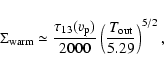
The temperature of the CO emitting layer is significantly higher than
the mean dust temperature ![]() at the same distance: One expects only
at the same distance: One expects only
![]() 30 K at 40
30 K at 40
![]() from both stellar illumination and
accretion (Chiang & Goldreich 1997; D'Alessio et al. 1999). A low value of
from both stellar illumination and
accretion (Chiang & Goldreich 1997; D'Alessio et al. 1999). A low value of
![]() 25 K is independently indicated by fits to the infrared SED of
RW Aur A, which yield
25 K is independently indicated by fits to the infrared SED of
RW Aur A, which yield
![]() (Osterloh & Beckwith 1995).
Hence, the RW Aur A CO disk provides evidence for a gas temperature
increase in the upper disk atmosphere. Indications of increased gas
temperature in upper disk layers were already inferred by
Dartois et al. (2003) in the context of the DM Tau disk, from comparison
of lines from various isotopologues of CO. The RW Aur A observations
probe even higher CO temperatures than in DM Tau and other
previously studied TTS disks, with the possible exception of BP Tau
(where T(CO)
(Osterloh & Beckwith 1995).
Hence, the RW Aur A CO disk provides evidence for a gas temperature
increase in the upper disk atmosphere. Indications of increased gas
temperature in upper disk layers were already inferred by
Dartois et al. (2003) in the context of the DM Tau disk, from comparison
of lines from various isotopologues of CO. The RW Aur A observations
probe even higher CO temperatures than in DM Tau and other
previously studied TTS disks, with the possible exception of BP Tau
(where T(CO) ![]() 50-80 K at 50 AU; Dutrey et al. 2003). This could
result from the unusually small disk radii probed by the present
observations, or from the presence of an additional gas heating
process (see below).
50-80 K at 50 AU; Dutrey et al. 2003). This could
result from the unusually small disk radii probed by the present
observations, or from the presence of an additional gas heating
process (see below).
The fact that the line peaks appear optically thick in
![]() (J=1-0) (see
Sect. 3.2.1) but are not detected in
(J=1-0) (see
Sect. 3.2.1) but are not detected in
![]() (J=1-0), may be used to
constrain the surface density,
(J=1-0), may be used to
constrain the surface density,
![]() ,
of the warm CO emitting layer
near
,
of the warm CO emitting layer
near
![]() .
BS93 find that line opacity does not appear to vary much
with inclination, with face-one and edge-on disks having nearly the
same optical depths (velocity shear roughly compensating for the
increased path-length). We may thus obtain a rough estimate of
.
BS93 find that line opacity does not appear to vary much
with inclination, with face-one and edge-on disks having nearly the
same optical depths (velocity shear roughly compensating for the
increased path-length). We may thus obtain a rough estimate of
![]() using Eq. (12) of BS93 for the pole-on optical depth in
using Eq. (12) of BS93 for the pole-on optical depth in
![]() (J=1-0)
(J=1-0)
 |
(2) |
We concentrate on the blue-shifted peak of the profile, which is not
contaminated by the redshifted arm. There, the upper limit on
![]() (J=1-0)/
(J=1-0)/
![]() (J=1-0)
(J=1-0) ![]() 80/21 indicates
80/21 indicates
![]() .
In the favored case of
.
In the favored case of
![]() ,
where
,
where
![]()
![]() K (see above) we infer
K (see above) we infer
![]() .
Similarly, the fact that
.
Similarly, the fact that
![]() (J=1-0) is optically
thick imposes
(J=1-0) is optically
thick imposes
![]() (assuming a typical abundance of
(assuming a typical abundance of
![]() ), hence
), hence
![]() .
The
approximate range of surface densities for the warm CO layer at
.
The
approximate range of surface densities for the warm CO layer at
![]() is thus
is thus
 |
(3) |
 |
(4) |
 |
(5) |
Note that our observations do not constrain the amount of mass
"hidden'' below the
![]() photosphere, in the colder interior probed
by the dust continuum. Such a cold disk midplane would remain
undetected in
photosphere, in the colder interior probed
by the dust continuum. Such a cold disk midplane would remain
undetected in
![]() (J=1-0), even if optically thick in that line, due
to the intrinsically small disk radius: using Eq. (29) of BS93
one predicts a peak
(J=1-0), even if optically thick in that line, due
to the intrinsically small disk radius: using Eq. (29) of BS93
one predicts a peak
![]() (J=1-0) line flux of 7 mJy only (i.e. our
(J=1-0) line flux of 7 mJy only (i.e. our
![]() level) for a temperature of
level) for a temperature of
![]() =
=
![]() K at
K at
![]() = 40 AU.
= 40 AU.
Interestingly, the column density we infer for the warm CO layer
largely exceeds that of the "superheated'' dust layer in well-mixed
models of illuminated flared disks: a visual opacity
![]() along the slanted path to the star implies a vertical column
density for the superheated layer
along the slanted path to the star implies a vertical column
density for the superheated layer
![]() (Chiang & Goldreich 1997; D'Alessio et al. 1999). One possibility might be that significant
dust settling has occurred, decreasing the visual opacity per unit gas
column and moving the superheated dust layer to
(Chiang & Goldreich 1997; D'Alessio et al. 1999). One possibility might be that significant
dust settling has occurred, decreasing the visual opacity per unit gas
column and moving the superheated dust layer to
![]() .
Evidence for dust settling in the outer regions of CTTS
disks was presented e.g. by Miyake & Nakagawa (1995) based on infrared SED shapes
and by Brittain et al. (2005) from CO absorption measurements in the
HL Tau disk. A second possibility would be that the gas is heated
above the dust equilibrium temperature by strong viscous/turbulent
dissipation above the disk midplane (Glassgold et al. 2004). Such
enhanced dissipation might be related to the strong tidal interaction
suffered by the RW Aur A disk (see next section).
.
Evidence for dust settling in the outer regions of CTTS
disks was presented e.g. by Miyake & Nakagawa (1995) based on infrared SED shapes
and by Brittain et al. (2005) from CO absorption measurements in the
HL Tau disk. A second possibility would be that the gas is heated
above the dust equilibrium temperature by strong viscous/turbulent
dissipation above the disk midplane (Glassgold et al. 2004). Such
enhanced dissipation might be related to the strong tidal interaction
suffered by the RW Aur A disk (see next section).
The redshifted expanding "arm'' is an unusual feature not previously observed in a T Tauri system. Based on its connexion to the RW Aur A disk on the side opposite to RW Aur B, its trailing spiral morphology, and its unbound expanding motions (see Sect. 3.2.3), we propose that it is tracing a tidal tail stripped from the RW Aur A disk by the recent fly-by of RW Aur B. Indeed, simulations of an accretion disk response to a stellar fly-by reproduce remarkably well all of the above properties, provided the companion is on a prograde orbit (see e.g. Fig. 2a of Clarke & Pringle 1993).
In the tidal interaction process, a substantial fraction of the disk mass beyond the truncation radius is ejected in the tidal arm, and a similar fraction is captured by the perturber. The capture process may well be causing the disturbed kinematics and morphology we observe in the RW Aur B molecular peak.
If B were on a circular orbit around A, the expected tidal truncation
limit for the primary disk would be 0.4 of the separation
(Papaloizou & Pringle 1977), i.e. ![]() 80 AU (the projected AB angular separation
is
80 AU (the projected AB angular separation
is
![]() ). The observed disk radius of only 40-57
). The observed disk radius of only 40-57
![]() thus points to an eccentric orbit for B. The results of
Artymowicz & Lubow (1994) for eccentric systems indicate that the primary
disk will be truncated at
thus points to an eccentric orbit for B. The results of
Artymowicz & Lubow (1994) for eccentric systems indicate that the primary
disk will be truncated at
![]() ,
where
p = (1-e)a is
the periastron, for a typical disk viscosity parameter
,
where
p = (1-e)a is
the periastron, for a typical disk viscosity parameter
![]() and a mass parameter
and a mass parameter
![]() appropriate to
RW Aur . We thus estimate
appropriate to
RW Aur . We thus estimate
![]() .
.
It is tempting to speculate that the strong tidal interaction we are witnessing might also solve a long standing puzzle, namely how RW Aur A can maintain such a high accretion rate, despite a small disk mass and the lack of ambient cloud reservoir. Indeed, SPH simulations have suggested that dissipation associated with tidal stripping could trigger a transient accretion outburst onto the stars (Bonnell & Bastien 1992). Then, the current accretion rate in RW Aur A would not be representative of the mean level, and the disk lifetime would be much longer than previously thought. Specific conditions need to be met, however, to prevent the tidally-induced density and bending waves from damping before reaching the inner disk (see e.g. Terquem 2000, and references therein).
An important result of our observations concerning the issue of jet
launching is that the rotation sense of the Keplerian disk around
RW Aur A is opposite to that inferred for its optical jet by
Woitas et al. (2005): the latter authors find that "the sense of
rotation [of the jet] is anti-clockwise looking from the tip of the
blue lobe down to the star''. As can be seen in
Fig. 3, the CO disk rotates in the clockwise
direction when viewed from the tip of the blue lobe (in other words,
the rotation vector
![]() points towards the red-shifted jet
lobe). As argued above, we are confident that the observed CO disk
velocity gradient is reliable and is not an artifact, since (1) the
data quality is excellent, (2) the gradient direction is exactly
perpendicular to the jet axis (Fig. 1c), an
unambiguous sign of disk rotation, (3) the emission is point-symmetric in space and velocity with respect to RW Aur A
(Fig. 3).
points towards the red-shifted jet
lobe). As argued above, we are confident that the observed CO disk
velocity gradient is reliable and is not an artifact, since (1) the
data quality is excellent, (2) the gradient direction is exactly
perpendicular to the jet axis (Fig. 1c), an
unambiguous sign of disk rotation, (3) the emission is point-symmetric in space and velocity with respect to RW Aur A
(Fig. 3).
MHD disk winds, where enthalpy is negligible in matter acceleration, are necessarily rotating in the same sense as the underlying disk at the launch point (Anderson et al. 2003, their Eq. (4)). Therefore this discrepancy is quite puzzling. Even though the RW Aur A disk is clearly tidally disturbed, it is very difficult to envision a process that would make it counter-rotate with respect to inner disk regions (from where the jet originates). In particular, models of disk dynamics in eccentric systems show that the orbit of RW Aur B must be prograde to produce the strong tidal arm that is observed (Clarke & Pringle 1993). Therefore, the fly-by of RW Aur B cannot have reverted the rotation sense of the outer disk with respect to the inner disk.
At this stage, the simplest explanation would appear to be that
the transverse centroid velocity shifts currently measured in the
RW Aur optical jet are dominated by other effects than jet
rotation. For example, recent simulations show that a precessing,
time-variable jet produces transverse shifts that may mimic jet rotation
(Cerqueira et al. 2006). The jet rotation speeds and the launch radii of
0.5-1.6
![]() inferred by Woitas et al. (2005) would then be upper limits
only.
inferred by Woitas et al. (2005) would then be upper limits
only.
We stress that this does not rule out altogether an MHD disk wind
origin for the optical jet of RW Aur A: the theoretical model of disk
wind that best fits the DG Tau jet rotation data, with a magnetic
lever arm parameter
![]() (Pesenti et al. 2004),
predicts rotation velocities for the RW Aur jet that lie below these
upper limits (Ferreira et al. 2006). Optical observations at higher
spatial and spectral resolution, probing more axial jet regions, are
needed to fully test the disk wind model in this object.
(Pesenti et al. 2004),
predicts rotation velocities for the RW Aur jet that lie below these
upper limits (Ferreira et al. 2006). Optical observations at higher
spatial and spectral resolution, probing more axial jet regions, are
needed to fully test the disk wind model in this object.
Another result of our observations related to disk winds is the lack
of a detectable molecular counterpart to the RW Aur A atomic
jet. Scaling from the DG Tau jet (Pesenti et al. 2004) one would expect
material launched from disk radii of 1 to 40
![]() to reach poloidal
speeds in the range
to reach poloidal
speeds in the range
![]()
![]() within 50 AU of the
star. No signal was found in this velocity range, even in 3.5
within 50 AU of the
star. No signal was found in this velocity range, even in 3.5
![]() wide channels, down to 18 mJy (
wide channels, down to 18 mJy (![]() ). This limit corresponds to a
gas mass per unit velocity of
). This limit corresponds to a
gas mass per unit velocity of
![]() per
per
![]() (assuming a standard CO abundance and LTE).
(assuming a standard CO abundance and LTE).
Self-similar MHD disk wind models predict that in each jet lobe
![]() ,
where
,
where
![]() is the ejection index and
is the ejection index and
![]() is the
beam radius (centered on the star). Taking
is the
beam radius (centered on the star). Taking
![]()
![]() ,
,
![]() =
0.36'' = 50
=
0.36'' = 50
![]() ,
and
,
and
![]() (Pesenti et al. 2004), we infer
(Pesenti et al. 2004), we infer
![]() per
per
![]() .
Thus, our non detection in CO does not rule out molecular
MHD ejection from disk radii beyond 1 AU if the molecular jet is
hotter than
.
Thus, our non detection in CO does not rule out molecular
MHD ejection from disk radii beyond 1 AU if the molecular jet is
hotter than
![]() (e.g. due to X-rays or ambipolar
diffusion heating). Rotational or rovibrational H2 emission would
then be a better tracer.
(e.g. due to X-rays or ambipolar
diffusion heating). Rotational or rovibrational H2 emission would
then be a better tracer.
Our main results and implications are the following:
Acknowledgements
We acknowledge the IRAM staff at Plateau de Bure and Grenoble for carrying out the observations and for the help provided during the data reduction. We also thank I. Bonnell, F. Gueth, F. Ménard, C. Terquem and an anonymous referee for helpful comments on this paper, and A. Dutrey and V. Piétu for the communication of their flux measurements. This research is supported by the JETSET Marie Curie Research and Training Network as part of the European Community's Human Potential Programme, under contract MRTN-CT-2004-005592.
![\begin{figure}
\par\includegraphics[angle=270,width=13.5cm,clip]{4047fa1.eps} \end{figure}](/articles/aa/full/2006/24/aa4047-05/img203.gif) |
Figure A.1:
Channel maps of
|