A&A 445, 779-794 (2006)
DOI: 10.1051/0004-6361:20053040
P. K. Fung1 - D. Khechinashvili2,3 - J. Kuijpers2
1 - Astronomical Institute,
Utrecht University, PO Box 80000, 3508 TA Utrecht, The
Netherlands
2 - Department of Astrophysics, IMAPP, Radboud
University Nijmegen, PO Box 9010, 6500 GL Nijmegen, The
Netherlands
3 - Centre for Plasma Astrophysics, K. U. Leuven,
Celestijnenlaan 200B, 3001 Leuven, Belgium; on leave for
Institute of Astronomy, University of Zielena Góra, Lubuska 2,
65-265, Zielena Góra, Poland / Astrophysical Observatory, Al.
Kazbegi ave. 2a, Tbilisi 0160, Georgia
Received 10 March 2005 / Accepted 12 July 2005
Abstract
The potential
role of a diocotron instability in causing drifting sub-pulses in
radio pulsar emission is investigated for aligned magnetic
rotators. It is assumed that the out-flowing plasma above a pulsar
polar cap consists of an initially axially symmetric, hollow beam
of relativistic electron positron pair plasma which carries an
electric charge as well as a current. The occurrence of
instability depends on shear in the angular velocity distribution
of the beam as a function of axial distance. Instability occurs
under typical pulsar conditions at mode numbers ![]() 40. It
destroys the symmetry of the equilibrium configuration and leads
to a carousel of density columns which rotates at fixed angular
pattern speed. The process is applied to two pulsars with observed
carousels of drifting sub-pulses, and the diocotron instability at
corresponding mode number and axial distance is used as a
diagnostic for the charge and current density of the polar flow.
40. It
destroys the symmetry of the equilibrium configuration and leads
to a carousel of density columns which rotates at fixed angular
pattern speed. The process is applied to two pulsars with observed
carousels of drifting sub-pulses, and the diocotron instability at
corresponding mode number and axial distance is used as a
diagnostic for the charge and current density of the polar flow.
Key words: stars: pulsars: general - plasmas - magnetohydrodynamics (MHD) - instabilities
Although radio pulsars have been observed for more than
thirty-five years, our understanding of the emission process
remains poor. The radiation is observed to have a high brightness
temperature (Melrose 1995) and is believed to be emitted
tangentially to open magnetic field lines above the neutron star's
polar caps, somewhere between the stellar surface and the light
cylinder. As the star rotates, the magnetic pole sweeps past our
line of sight and we receive a radio pulse. The temporal structure
of the observed pulse corresponds to the spatiotemporal emission
along the strip cut out by our line of sight. The radio emission
is probably generated by relativistic particles streaming out
along the open field lines, but the precise physical conditions
under which the radiation is produced, and the precise location of
the emission region above the rotating neutron star, remain
obscure. The most remarkable feature of the pulsar is the
stability of the pulse profile when averaged over about a hundred
subsequent pulses, whereas individual pulses are complex and
highly variable. An individual pulse is built out of sub-pulses
and sometimes micro-pulses of
![]() s duration. In a
number of "ordinary'' (i.e., excluding millisecond) pulsars drifting sub-pulses have been observed which show a remarkable
drift stability. It now appears that the occurrence of drifting
sub-pulses is not a rare phenomenon but can be detected in half of
the radio pulsars (Weltevrede et al. 2005; Ashworth 1981). Drifting
sub-pulses are sub-pulses that drift in longitude from pulse to
pulse at a nearly constant rate. For some pulsars, a "carousel''
model can be constructed, which consists of emission columns
arranged along a circle centered at the stellar magnetic axis,
which sub-rotate with respect to the star (Deshpande & Rankin 1999,2001).
Understanding drifting sub-pulses is probably of critical
importance for our understanding of the pulsar electrodynamics and
pulsar emission mechanism.
s duration. In a
number of "ordinary'' (i.e., excluding millisecond) pulsars drifting sub-pulses have been observed which show a remarkable
drift stability. It now appears that the occurrence of drifting
sub-pulses is not a rare phenomenon but can be detected in half of
the radio pulsars (Weltevrede et al. 2005; Ashworth 1981). Drifting
sub-pulses are sub-pulses that drift in longitude from pulse to
pulse at a nearly constant rate. For some pulsars, a "carousel''
model can be constructed, which consists of emission columns
arranged along a circle centered at the stellar magnetic axis,
which sub-rotate with respect to the star (Deshpande & Rankin 1999,2001).
Understanding drifting sub-pulses is probably of critical
importance for our understanding of the pulsar electrodynamics and
pulsar emission mechanism.
To date, several models have been proposed to explain this
phenomenon. In the model by Ruderman & Sutherland (1975, hereafter RS75),
drifting sub-pulses are interpreted in terms of spark-associated
plasma columns rotating around the magnetic axis due to the
![]() -drift, where
-drift, where ![]() is the background
magnetic field and
is the background
magnetic field and ![]() is the electric field in the frame
corotating with the star. The assumption of the infinitely large
binding energy of ions in the stellar surface, crucial for the
spark model, has been severely criticized by several authors
(see, e.g., Neuhauser et al. 1987,1986). Moreover, there is strong
disagreement between the observed drift speed and the one
predicted by the spark model (as shown by van Leeuwen et al. 2003, in the case of
PSR B0809+74). In the model by Gil et al. (2003) the
vacuum gap is partially screened due to thermionic emission of
ions/electrons, and sparks still occur but at a smaller drift
rate.
is the electric field in the frame
corotating with the star. The assumption of the infinitely large
binding energy of ions in the stellar surface, crucial for the
spark model, has been severely criticized by several authors
(see, e.g., Neuhauser et al. 1987,1986). Moreover, there is strong
disagreement between the observed drift speed and the one
predicted by the spark model (as shown by van Leeuwen et al. 2003, in the case of
PSR B0809+74). In the model by Gil et al. (2003) the
vacuum gap is partially screened due to thermionic emission of
ions/electrons, and sparks still occur but at a smaller drift
rate.
Another model (Clemens & Rosen 2004) ascribes the drifting sub-pulses to
non-radial pulsations of the neutron star. A difficulty with this
model is the exclusive selection of one particular high-order
spherical eigenmode (with a spherical harmonic numbers in between
![]() and m=0) at the stellar surface. Also,
there is no clear link of the internal oscillations of the star to
the processes leading to generation of radio emission higher above
the stellar surface. Alternatively, Kazbegi et al. (1991) explain the
sub-pulse drift in terms of modulation of the emission region by
large-scale "drift waves'', which alter the local curvature of the
magnetic field lines and thus affect strongly the occurrence of
the Cherenkov-drift resonance - a main mechanism of generation of
pulsar radio emission, according to Kazbegi et al. (1991). A recent
revised version of this model, by Gogoberidze et al. (2005), favours
modulation either through modification of the distribution
function of particles by the drift wave electric field, or through
changes in the emission angle. The stability of a distinct drift
pattern is achieved by the accumulation of the drift modes in a
specific azimuthal eigenmode, resulting from their non-linear
evolution. The model requires relatively weak magnetic field
values, which prevail at distances corresponding to a significant
fraction of the light cylinder radius while observations suggest
that the emission processes take place at much closer distances to
the pulsar surface, typically 50-100 stellar radii (see,
e.g., Kijak & Gil 2003). Finally, a recent empirical model constructed by
Wright (2003) attributes the formation of a drifting regular
pattern of emission nodes to constructive interaction between
electron and positron beams traveling, respectively, up and down
in the magnetosphere, between inner and outer acceleration gaps.
The model, though, does not elaborate on the detailed
electrodynamics.
and m=0) at the stellar surface. Also,
there is no clear link of the internal oscillations of the star to
the processes leading to generation of radio emission higher above
the stellar surface. Alternatively, Kazbegi et al. (1991) explain the
sub-pulse drift in terms of modulation of the emission region by
large-scale "drift waves'', which alter the local curvature of the
magnetic field lines and thus affect strongly the occurrence of
the Cherenkov-drift resonance - a main mechanism of generation of
pulsar radio emission, according to Kazbegi et al. (1991). A recent
revised version of this model, by Gogoberidze et al. (2005), favours
modulation either through modification of the distribution
function of particles by the drift wave electric field, or through
changes in the emission angle. The stability of a distinct drift
pattern is achieved by the accumulation of the drift modes in a
specific azimuthal eigenmode, resulting from their non-linear
evolution. The model requires relatively weak magnetic field
values, which prevail at distances corresponding to a significant
fraction of the light cylinder radius while observations suggest
that the emission processes take place at much closer distances to
the pulsar surface, typically 50-100 stellar radii (see,
e.g., Kijak & Gil 2003). Finally, a recent empirical model constructed by
Wright (2003) attributes the formation of a drifting regular
pattern of emission nodes to constructive interaction between
electron and positron beams traveling, respectively, up and down
in the magnetosphere, between inner and outer acceleration gaps.
The model, though, does not elaborate on the detailed
electrodynamics.
Here, the proposed explanation of drifting sub-pulses is the
occurrence of a diocotron instability (also known as "rotational
shear'' or "slipping stream'' instability) in the pair plasma on the
open pulsar field lines. The diocotron instability is an
instability of a sheared flow, much like the familiar
Kelvin-Helmholtz instability in a quasi-neutral plasma, now,
however, in a non-neutral plasma, which is why it is sometimes
also called the "electrostatic'' Kelvin-Helmholtz instability
(Hasegawa 1975). Specifically, the diocotron instability occurs in a
charged plasma beam along a uniform background magnetic field and
a vanishing background electric field component parallel to the
background magnetic field (e.g., Davidson 1974, Sect. 2.10). The electric self-field of the charged beam
would lead to the familiar
![]() drift around
the cylinder axis which is now, however, modified by the effect of
a magnetic self-field from the beam which, in general, carries an
electric current as well as a charge. When the resulting
differential rotation of the beam around the cylinder axis
satisfies a certain condition, a non-axially symmetric
perturbation in density, velocity and electric potential can grow
over the shear layer. To linear order, the unstable surface modes
are characterized by a radial eigenfunction, an azimuthal mode
number l, an axial wave-number
drift around
the cylinder axis which is now, however, modified by the effect of
a magnetic self-field from the beam which, in general, carries an
electric current as well as a charge. When the resulting
differential rotation of the beam around the cylinder axis
satisfies a certain condition, a non-axially symmetric
perturbation in density, velocity and electric potential can grow
over the shear layer. To linear order, the unstable surface modes
are characterized by a radial eigenfunction, an azimuthal mode
number l, an axial wave-number
![]() ,
and an angular
frequency
,
and an angular
frequency ![]() ,
whose imaginary part gives the growth rate
,
whose imaginary part gives the growth rate
![]() and whose real part is related to
the angular pattern speed through
and whose real part is related to
the angular pattern speed through
![]() .
It is this angular pattern speed which
we identify with the rotation speed of the drifting sub-pulses
when viewed from the lab frame.
.
It is this angular pattern speed which
we identify with the rotation speed of the drifting sub-pulses
when viewed from the lab frame.
In this paper we model the plasma outflow above the pair-creation
front as an infinitely long, non-neutral annular beam composed of
electrons and positrons propagating with relativistic speeds along
the pulsar's magnetic field. Stability analysis reveals a
large domain of realistic parameters, where the - linear stage of
- diocotron instability may indeed occur under pulsar
magnetospheric conditions.
We assume
that l and
![]() of the unstable mode can be
linked to the observed number of sub-beams and pattern circulation
time
of the unstable mode can be
linked to the observed number of sub-beams and pattern circulation
time
![]() ,
where
,
where
![]() is the
pulsar rotation frequency and
is the
pulsar rotation frequency and
![]() is measured in
units of pulsar periods P1. Using these two assumptions, we
then apply our model to the two pulsars with the best
studied carousel patterns, viz. PSRs B0943+10 and B0826-34, and
demonstrate that the the model is able to account in a
natural way for the basic properties of the drift patterns observed in these pulsars.
Furthermore, the model can explain drift direction reversals as in PSR B0826-34. For the relativistic beam to nearly corotate
(only slightly sub-rotate) with the star, the model requires
the charge difference in the beam to exceed
the Goldreich-Julian charge density (Goldreich & Julian 1969; see also Eq. (1) below) many times, which is no problem for a typical pair plasma.
is measured in
units of pulsar periods P1. Using these two assumptions, we
then apply our model to the two pulsars with the best
studied carousel patterns, viz. PSRs B0943+10 and B0826-34, and
demonstrate that the the model is able to account in a
natural way for the basic properties of the drift patterns observed in these pulsars.
Furthermore, the model can explain drift direction reversals as in PSR B0826-34. For the relativistic beam to nearly corotate
(only slightly sub-rotate) with the star, the model requires
the charge difference in the beam to exceed
the Goldreich-Julian charge density (Goldreich & Julian 1969; see also Eq. (1) below) many times, which is no problem for a typical pair plasma.
A similar instability, namely an electrostatic shear flow
instability, has been studied before in the context of pulsar
magnetospheres by Arons & Smith (1979). Although the authors state that
their basic equations contain also the physics of other
instabilities, including the diocotron instability, they do not
treat the latter process, but rather concentrate on implications
of the shear in parallel relativistic momentum. The modes excited
due to such a shear are space charge waves, contrasting with the
diocotron surface modes, treated in the present paper and leading
to azimuthal fragmentation of the flow. It is also important to
notice that Arons & Smith (1979) assume a small perturbation wavelength
along the external magnetic field, whereas our approximation is
just the opposite to that (i.e., we have
![]() ). In
addition, Arons & Smith (1979) only found the electrostatic shear flow
instability to appear at enormously large azimuthal wave-numbers
(l > 107). We find the same to be true for the diocotron
instability if one assumes that the flow is charge-separated, as
in Arons & Smith (1979). However, here we will show that the diocotron
instability can operate in a relativistic beam under pulsar
conditions if the density distribution is not charge-separated,
but instead is formed by a pair plasma.
). In
addition, Arons & Smith (1979) only found the electrostatic shear flow
instability to appear at enormously large azimuthal wave-numbers
(l > 107). We find the same to be true for the diocotron
instability if one assumes that the flow is charge-separated, as
in Arons & Smith (1979). However, here we will show that the diocotron
instability can operate in a relativistic beam under pulsar
conditions if the density distribution is not charge-separated,
but instead is formed by a pair plasma.
In Sect. 2 we provide the physical background for the inner magnetosphere and describe a beam model with a minimum amount of detail but which does contain the essence of the various existing theories on pulsar electrodynamics. The diocotron instability of the beam is then investigated in a fluid approach and the analytical results are presented in Sect. 3 while the derivation is given in the Appendix. Numerical results on the instability, the pattern speed, and the growth rate for various choices in parameter space are presented in Sect. 4. The implications for pulsars and the observed drifting sub-pulses are given in Sect. 5. We end with a discussion and conclusions in Sect. 6. We use SI units throughout the paper.
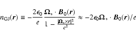
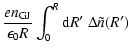
In order to study the physics of the diocotron instability and construct a correct model of the non-neutral pair plasma beam, one should first understand the electrodynamics of the pulsar magnetosphere. Here, after brief review of existing magnetospheric theories, we discuss the nature of the "rotational'' drift in pulsars, in case of both aligned and inclined pulsars. As we will show by simple reasoning, the assumption of independence of the current and charge densities from each other is essential for "near-corotation'' of the open magnetic flux tube with the pulsar.
Most pulsar theories have in common the existence of a corotating closed
magnetosphere and two bundles of "open'' field lines defining the polar
caps on the stellar surface and passing through the light
cylinder. Everywhere in the corotating magnetosphere the plasma is
charge separated - it consists of one kind of charge only - and
the charge density is given by the Goldreich-Julian density
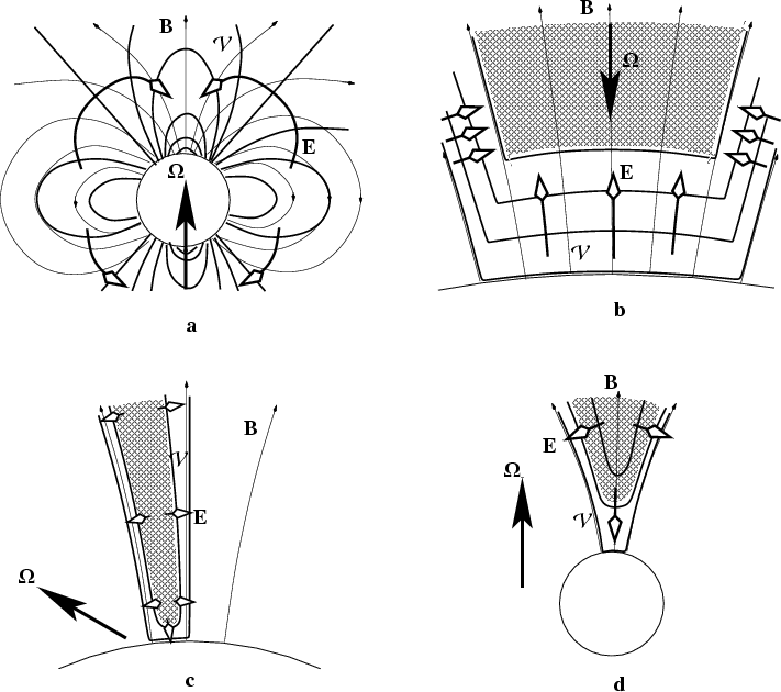 |
Figure 1:
Sketch of
various models for pair creation (hatched) on the open field lines
|
The field lines on the magnetic flux surface separating the
incoming and the outgoing current are called the critical
field lines by Goldreich & Julian (1969). The critical field lines are at the
same electric potential as the interstellar medium. A simple
estimate of their position on the polar cap can be obtained if one
assumes that all over the polar cap the current density is just
the Goldreich-Julian density at the stellar surface multiplied
with - or + the speed of light depending on whether the
current comes in or goes out. The feet of the critical field lines
are then positioned at an angle
![]() as seen from the
stellar center given by
as seen from the
stellar center given by
![]() which differs only by a factor
0.96 from the feet of the field lines which pass through the
cross-section of both the light cylinder and the null lines, and
which are located at an angle
which differs only by a factor
0.96 from the feet of the field lines which pass through the
cross-section of both the light cylinder and the null lines, and
which are located at an angle
![]() at
the stellar surface. It is interesting to note that the latter
field lines define the outer emission cone in Wright (2003).
at
the stellar surface. It is interesting to note that the latter
field lines define the outer emission cone in Wright (2003).
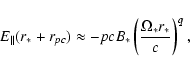
The field in the rupture zone near the foot-points is of
course not frozen into the plasma. Far above the acceleration
region, the situation becomes practically independent of altitude
and the electric field is entirely due to space charges inside the
beam and not to any surface-charges as is the case near the
stellar surface. In the RS75 model, such would apply already at a
distance of a few polar cap radii above the surface while in the
general relativistic model of Muslimov & Tsygan (1992) this would apply
above a few stellar radii. Since we are interested in the drift
motion of a relativistic plasma beam - which creates its own
transverse magnetic field
![]() - the drift motion of
the plasma as obtained from the approximate force equilibrium
condition
- the drift motion of
the plasma as obtained from the approximate force equilibrium
condition
![]() is given by:
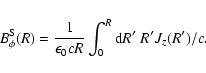
is given by:
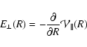
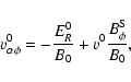
As to whether the magnetic field is strong enough to enforce corotation of any plasma with the stellar rotation, the answer depends on the global distribution of electric fields. If there is no potential drop between the stellar surface and a relativistic plasma beam higher up then in a Poynting-flux dominated situation, as is the case for the pulsar, the beam would corotate with the star. The required relatively strong electric field would simply be given by a strong super Goldreich-Julian density. But in a realistic pulsar, the relativistic nature of the beam is caused by a parallel voltage drop that allows for rupture of the magnetic field lines below the beam and may cause a strong sub-rotation of the beam with respect to the stellar rotation.
To study the diocotron instability, the relativistic macroscopic
fluid
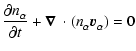
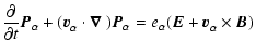
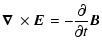
description is used. Each species ![]() is described by the coupled fluid-Maxwell's equations:
is described by the coupled fluid-Maxwell's equations:
| (14) | |||
| (15) |
The stability of the equilibrium under electrostatic perturbations
is investigated where each quantity is perturbed as follows:
 |
(16) |
The surface waves are the solution of the linearized fluid-Maxwell equations. Before we analyze the equilibrium situation and the solution of the perturbed system, we first describe the geometry of the charged beam, because the assumptions we make enable us to simplify the set of equations.
We consider three possible geometries: a hollow beam, a hollow beam including a core component, and a hollow beam in which the current reverses sign.
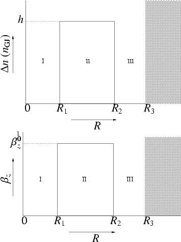
As a first simple case, we model the beam in this paper as a
hollow beam of electrons and positrons with nearly equal axial
velocities (Fig. 5). The densities of electrons
and positrons are assumed to be constant in different regions of
the beam. Then, only the density difference
![]() is relevant and is taken to be
different only in region II. We normalize
is relevant and is taken to be
different only in region II. We normalize
![]() where
where
![]() is not the GJ-density
Eq. (1) but an abbreviation involving the absolute value
of the local magnetic field strength B0:
is not the GJ-density
Eq. (1) but an abbreviation involving the absolute value
of the local magnetic field strength B0:
 |
(17) |
For the motion of the two species, we take
![]() independent of R. Additionally, particles are
only relativistic in the axial direction, so that
independent of R. Additionally, particles are
only relativistic in the axial direction, so that
![]() .
We express the axial current density
of the beam formally as
.
We express the axial current density
of the beam formally as
Two additional configurations are examined: the influence of a nonzero core and when part of the beam moves in the opposite direction (return current).
In Fig. 6 the model including a nonzero core is
presented. The charge density difference in region I is
![]() .
We expect that in this region no pair creation
occurs because of the large radius of curvature of the magnetic
field, and, therefore, that the beam is charge-separated. The
axial velocity remains unchanged, i.e. both in region I and in
region II, approximately the same axial velocity applies to all
particles.
.
We expect that in this region no pair creation
occurs because of the large radius of curvature of the magnetic
field, and, therefore, that the beam is charge-separated. The
axial velocity remains unchanged, i.e. both in region I and in
region II, approximately the same axial velocity applies to all
particles.
As for the return current, the axial velocity of the hollow beam
changes sign at the radial location
| |
Figure 6:
Similar to
Fig. 5; now, a core component is included. The
dimensionless charge difference in Region I is |
 |
Figure 7: Similar to Fig. 5, but now, part of the beam moves in the opposite direction (Rp is defined by Eq. (19)). |
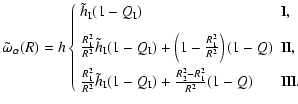
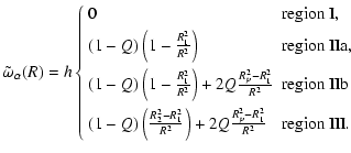
If one neglects the first term one immediately derives the earlier
result
![]() (cf. Eq. (7)). Actually,
the first term represents the inertial acceleration which can be
neglected even for large Lorentz factors because of the strength
of the background magnetic field. Defining
(cf. Eq. (7)). Actually,
the first term represents the inertial acceleration which can be
neglected even for large Lorentz factors because of the strength
of the background magnetic field. Defining
![]() ,
,
![]() and
and
![]() ,
the angular
rotational velocity
,
the angular
rotational velocity
![]() for the hollow beam
(Fig. 5) reads:
for the hollow beam
(Fig. 5) reads:
For illustrative purposes, the rotational velocities for the cases
(24) to (26) with R1 = 0.3, R2 =
0.6 and R3 = 1 are shown in Fig. 8:
hollow beam with Q = 0 (solid), hollow beam with Q= 0.5 (long
dash), beam with core (
![]() )
and Q = 0.5 (short dash) and beam including return current with
Q= 0.5 where Rp is determined by zero ring
current (Eq. (20), dotted) and another where p = 0.5(dash-dotted). Note that the presence of a return current in a
relativistic beam has the effect of pushing up the rotational
velocity toward corotation (compare dotted and long-dashed
solutions).
)
and Q = 0.5 (short dash) and beam including return current with
Q= 0.5 where Rp is determined by zero ring
current (Eq. (20), dotted) and another where p = 0.5(dash-dotted). Note that the presence of a return current in a
relativistic beam has the effect of pushing up the rotational
velocity toward corotation (compare dotted and long-dashed
solutions).
![\begin{figure}
\par\includegraphics[width=7.1cm,clip]{3040f8.eps}\end{figure}](/articles/aa/full/2006/03/aa3040-05/img136.gif) |
Figure 8: Examples of equilibrium rotational velocity distributions across the beam, where R1,R2 are the inner and outer boundary of the beam. See text for the cases and the beam parameters. |
Linearizing the fluid-Maxwell's equations is done by assuming that
the perturbations are electrostatic, i.e.
![]() is small
compared to
is small
compared to
![]() in the momentum equation and Faraday's law.
With this, the perturbed electric field can be described as the
gradient of a scalar potential:
in the momentum equation and Faraday's law.
With this, the perturbed electric field can be described as the
gradient of a scalar potential:
Now, since we are using step-functions for ![]() ,
Eq. (29) can be solved analytically. This applies
even in the case of a "return current'', because in the derivation
of Eq. (29) we have neglected the contributions of
kz and
,
Eq. (29) can be solved analytically. This applies
even in the case of a "return current'', because in the derivation
of Eq. (29) we have neglected the contributions of
kz and
![]() .
.
The general solution of
Eq. (29) for our model, is given by:
![\begin{figure}
\par\includegraphics[width=7cm,clip]{3040f9.eps}\end{figure}](/articles/aa/full/2006/03/aa3040-05/img180.gif) |
Figure 9:
Equipotential for annular beam with Q = 0, R1 = 0.5,
R2 = 0.6 and l = 5 at t = 0. Black areas denote negatively
valued |
Obviously, extremes are formed at the two surfaces with five
azimuthal modes. Moreover, the surface waves are shifted in phase
with respect to each other. To demonstrated this, we use the
expression for the perturbed potential at the surfaces
Eq. (30), but now, C1/C2 is given by:
 |
(37) |
![\begin{displaymath}\frac{\tilde{V}(R_2)}{\tilde{V}(R_1)} = (R_1/R_2)^{-l} +
\exp[-i\phi']\frac{(R_1/R_2)^{l} - (R_1/R_2)^{-l}}{\sqrt{G_2}}
\end{displaymath}](/articles/aa/full/2006/03/aa3040-05/img182.gif) |
(38) |
![\begin{figure}
\mbox{%
\par\includegraphics[width=5.6cm]{3040f10a.eps}\hskip1.7c...
...10e.eps}\hskip1.7cm
\includegraphics[width=5.6cm]{3040f10f.eps}\\ }
\end{figure}](/articles/aa/full/2006/03/aa3040-05/img186.gif) |
Figure 10:
Left: unstable diocotron modes in the parameter
space of R1/R3 (along the horizontal axis) and R2/R3(along the vertical axis). In levels of grey is plotted
|
![\begin{figure}
\mbox{%
\par\includegraphics[width=5.6cm]{3040f11a.eps}\hskip1.7c...
...11e.eps}\hskip1.7cm
\includegraphics[width=5.6cm]{3040f11f.eps}\\ }
\end{figure}](/articles/aa/full/2006/03/aa3040-05/img188.gif) |
Figure 11:
The same as in Fig. 10, but now including
a charge-separated core in Region I (see Eq. (25) and
Fig. 6). The corresponding value of
|
![\begin{figure}
\mbox{%
\par\includegraphics[width=5.6cm]{3040f12a.eps}\hskip2cm
...
...040f12c.eps}\hskip2cm
\includegraphics[width=5.6cm]{3040f12d.eps} }
\end{figure}](/articles/aa/full/2006/03/aa3040-05/img189.gif) |
Figure 12: The same as in the left column of Fig. 10, but now including a return current (see Eq. (26) and Fig. 7). Above each graph are seen the corresponding parameters Q and p, the latter defining Rp, i.e. the radius where the axial velocity of the beam particles changes sign (see Eq. (19)). |
![\begin{figure}
\mbox{%
\par\includegraphics[width=5.6cm]{3040f13a.eps}\hskip2cm
...
...040f13c.eps}\hskip2cm
\includegraphics[width=5.6cm]{3040f13d.eps} }
\end{figure}](/articles/aa/full/2006/03/aa3040-05/img190.gif) |
Figure 13: Maximum growth rate (squares) and pattern velocities (triangles) corresponding to the case in Fig. 12. |
Thus, in general, the two waves are shifted in phase, which is determined by the geometry. Due to the shift, the two surface waves are coupled to each other through their perturbed potential. To be more specific, under the condition determined by Eq. (34), perturbations at the outer surface can influence the perturbations at the inner surface, and vice versa, leading to exponential growth.
It is this system that probably will evolve into a non-linear stage where particles are trapped and vortices form.
For a hollow beam, in which Q ranges from 0 to 0.8 in steps of
0.2,
![]() is presented in Fig. 10. In the
case of Q = 0 (i.e. either the beam is nonrelativistic or the
beam carries no current), the beam displays instability for all
modes. The general trend for all
Q's is that thinner beams, i.e.
is presented in Fig. 10. In the
case of Q = 0 (i.e. either the beam is nonrelativistic or the
beam carries no current), the beam displays instability for all
modes. The general trend for all
Q's is that thinner beams, i.e.
![]() ,
are unstable for higher l.
,
are unstable for higher l.
An increase in Q leads to a shift of the
![]() regions in parameter space and a decrease in their area, until,
for small
regions in parameter space and a decrease in their area, until,
for small
![]() ,
instability eventually vanishes. In
the case of Q = 0.9, almost any hollow beam is stable and
therefore, the corresponding parameterspace is not presented. This
is in agreement with the results of Arons & Smith (1979) for a
charge-separated, relativistic, particle beam. In that case: fequals h, the first term for both G1 and G2 becomes negligible
when we assume
,
instability eventually vanishes. In
the case of Q = 0.9, almost any hollow beam is stable and
therefore, the corresponding parameterspace is not presented. This
is in agreement with the results of Arons & Smith (1979) for a
charge-separated, relativistic, particle beam. In that case: fequals h, the first term for both G1 and G2 becomes negligible
when we assume
![]() ,
and solutions for
,
and solutions for
![]() are very stable unless
are very stable unless
![]() (see Eqs. (33) and (34)).
(see Eqs. (33) and (34)).
Figure 11 depicts the influence of adding a charge
separated core component by increasing
![]() in
steps from 0.1 to 0.9 (in region II: Q = 0.4). Since it is
charge separated, we have
in
steps from 0.1 to 0.9 (in region II: Q = 0.4). Since it is
charge separated, we have
![]() .
Clearly, when
.
Clearly, when
![]() the shear is still present (see
Eq. (25)) and we observe a diocotron instability.
the shear is still present (see
Eq. (25)) and we observe a diocotron instability.
In Figs. 12 and 13 is shown the effect of a return current on the occurence of instability. In the case where Rp is determined by the condition that the net ring current is zero, the rotational velocities at R1 and R2are identical to those of Q=0 in the hollow beam case. Since the instability condition depends only on these velocities (Eqs. (31)-(34)) there is no need to locate the unstable domains in the parameter space again.
The data available from the literature is shown in Table 1.
| PSR |
|
|
P1(s) | P3 (P1) | l |
|
|
| B0943+10 (Deshpande & Rankin 2001) | 11.58 | -4.29 | 1.09 | 1.87 | 20 | 37 | 0.973 |
| B0826-34 (Gupta et al. 2004) | 1-2 | 1 | 1.848 | 0.50 | 15 | 7.5 | 0.833 |
| B0826-34 (Esamdin et al. 2005) | 0.5 | - | 1.848 | {+6, -7} | 13 | +78, -91 | { 0.99, 1.01} |
For
R1/R3 = 0.65 and
R2/R3 = 0.92, we calculate
![]() in the parameterspace (l, Q) (see
Fig. 14). Apparently, growth rate is not at optimum for
l = 20. Since we do not have more information on Q, we conclude
that for l = 20 to develop, we need
in the parameterspace (l, Q) (see
Fig. 14). Apparently, growth rate is not at optimum for
l = 20. Since we do not have more information on Q, we conclude
that for l = 20 to develop, we need
![]() .
By combining
this with measured
.
By combining
this with measured
![]() ,
we find
from Eq. (36) that
,
we find
from Eq. (36) that
![]() .
.
Since the values for R1/R3 and R2/R3 are just estimations,
it is important to see what the influence is if we change the beam
configuration. The results are shown in
Figs. 15. The values of Q-parameter,
providing instability for l = 20, are listed in
Table 2. If we apply the measured pattern velocity
![]() to all five cases shown in
Table 2 and plug the corresponding values into
Eq. (36), we obtain that for the instability to
develop, the charge density difference should be
to all five cases shown in
Table 2 and plug the corresponding values into
Eq. (36), we obtain that for the instability to
develop, the charge density difference should be
![]() .
.
| R1/R3 | R2/R3 | Q |
|
| 0.65 | 0.92 | 0.80 |
|
| 0.60 | 0.92 | 0.83 |
|
| 0.80 | 0.92 | 0.60 | 1.14 |
| 0.65 | 0.86 | 0.77 |
|
| 0.65 | 0.93 | 0.81 |
|
![\begin{figure}
\par\includegraphics[width=8.1cm,clip]{3040f14.eps}\end{figure}](/articles/aa/full/2006/03/aa3040-05/img218.gif) |
Figure 14: Growth rates as functions of Q, for different values of azimuthal mode number l (indicated in the plot), for a hollow beam with R1/R3 = 0.65 and R2/R3 = 0.92. |
![\begin{figure}
\mbox{
\includegraphics[width=5.4cm]{3040f15a.eps}\hskip1.7cm
\in...
...0f15c.eps}\hskip1.7cm
\includegraphics[width=5.4cm]{3040f15d.eps} }
\end{figure}](/articles/aa/full/2006/03/aa3040-05/img221.gif) |
Figure 15: Similar to Fig. 14, but now for different combinations of the inner and outer radii of the beam. Top: R1/R3 = 0.6 ( left) and R1/R3 = 0.8 ( right). Bottom: R2/R3 = 0.86 ( left) and R2/R3 = 0.93 ( right). |
Recently, two detailed observational studies have been made of this pulsar.
Gupta et al. (2004) studied the main pulse (III) with the GMRT at
318 MHz. They claim that the apparent sign reversal is
merely an effect of the geometry and aliasing. Our line-of-sight
is very near the magnetic axis
![]() ,
and this axis in
turn is close to the rotation axis,
,
and this axis in
turn is close to the rotation axis,
![]() (probably
(probably
![]() ). In this way, the
observations are still compatible with the Ruderman & Sutherland
model. They concluded that the carousel has about 15 sparks (at
318 MHz), rotating with an angular frequency of
). In this way, the
observations are still compatible with the Ruderman & Sutherland
model. They concluded that the carousel has about 15 sparks (at
318 MHz), rotating with an angular frequency of
![]() .
Another observation was
made with Parkes at 1.374 GHz by E05. They studied the whole pulse
profile and used a method called "phase tracking'' where (as the
name suggests) the phase of the pulse throughout the whole
profile is tracked, which resulted in 13 sub-beams. At this
frequency, the interpulse is much stronger than the main pulse,
therefore, they came to the conclusion that we observe two nested
cones, (see Fig. 10 in their paper, note that both cones have
13 sub-beams). They argue that the drift reversal cannot be accounted for
in terms of geometry and aliasing (which would be too much of a
coincidence), but that it is a true reversal, implying that the
beams are rotating
.
Another observation was
made with Parkes at 1.374 GHz by E05. They studied the whole pulse
profile and used a method called "phase tracking'' where (as the
name suggests) the phase of the pulse throughout the whole
profile is tracked, which resulted in 13 sub-beams. At this
frequency, the interpulse is much stronger than the main pulse,
therefore, they came to the conclusion that we observe two nested
cones, (see Fig. 10 in their paper, note that both cones have
13 sub-beams). They argue that the drift reversal cannot be accounted for
in terms of geometry and aliasing (which would be too much of a
coincidence), but that it is a true reversal, implying that the
beams are rotating ![]() and
and ![]() per rotation
period in either direction, corresponding to pattern velocities of
per rotation
period in either direction, corresponding to pattern velocities of
![]() and 0.99, respectively.
Contrary to the model of Rutherman
and Sutherland, the diocotron instability can account for a reverse
drift. Therefore, we will illustrate the drift reversal in this context.
and 0.99, respectively.
Contrary to the model of Rutherman
and Sutherland, the diocotron instability can account for a reverse
drift. Therefore, we will illustrate the drift reversal in this context.
Here, we assume that the two observed sub-beam rings are formed by an instability of two
nested hollow beams. The treatment of the inner hollow beam is
unaffected by the outer beam, since the electric field causing the
drift is only determined by the enclosed charge. The outer beam, on the other hand, cannot
be described correctly within the context of our model without
further assumption, since two different hollow beams would lead to
an eigenvalue equation for
![]() of 4th degree instead
of the quadratic Eq. (31). For simplicity, we
therefore assume that the outer beam can be treated independently.
Although E05 suggested a polar cap geometry, R1/R3 and
R2/R3 are not well enough determined. So, unlike in PSR B0943+10, we cannot first
constrain Q by fixing the hollow beam geometry. Instead, we allow
different Q and plot the instability region for l = 13 and
Q = 0 - 0.7 (Fig. 16; white regions are stable). Inside the domain
we separate - by using greyscales and black - the regions
according to equal "angular'' velocities
of 4th degree instead
of the quadratic Eq. (31). For simplicity, we
therefore assume that the outer beam can be treated independently.
Although E05 suggested a polar cap geometry, R1/R3 and
R2/R3 are not well enough determined. So, unlike in PSR B0943+10, we cannot first
constrain Q by fixing the hollow beam geometry. Instead, we allow
different Q and plot the instability region for l = 13 and
Q = 0 - 0.7 (Fig. 16; white regions are stable). Inside the domain
we separate - by using greyscales and black - the regions
according to equal "angular'' velocities
![]() (black represents
(black represents
![]() ,
and the other two have:
,
and the other two have:
![]() ,
,
![]() ). Note that instead of
(R2/R3,R1/R3), we now use the center of the beam,
Rb =
(1/2)(R1 + R2) and the beam half-width,
). Note that instead of
(R2/R3,R1/R3), we now use the center of the beam,
Rb =
(1/2)(R1 + R2) and the beam half-width,
![]() .
.
To have a reverse drift, our model implies
that the charge density differences are changing around a critical value. For
instance, if we take Q = 0.7, and for the beam radius of the inner cone
![]() (a rough estimation from Fig. 10 in E05),
then for l = 13, the maximum of
(a rough estimation from Fig. 10 in E05),
then for l = 13, the maximum of
![]() occurs at
occurs at
![]() ,
which gives us
,
which gives us
![]() .
For exact rotation with the star, we need
.
For exact rotation with the star, we need
![]() (which corresponds to
(which corresponds to
![]() ). Thus, for slightly
larger or smaller
). Thus, for slightly
larger or smaller ![]() ,
the pattern speed will be either sub-
or super-rotational as compared to the stellar rotation. Also, note
that the beam thickness
,
the pattern speed will be either sub-
or super-rotational as compared to the stellar rotation. Also, note
that the beam thickness ![]() increases with the beam radius
increases with the beam radius
![]() for the same (l,
for the same (l,
![]() ), just like
E05 suggested for the two rings on the basis of their observations
(see their Fig. 10). If we choose, e.g.,
), just like
E05 suggested for the two rings on the basis of their observations
(see their Fig. 10). If we choose, e.g.,
![]() for
the outer cone,
then, for this beam to be unstable for l = 13 and to have the same pattern velocity as the inner beam, we
find a maximum of
for
the outer cone,
then, for this beam to be unstable for l = 13 and to have the same pattern velocity as the inner beam, we
find a maximum of
![]() ,
now corresponding to
,
now corresponding to
![]() ,
which is indeed slightly larger than the beam thickness of the
inner cone.
,
which is indeed slightly larger than the beam thickness of the
inner cone.
![\begin{figure}
\par\includegraphics[width=14.8cm,clip]{3040f16.eps}\end{figure}](/articles/aa/full/2006/03/aa3040-05/img242.gif) |
Figure 16:
Domain of instability for l=13 as applied to
PSR B0826-10. The three regions denote different intervals of
|
Despite the absence of observationally well-determined values of
![]() and
and ![]() ,
our results demonstrate the onset
of instability for the required l-value and pattern speed over a
broad range of thin beams.
,
our results demonstrate the onset
of instability for the required l-value and pattern speed over a
broad range of thin beams.
We find that for charge separated flow, only the modes with very
high azimuthal harmonic number,
![]() ,
are unstable.
However, as we have demonstrated, when the flow consists of both
positrons and electrons, the charge density and the current
density become largely independent of each other, and the beam
becomes unstable in the relativistic case already for moderate
azimuthal numbers,
,
are unstable.
However, as we have demonstrated, when the flow consists of both
positrons and electrons, the charge density and the current
density become largely independent of each other, and the beam
becomes unstable in the relativistic case already for moderate
azimuthal numbers, ![]() .
.
We apply our model to two pulsars with sufficiently detailed carousel observations, namely PSRs B0943+10 and B0826-34, identifying the azimuthal number l of the unstable surface modes with the number of sub-beams in a particular pulsar profile. In both cases we have demonstrated that the hollow beam model can account for the observed sub-pulse drift. It is important that since the drift direction is determined by the non-dimensional charge density h (i.e., relative excess of the charge of one sign over another), together with the normalized current density Q, direction reversal of the drift is possible within our model. This is observed in PSR B0826-34. Such an application opens up the possibility to determine details of the polar cap plasma, such as charge and current densities of the particles, within the framework of the diocotron instability model.
However, an exact comparison between the model and the observations is far from being complete. The number of sub-beams observed in a particular pulsar depends sensitively on our line-of-sight. Furthermore, a detailed description of carousels underlying observed drifting sub-pulses is only known for very few pulsars. Empirical models of the emission geometry point to radiation coming from a number of nested cones plus a "core'' component. On the other hand, for more than one cone, the number of discontinuities to match becomes more than two. This results in a higher-order polynomial equation, instead of the quadratic Eq. (31), which is not accessible to analytical treatment but rather requires involvement of numerical methods. This applies, in particular, to our treatment of PSR B0826-10 where E05 suggest that the whole carousel drifts with one speed.
In both applications we find that a strong super-GJ charge density
difference is needed for the relativistic beam to nearly corotate
with the star. There are no difficulties for the net charge of a
pair plasma beam to achieve such densities. This is in contrast
with a charge-separated relativistic beam which has a low rotation
rate (
![]() and
and
![]() is small in
Eq. (24)). This has been noticed before by
Fawley et al. (1977), and results from the approximate balance of the
repelling electric radial force by the pinching force of the
self-magnetic field. Of course, when a relativistic beam is in
approximate corotation with the star there is only a small
parallel voltage drop deep below the resonance region, close to
the stellar surface, and conversely when the beam is not rotating
with the star there exists a large parallel voltage drop at low
heights which allows for strong slippage of the magnetospheric
field with respect to the star.
is small in
Eq. (24)). This has been noticed before by
Fawley et al. (1977), and results from the approximate balance of the
repelling electric radial force by the pinching force of the
self-magnetic field. Of course, when a relativistic beam is in
approximate corotation with the star there is only a small
parallel voltage drop deep below the resonance region, close to
the stellar surface, and conversely when the beam is not rotating
with the star there exists a large parallel voltage drop at low
heights which allows for strong slippage of the magnetospheric
field with respect to the star.
As mentioned above, we have limited ourselves to purely perpendicular wave modes, which is a textbook approach to diocotron instability of surface waves at the beam boundary (see, e.g., Davidson 1974). On the other hand, if one includes a finite wave number parallel to the vertical direction (as done by Chen & Uhm 1985, in the case of a relativistic pure electron beam), the analysis becomes more complicated, whereas for the application to drifting sub-pulses we expect only a gradual change in the results by extending the geometry of fluted columns to spiralling structures. To justify the use of invariance in the vertical direction in our treatment, we note that at the pulsar surface a feedback exists between the potential structure at and above the stellar surface, the charge density perturbations in the beam and the density perturbations. Even though the particles themselves stream out at approximately the speed of light, the perturbations in potential are left behind, which in turn determine perturbations in the energy of primary particles. The latter might affect the density (multiplicity) of out-flowing pair plasma, causing filamentation of the flow, and therefore modulating the radio emission pattern generated by this plasma.
In the above analysis we have simplified the problem by assuming
that the pulsar is aligned,
![]() .
Since it
now appears that the majority of pulsars exhibit the drifting
sub-pulse phenomenon, the diocotron instability should be examined
in oblique rotators, where the equilibria become time-dependent.
Future work on this instability should incorporate this, as well
as the other points mentioned above.
.
Since it
now appears that the majority of pulsars exhibit the drifting
sub-pulse phenomenon, the diocotron instability should be examined
in oblique rotators, where the equilibria become time-dependent.
Future work on this instability should incorporate this, as well
as the other points mentioned above.
Although we have investigated the linear stage of the diocotron instability only, practical applications would correspond to solutions in the non-linear regime. In published work on the non-linear stage of the diocotron instability, the surface waves interact with each other through the perturbed potential, and result in stable vortices (Rosenthal et al. 1987; Davidson et al. 1991; Driscoll & Fine 1990). The diocotron instability modulates and fragments a charged cylindrical beam in the azimuthal direction as a result of initial shear of the plasma angular velocity around the axis. We expect that drifting sub-pulses correspond to such vortices from the non-linear phase of the diocotron instability instead of the linear structures.
The radio emission from pulsars presents more puzzles than the drifting sub-pulse phenomenon, the major one being the mechanism of the radio emission itself. Here we note that Mahajan et al. (1997) have suggested that the diocotron instability can couple non-escaping longitudinal Langmuir waves to escaping electromagnetic waves.
Acknowledgements
We would like to thank Axel Jessner and Jérôme Pétri for stimulating discussions. D.Kh. thanks the Netherlands Research School for Astronomy (NOVA) for support, and the Department of Astrophysics at the Radboud University Nijmegen for hospitality during his stay there.This work has been funded under a joint research project between the Centre for Plasma Physics and Radiation Technology (CPS) and The Netherlands Research School for Astronomy (NOVA).
The coupled fluid-Maxwell's
equations (8)-(13) are linearized and
electrostatic perturbations are applied. Using the
assumption (27), the set of first order
equations becomes:
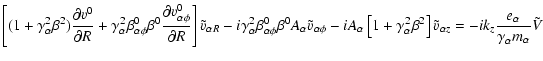
Equations (A.1)-(A.5) result in one equation for
![]() :
:
 |
(A.7) | ||
| (A.8) | |||
| (A.9) | |||
| (A.10) | |||
 |
(A.11) | ||
 |
(A.12) |
![\begin{figure}
\par\includegraphics[width=7.5cm,clip]{3040f3.eps}\end{figure}](/articles/aa/full/2006/03/aa3040-05/img61.gif)
![\begin{figure}
\mbox{
\includegraphics[width=4.3cm]{3040f4a.eps}\hskip0.3cm
\inc...
...040f4d.eps}\hskip0.3cm
\includegraphics[width=4.3cm]{3040f4e.eps} }
\end{figure}](/articles/aa/full/2006/03/aa3040-05/img68.gif)
![\begin{displaymath}\omega_{\alpha}^2(R) + \epsilon_\alpha\omega_{\alpha}(R) \Ome...
...alpha}R}\left[ E_R^0 - v_{\alphaz}^{0}(R)
B_\phi^S\right] = 0
\end{displaymath}](/articles/aa/full/2006/03/aa3040-05/img121.gif)
![$\displaystyle \tilde{\omega}_\alpha(R) = h \left\{\begin{array}{ll} 0 & \mbox{r...
...[2.5mm]
(1 - Q)\frac{R_2^2 - R_1^2}{R^2}& \mbox{region III}.
\end{array}\right.$](/articles/aa/full/2006/03/aa3040-05/img128.gif)
![\begin{displaymath}\psi^1(t, R, \phi, z) = \sum_{l = -\infty}^\infty \sum_{k_z =...
...y \tilde{\psi}(R) \exp[-{\rm i}(\omega t - l \phi - k_z
z)].
\end{displaymath}](/articles/aa/full/2006/03/aa3040-05/img140.gif)
![$\displaystyle \frac{1}{R}\frac{\partial }{\partial R}\left[R\left( 1 -
\sum_{\a...
...R} +
\frac{\partial v_{\alphaz}^{0}}{\partial R}\right)
\right)\right]\tilde{V}$](/articles/aa/full/2006/03/aa3040-05/img257.gif)
![$\displaystyle - k_z^2\left[ 1 - \sum_{\alpha}\frac{\omega_{p\alpha}^2}{A_\alpha...
...rtial \gamma_{\alpha}^{}}{\partial R}}{\nu_{\alpha}^2}\right) \right]\tilde{V}=$](/articles/aa/full/2006/03/aa3040-05/img258.gif)
![$\displaystyle \times \left[\beta_{\alpha\phi}^{}\beta_{\alphaz}^{}\left(2 A_\al...
...A_1 + 2 \omega_{\alpha}\beta_{\alpha\phi}^{02}\gamma_{\alpha}^{2}\right)\right]$](/articles/aa/full/2006/03/aa3040-05/img260.gif)
![$\displaystyle \frac{1}{R}\frac{\partial }{\partial R}\left[R\frac{\partial \tilde{V}}{\partial R}\right]
- \frac{l^2}{R^2}\tilde{V}$](/articles/aa/full/2006/03/aa3040-05/img267.gif)