 |
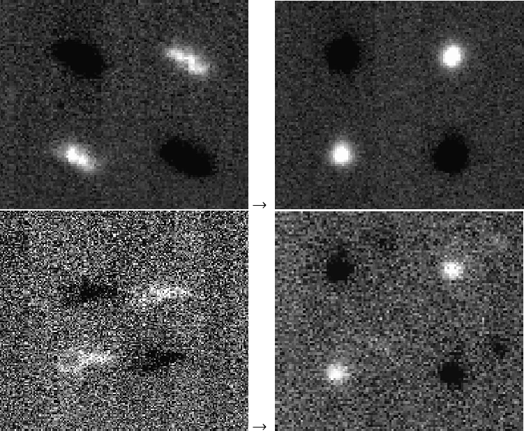
Figure 1: Pipeline-processing in comparison with re-reduced asteroid images. Top: Itokawa measurement #12 (Table 1), N1-filter, 7.5 min integration time, left: pipeline-product, right: the 60 raw images were shifted by 1.0 pixels per minute in x-direction and by -1.0 pixels per minute in y-direction and then co-added. Bottom: Itokawa measurement #20 (Table 1), Q1-filter, 25.8 min integration time, left: pipeline-product, right: the 234 raw images were shifted by 0.8 pixels per minute in x-direction and by 0.2 pixels per minute in y-direction and then co-added. |
| Open with DEXTER | |
In the text
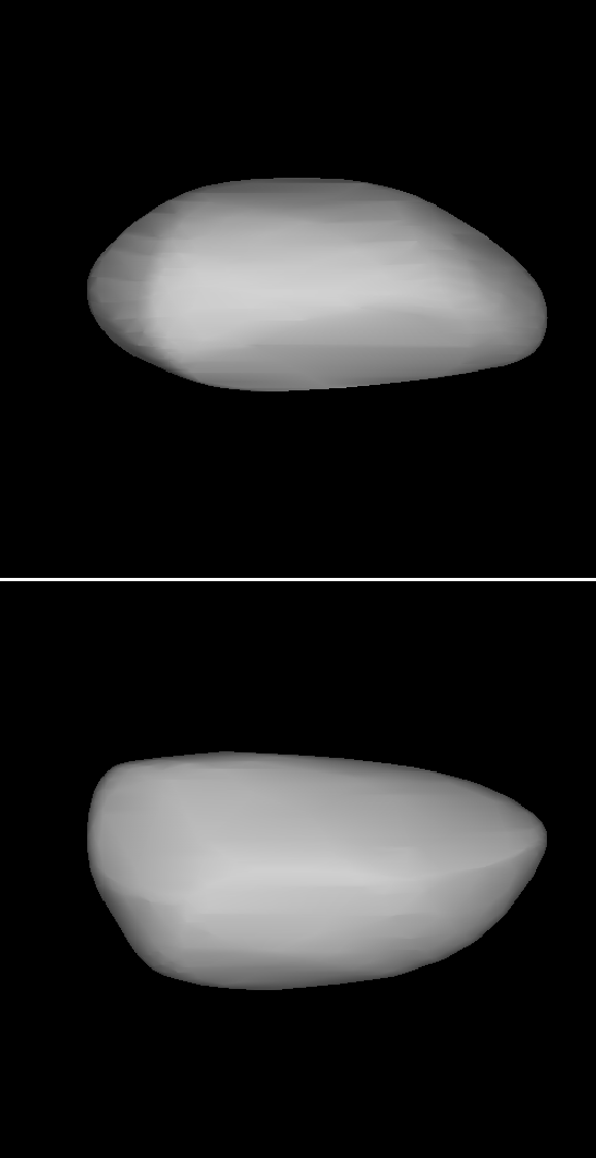 |
Figure 2: Equatorial edge-on ( top) and pole-on ( bottom) images of the shape model. |
| Open with DEXTER | |
In the text
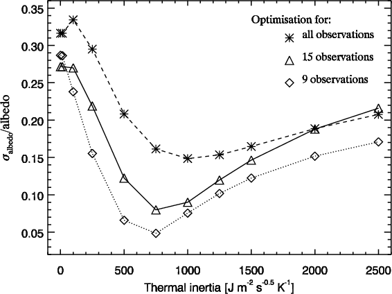 |
Figure 3: Thermal inertia optimisation process for the individual TPM albedos and their standard deviation, using all 20 individual observations (dashed line), a subset with 15 observations (solid line) and a subset of 9 observations (dotted line). |
| Open with DEXTER | |
In the text
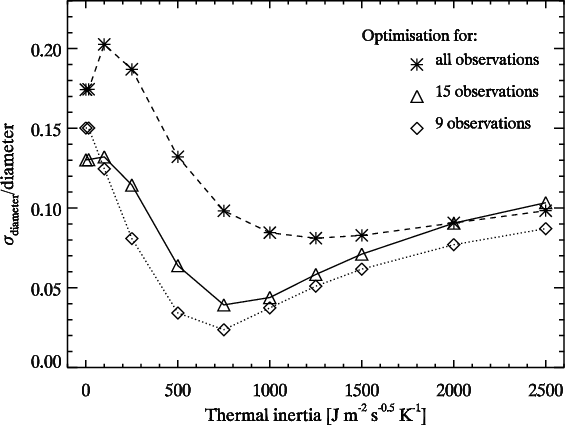 |
Figure 4: Thermal inertia optimisation process for the individual TPM diameters and their standard deviation, using all 20 individual observations (dashed line), a subset with 15 observations (solid line) and a subset of 9 observations (dotted line). |
| Open with DEXTER | |
In the text
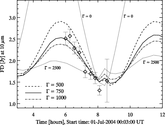 |
Figure 5:
Predicted thermal lightcurve at 10.0 |
| Open with DEXTER | |
In the text
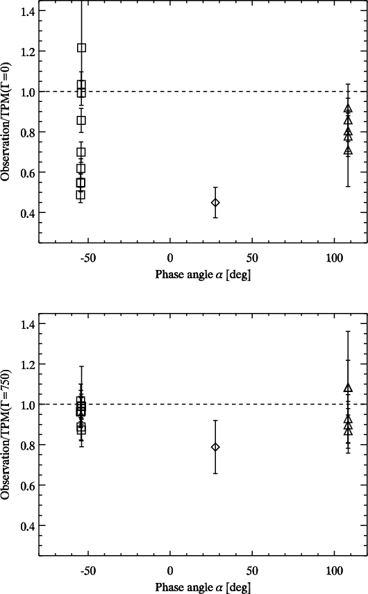 |
Figure 6: The observation/TPM ratios for a thermal inertia of 0 ( top) and 750 ( bottom). The high thermal inertia values eliminate the trend with phase angle and reduce the scatter significantly. |
| Open with DEXTER | |
In the text
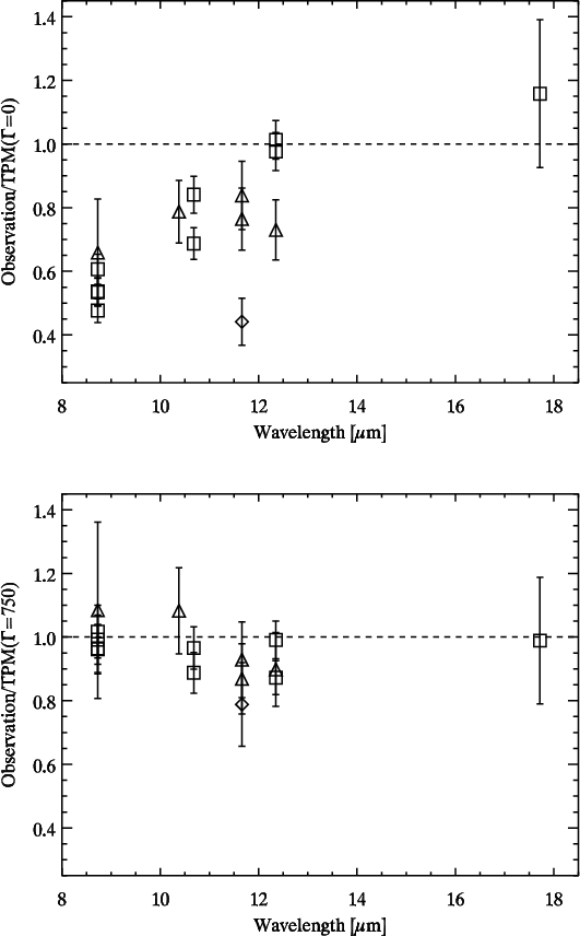 |
Figure 7: The observation/TPM ratios for a thermal inertia of 0 ( top) and 750 ( bottom). The high thermal inertia values eliminate the trend with wavelength and reduce the scatter significantly. |
| Open with DEXTER | |
In the text