A&A 439, 153-158 (2005)
DOI: 10.1051/0004-6361:20052951
D. Stamatellos - A. P. Whitworth
School of Physics & Astronomy, Cardiff University, 5 The Parade, Cardiff CF24 3YB, Wales, UK
Received 28 February 2005 / Accepted 25 April 2005
Abstract
We combine a Monte Carlo radiative transfer code with an SPH
code, so that - assuming thermal equilibrium - we can calculate
dust-temperature fields, spectral energy distributions, and isophotal maps,
for the individual time-frames generated by an SPH simulation. On large
scales, the radiative transfer cells (RT cells) are borrowed from the tree
structure built by the SPH code, and are chosen so that their size - and
hence the resolution of the calculated temperature field - is comparable
with the resolution of the density field. We refer collectively to these
cubic RT cells as the global grid. The code is tested and found
to treat externally illuminated dust configurations very well. However, when
there are embedded discrete sources, i.e. stars, these produce very steep
local temperature gradients which can only be modelled properly if -
in the immediate vicinity of, and centred on, each embedded star - we
supplement the global grid with a star grid of closely spaced
concentric RT cells.
Key words: ISM: clouds - ISM: structure - ISM: dust, extinction - methods: numerical - radiative transfer - hydrodynamics
Smoothed Particle Hydrodynamics (SPH) (Lucy 1977; Gingold & Monaghan 1977) is a Lagrangian computational method which invokes a large array of particles to describe a fluid, assigns properties such as mass, position and velocity to each particle, and estimates intensive thermodynamic variables like density and pressure (and their derivatives) using local averages (for reviews see Benz 1990, 1991; Monaghan 1992). The main advantage of this method is that, in principle, there are no limitations on the geometry of the system or how far it can evolve from the initial conditions.
Because of the large computational cost incurred when radiative transfer is modelled fully in three dimensions, many previous treatments have been limited to one or two dimensions (e.g. Efstathiou & Rowan-Robinson 1990, 1991; Men'shchikov & Henning 1997; Zucconi et al. 2001), and radiative transfer has only recently been included in SPH simulations, where a fully three-dimensional treatment is essential (Kessel-Deynet & Burkert 2000; Oxley & Woolfson 2003; Whitehouse & Bate 2004; Viau et al. 2005). The Monte Carlo approach for equilibrium radiative transfer (Lefevre et al. 1982, 1983; Wolf et al. 1999) is well suited to systems with arbitrary geometries, but, as with any Monte Carlo method, it is computationally expensive, especially when iteration is required. Recently, Bjorkman & Wood (2001), extended an idea by Lucy (1999) and proposed a method to avoid iteration, by remitting photons as soon as they are absorbed, with a frequency distribution adjustment technique. This method avoids iteration, and it is fast when compared with the traditional Monte Carlo radiative transfer methods. It has been applied successfully to a variety of problems, such as protoplanetary discs (e.g. Wood et al. 2002), prestellar cores (e.g. Stamatellos et al. 2004) and Class I objects (e.g. Whitney et al. 2003).
In this paper, we develop and test a method which uses Monte Carlo radiative transfer with frequency distribution adjustment, to calculate the dust-temperature field, the spectral energy distribution (SED), and isophotal maps, for individual time-frames from SPH simulations. We use the SPH tree to construct a grid of cubic radiative transfer cells (hereafter RT cells) with which the photons interact; we refer to this grid as the global grid. The global grid obtained in this way is similar to the tree-structured adaptive grid invoked by Kurosawa & Hillier (2001), but because it borrows the tree structure already derived as part of the SPH code, it minimizes the computational burden that will be added to the hydrodynamic simulations when the two methods are combined. A similar method has been used by Oxley & Woolfson (2003), but they adopt an average, wavelength-independent opacity. To account for the large temperature gradients that are expected very close to stars, we supplement the global grid described above with a grid of concentric spherical radiative transfer cells around each star; we refer to this supplementary grid as the star grid.
The Monte Carlo radiative transfer method (e.g. Stamatellos &
Whitworth 2003) uses a large number of monochromatic luminosity
packets (L-packets) to represent the radiation injected into
the medium (e.g. stellar radiation, cooling radiation, background
radiation). Each L-packet is given a random frequency, ![]() ,
and a
random optical depth,
,
and a
random optical depth, ![]() ,
which determines its free path, i.e. how far it travels before
interacting with the medium. The medium itself is
divided into a number of RT cells, each with uniform density and
temperature. Each time an L-packet is scattered, it is given a
new random direction, using the Henyey & Greenstein (1941)
scattering phase function, and a new random optical depth,
,
which determines its free path, i.e. how far it travels before
interacting with the medium. The medium itself is
divided into a number of RT cells, each with uniform density and
temperature. Each time an L-packet is scattered, it is given a
new random direction, using the Henyey & Greenstein (1941)
scattering phase function, and a new random optical depth, ![]() .
Each time an L-packet is absorbed, it raises the temperature of
the RT cell in which it is absorbed from T to
.
Each time an L-packet is absorbed, it raises the temperature of
the RT cell in which it is absorbed from T to
![]() ,
and the
packet is immediately reemitted isotropically, so that the dust is
in radiative equilibrium. The temperature of the RT cell is computed
by equating the total absorbed luminosity to the total emitted
luminosity. The frequency of the reemitted L-packet is chosen
using a probability distribution function (PDF) constructed from
the difference between the emissivity of the cell before and after
absorption of the L-packet (Bjorkman & Wood 2001; Baes et al.
2005),
,
and the
packet is immediately reemitted isotropically, so that the dust is
in radiative equilibrium. The temperature of the RT cell is computed
by equating the total absorbed luminosity to the total emitted
luminosity. The frequency of the reemitted L-packet is chosen
using a probability distribution function (PDF) constructed from
the difference between the emissivity of the cell before and after
absorption of the L-packet (Bjorkman & Wood 2001; Baes et al.
2005),
The radiative transfer cells must be constructed
so that their linear size is less than, or on the order of, the local
directional temperature- and density- scale-heights (e.g.
![]() ,
see Stamatellos & Whitworth 2003). This ensures that the temperature and
density do not vary too greatly between adjacent RT cells. The
construction of the RT cells depends on the specific system under study,
and, in an hydrodynamic simulation, where the system changes from step
to step, the RT cells need to be reconstructed at every step.
Therefore, a robust and efficient algorithm for the construction of
RT cells is required.
,
see Stamatellos & Whitworth 2003). This ensures that the temperature and
density do not vary too greatly between adjacent RT cells. The
construction of the RT cells depends on the specific system under study,
and, in an hydrodynamic simulation, where the system changes from step
to step, the RT cells need to be reconstructed at every step.
Therefore, a robust and efficient algorithm for the construction of
RT cells is required.
To construct RT cells we take advantage of the fact that our SPH code calculates gravitational forces with the aid of a spatial tessellation tree (Barnes & Hut 1986; Hernquist & Katz 1989). The whole computational domain is contained within a cubic cell, the root cell, which is then divided into eight smaller cubic cells of equal size. If any of these cells contains more than one particle, it is subdivided into eight even smaller cells. This procedure continues recursively until the smallest cells each contain just one particle or no particles at all. The resulting ensemble of cells constitutes the SPH tree. In SPH, the tree is used so that distant particles do not contribute individually to the local gravitational field, but collectively through the cell in which they are contained; the tree is also used to find neighbouring particles so that smoothed values of thermodynamic variables and their derivatives can be evaluated.
The global grid then comprises the smallest set of RT cells
which (a) spans the entire computational domain (or at least that part
of it containing matter) and (b) contains fewer
than
![]() SPH particles. If
SPH particles. If
![]() is chosen to be
of the same order as
is chosen to be
of the same order as
![]() (the number of neighbour particles
used for smoothing purposes), then the RT cells are
necessarily similar in size to the resolution of the SPH simulation.
Specifically we choose
(the number of neighbour particles
used for smoothing purposes), then the RT cells are
necessarily similar in size to the resolution of the SPH simulation.
Specifically we choose
![]() to 3, so
that each RT cell has linear size
to 3, so
that each RT cell has linear size ![]() 2 h (where h is the SPH smoothing length) and contains
2 h (where h is the SPH smoothing length) and contains ![]()
![]() particles.
particles.
This method of constructing RT cells is similar to the method of Kurosawa & Hiller (2001) (see also Kurosawa et al. 2004), but it is implemented using the Barnes & Hut (1986) tree structure. Both methods produce RT cells with approximately equal mass. It is also similar to the method used by Oxley & Woolfson (2003), but they construct RT cells with size 1/3 to 2/3 of the SPH smoothing length. Our method has the advantage that we can readily compute the density in an RT cell from the number of particles in the cell and the cell size, whereas in the Oxley & Woolfson method the density must be computed by an SPH sum over the neighbouring particles, and this is computationally expensive.
The method we use to construct RT cells, is implemented relatively easily within SPH and exploits information about the tree already calculated for SPH purposes. Thus, it does not add much to the code running time. It also furnishes us with an efficient procedure for finding which RT cell an L-packet is in. This is critical for the efficiency of the code, because as an L-packet propagates through the computational domain, this search procedure is performed many times.
The propagation of L-packets through the computational domain
is performed in small steps, ![]() ,
which gradually decrease
the optical depth
,
which gradually decrease
the optical depth ![]() of the L-packet until
of the L-packet until ![]() ,
whereupon the L-packet reaches an interaction point.
This is the most computationally expensive part of the code,
particularly as there is no analytical expression for the density
- and hence the opacity - along the path of an L-packet. Instead,
the density is determined by identifying the RT cell through which
the L-packet is passing. After each step
,
whereupon the L-packet reaches an interaction point.
This is the most computationally expensive part of the code,
particularly as there is no analytical expression for the density
- and hence the opacity - along the path of an L-packet. Instead,
the density is determined by identifying the RT cell through which
the L-packet is passing. After each step ![]() ,
we use the
SPH tree to find which RT cell i the L-packet is now in. The
search starts from the root cell and proceeds to lower level cells,
until the required RT cell is reached. The search contributes a
significant fraction of the code running time, and therefore, it
is essential to choose the step
,
we use the
SPH tree to find which RT cell i the L-packet is now in. The
search starts from the root cell and proceeds to lower level cells,
until the required RT cell is reached. The search contributes a
significant fraction of the code running time, and therefore, it
is essential to choose the step ![]() appropriately. We use
appropriately. We use
 |
(2) |
Kurosawa & Hiller (2001) adopt a more detailed approach, in which they use the path of an L-packet to determine where it intercepts the boundaries of the RT cells through which it passes. Our method is simpler to implement, it propagates the L-packets efficiently (usually the propagation step is on the order of the local RT cell size), and it is accurate (due to the fact that neighbouring RT cells have similar densities).
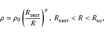
We consider a spherical cloud with uniform density
![]() ,
mass
,
mass
![]() and radius
and radius
![]() ,
and represent it with randomly distributed
SPH particles. We then test the method of constructing the global
grid and propagating L-packets through the grid in three ways. (i) We use the thermodynamic equilibrium test, where the cloud is bathed in
an isotropic blackbody radiation field with a given temperature
(Stamatellos & Whitworth 2003). (ii) We illuminate the cloud with the
Black (1994) interstellar radiation field (BISRF) and compare our results
with the results obtained previously using a spherically symmetric grid
of concentric cells (Stamatellos & Whitworth 2003). (iii) We embed a
low-temperature star at the centre of the cloud and again compare the
results with those obtained previously using a spherically symmetric
grid of concentric cells (see online appendix).
We present the results in the following subsections.
,
and represent it with randomly distributed
SPH particles. We then test the method of constructing the global
grid and propagating L-packets through the grid in three ways. (i) We use the thermodynamic equilibrium test, where the cloud is bathed in
an isotropic blackbody radiation field with a given temperature
(Stamatellos & Whitworth 2003). (ii) We illuminate the cloud with the
Black (1994) interstellar radiation field (BISRF) and compare our results
with the results obtained previously using a spherically symmetric grid
of concentric cells (Stamatellos & Whitworth 2003). (iii) We embed a
low-temperature star at the centre of the cloud and again compare the
results with those obtained previously using a spherically symmetric
grid of concentric cells (see online appendix).
We present the results in the following subsections.
We use
![]() SPH particles and set the maximum number
of particles in an RT cell to
SPH particles and set the maximum number
of particles in an RT cell to
![]() ,
giving
,
giving
![]() RT cells, each containing on average
RT cells, each containing on average
![]() SPH particles. The density in each RT cell is plotted as a function of
radius in Fig. 1a. Because the SPH particles are
distributed randomly, there are statistical variations in the density
at the
SPH particles. The density in each RT cell is plotted as a function of
radius in Fig. 1a. Because the SPH particles are
distributed randomly, there are statistical variations in the density
at the ![]()
![]()
![]() level. There are also
a number of RT cells that appear to be outside the boundary of the cloud
and to have very low density. In reality, only a small part of each of
these RT cells is within the cloud and therefore they contain only a very
small number of particles. These irregular RT cells are a side effect of representing a spherical cloud
with a grid of cubic cells. The same problem was also encountered by
Oxley & Woolfson (2001).
level. There are also
a number of RT cells that appear to be outside the boundary of the cloud
and to have very low density. In reality, only a small part of each of
these RT cells is within the cloud and therefore they contain only a very
small number of particles. These irregular RT cells are a side effect of representing a spherical cloud
with a grid of cubic cells. The same problem was also encountered by
Oxley & Woolfson (2001).
| |
Figure 1:
A uniform-density spherical cloud,
represented by 20 000 SPH particles, is illuminated by an isotropic
blackbody radiation field at
|
| Open with DEXTER | |
108 L-packets are then injected from random positions on the
boundary of the cloud, and with random frequencies and injection
angles, so as to imitate an isotropic blackbody radiation field at
![]() (see Stamatellos et al. 2004). The cloud should then
adopt the temperature of the illuminating radiation field, i.e.
(see Stamatellos et al. 2004). The cloud should then
adopt the temperature of the illuminating radiation field, i.e.
![]() .
The computed temperature of each RT cell is plotted
on Fig. 1b. In the body of the cloud the
temperature is very close to
.
The computed temperature of each RT cell is plotted
on Fig. 1b. In the body of the cloud the
temperature is very close to
![]() ,
with the error being less
than
,
with the error being less
than ![]()
![]() .
The errors are higher near and outside the boundary of
the cloud, because of the presence of the irregular RT cells. These
errors can be reduced by increasing the number of SPH particles,
and/or the number of RT cells, and/or the number of L-packets.
.
The errors are higher near and outside the boundary of
the cloud, because of the presence of the irregular RT cells. These
errors can be reduced by increasing the number of SPH particles,
and/or the number of RT cells, and/or the number of L-packets.
We use
![]() SPH particles and set the maximum
number of particles in an RT cell to
SPH particles and set the maximum
number of particles in an RT cell to
![]() ,
giving
,
giving
![]() RT cells, each containing on average
RT cells, each containing on average
![]() SPH particles. 108 L-packets are then injected from
random positions on the boundary of the cloud, and with random
frequencies and injection angles, so as to imitate the isotropic
Black (1994) interstellar radiation field (BISRF). The advantage of
this test is that the BISRF covers a wide wavelength range, including
regions where scattering dominates (UV
and optical) and regions where absorption/emission dominates (IR and submm). Therefore, we can test the validity of the method over
a wide range of wavelengths. Figure 2 compares
the resulting temperature profile and SED with accurate results
obtained using a spherically symmetric grid of thin concentric
RT cells. The agreement is very good, apart from the irregular RT cells
at the boundary.
SPH particles. 108 L-packets are then injected from
random positions on the boundary of the cloud, and with random
frequencies and injection angles, so as to imitate the isotropic
Black (1994) interstellar radiation field (BISRF). The advantage of
this test is that the BISRF covers a wide wavelength range, including
regions where scattering dominates (UV
and optical) and regions where absorption/emission dominates (IR and submm). Therefore, we can test the validity of the method over
a wide range of wavelengths. Figure 2 compares
the resulting temperature profile and SED with accurate results
obtained using a spherically symmetric grid of thin concentric
RT cells. The agreement is very good, apart from the irregular RT cells
at the boundary.
| |
Figure 2:
A uniform-density spherical cloud, represented by 200 000 SPH particles, is illuminated by the BISRF radiation field, using
108 L-packets. RT cells are constructed with
|
| Open with DEXTER | |
The presence of a normal- or high-temperature star in an SPH simulation makes the treatment of radiation transport more complicated, firstly because in the immediate vicinity of the star the dust is destroyed by sublimation and/or chemical sputtering (e.g. Lenzuni et al. 1995), and secondly because just outside this region there are very large temperature gradients which cannot be captured by the global grid.
The dust destruction temperature is
estimated to be between
![]() and
and
![]() (Lenzuni et al. 1995; Duschl et al. 1996) and depends on the assumed dust composition. The heating
rate for an isolated dust grain at distance R from a
star having radius
(Lenzuni et al. 1995; Duschl et al. 1996) and depends on the assumed dust composition. The heating
rate for an isolated dust grain at distance R from a
star having radius ![]() and surface temperature
and surface temperature ![]() is
is
 |
(5) |
 |
(6) |
![\begin{figure}
\par\includegraphics[width=8.8cm,clip]{2951fig5.ps}
\end{figure}](/articles/aa/full/2005/31/aa2951-05/img72.gif) |
Figure 3: a) The square cells represent the global grid derived from the SPH tree, and the concentric circles represent the additional star grid. b) The dashed horizontal lines show the temperature computed (inaccurately) using the global grid on its own, whilst the solid curve shows the (accurate) temperature profile computed using the additional star grid. |
| Open with DEXTER | |
The density and temperature gradients close to a star are large,
and can only be resolved with RT cells whose radial extent is comparable
with, or smaller than, the dust destruction radius
![]() .
Unless an impractically large number of SPH particles has been used
in the simulation, the cubic RT cells of the global grid (with size
.
Unless an impractically large number of SPH particles has been used
in the simulation, the cubic RT cells of the global grid (with size ![]() ,
where h is the smoothing length of the SPH kernel) are much larger
than
,
where h is the smoothing length of the SPH kernel) are much larger
than
![]() ,
as illustrated schematically in
Fig. 3. Thus the steep temperature gradients in
the vicinity of the star occupy only a few RT cells of the global grid,
and they are not properly resolved. Consequently the temperatures very
close to the star are underestimated. (Further out the temperature may be
overestimated or underestimated, but this is less critical.) The
upshot is that L-packets which are absorbed very close to the star
are then re-emitted from a wavelength distribution corresponding to
an inappropriately low temperature, and hence at inappropriately long
wavelengths. This means that they are able to propagate further away
from the star, or even to escape from the system altogether.
Consequently the SED has a deficit of radiation at the short (mainly
NIR) wavelengths emitted by hot dust, and a corresponding excess of
radiation at long (mainly FIR) wavelengths. This problem also arises
in the simulations of Kurosawa et al. (2004).
,
as illustrated schematically in
Fig. 3. Thus the steep temperature gradients in
the vicinity of the star occupy only a few RT cells of the global grid,
and they are not properly resolved. Consequently the temperatures very
close to the star are underestimated. (Further out the temperature may be
overestimated or underestimated, but this is less critical.) The
upshot is that L-packets which are absorbed very close to the star
are then re-emitted from a wavelength distribution corresponding to
an inappropriately low temperature, and hence at inappropriately long
wavelengths. This means that they are able to propagate further away
from the star, or even to escape from the system altogether.
Consequently the SED has a deficit of radiation at the short (mainly
NIR) wavelengths emitted by hot dust, and a corresponding excess of
radiation at long (mainly FIR) wavelengths. This problem also arises
in the simulations of Kurosawa et al. (2004).
To resolve this problem, we construct an extra grid of concentric shells (a star grid) around each star (see Fig. 3). To construct a star grid, we must specify:
However, we note that a spherically symmetric star grid may not be appropriate when the dust close to a star is concentrated in a disc. This situation can be handled with a simple extension to the method we have presented here, and it will be discussed in the companion paper (Stamatellos et al. 2005).
We represent the envelope using 20 000 SPH particles, distributed
randomly so that they approximate to an R-2 profile. (The approximation could be improved by settling
the distribution to get rid of Poisson fluctuations, but we have not
done this.) We use the SPH tree to construct a global grid with
![]() (which gives
(which gives
![]() and
and
![]() ). In addition, we have the option to introduce a star grid
comprising 30 concentric RT cells, between
). In addition, we have the option to introduce a star grid
comprising 30 concentric RT cells, between
![]() and
and
![]() .
.
The results are compared with the very accurate results obtained using a one-dimensional spherically symmetric code in Stamatellos & Whitworth (2003), hereafter "the benchmark calculation''.
We have performed the Ivezic test with
![]() and p = -2, using
and p = -2, using
![]() L-packets, both without
(Fig. 4), and with (Fig. 5), a
star grid around the central star.
L-packets, both without
(Fig. 4), and with (Fig. 5), a
star grid around the central star.
Without a star grid around the central star
(Fig. 4) the cubic RT cells of the global grid
in the vicinity of the star have size ![]()
![]() ,
and
therefore they are unable to capture the large temperatures and densities
there. This has two effects. First, the hottest dust is only
at
,
and
therefore they are unable to capture the large temperatures and densities
there. This has two effects. First, the hottest dust is only
at ![]()
![]() (rather than
(rather than ![]()
![]() in the benchmark
calculation), and consequently the SED shows a deficit of radiation at
wavelengths around
in the benchmark
calculation), and consequently the SED shows a deficit of radiation at
wavelengths around
![]() .
Second, the uniform density in the
individual RT cells reduces the net radial optical depth,
allowing more radiation to escape directly from the central star
(specifically
.
Second, the uniform density in the
individual RT cells reduces the net radial optical depth,
allowing more radiation to escape directly from the central star
(specifically
![]() ); this shows up in
the SED as an excess of radiation at wavelengths around
); this shows up in
the SED as an excess of radiation at wavelengths around
![]() .
.
With a star grid around the central star
(Fig. 5), the innermost RT cell (immediately outside
![]() )
has radial extent
)
has radial extent ![]()
![]() ,
and the high temperatures and densities near the star are
properly represented. Agreement with the benchmark calculation is then
very good. Small differences are due to statistical noise in RT cells which
do not intercept many L-packets.
,
and the high temperatures and densities near the star are
properly represented. Agreement with the benchmark calculation is then
very good. Small differences are due to statistical noise in RT cells which
do not intercept many L-packets.
| |
Figure 4:
Ivezic test with
|
| Open with DEXTER | |
| |
Figure 5:
Same as Fig. 4 but with an additional
star grid around the star, i.e. a volume devoid
of matter inside
|
| Open with DEXTER | |
In this paper we have presented a method for performing radiative transfer calculations on individual time-frames from SPH simulations. We use the SPH tree to construct a global grid of radiative transfer (RT) cells. This grid is constructed so that each RT cell contains a number of SPH particles close to the number of neighbours that each particle must have in SPH for smoothing purposes. The method thereby creates RT cells with size on the order of the local SPH smoothing length.
We test the method using the thermodynamic equilibrium test for a uniform-density spherical cloud, bathed in a blackbody radiation field. The method performs this test well. The global grid of RT cells that represent the cloud acquire the same temperature as the blackbody radiation field. The temperature is slightly underestimated near the boundary of the cloud due to the presence of RT cells that contain only a few SPH particles (irregular RT cells). The method also performs well for a uniform-density cloud illuminated by the interstellar radiation field.
We then examine a system comprising a low-temperature star embedded at the centre of a uniform-density spherical cloud. The temperature field and the SED are calculated with good accuracy. Very close to the star the temperature is slightly underestimated due to the fact that the temperature field there is not properly resolved. This in turn distorts the SED of the system slightly at short wavelengths. The problem is more pronounced when a normal- or high-temperature star is embedded in the cloud. The region very close to the star is then characterised by a very steep temperature gradient which cannot normally be captured by the cubic RT cells of the global grid, because these RT cells are too large.
To solve this problem we introduce an additional grid of concentric spherical RT cells around the star (the star grid). The star grid accounts for the dust-free region near the star, and its concentric spherical RT cells are small enough to capture steep temperature gradients, so that temperatures are calculated correctly close to the star. We test the use of a global grid in tandem with a star grid around the star, using the configuration proposed by Ivezic et al. (1997), and show that it performs very well, even if the optical depth is very large.
Our radiative transfer code can therefore be applied to arbitrary SPH density fields to produce dust temperature distributions, SEDs and isophotal maps at different wavelengths. These can then be used to compare the results of hydrodynamic simulations with observations. In the companion paper (Stamatellos et al. 2005) we apply this method to the collapse of turbulent molecular cores and the early stages of star formation.
Acknowledgements
We gratefully acknowledge support from the EC Research Training Network "The Formation and Evolution of Young Stellar Clusters'' (HPRN-CT-2000-00155) and from PPARC (PPA/G/O/2002/00497). We would also like to thank J. Barnes for using his tree code (available online at http://www.ifa.hawaii.edu/~barnes/software.html).
We use
![]() SPH particles and set the maximum
number of particles in an RT cell to
SPH particles and set the maximum
number of particles in an RT cell to
![]() ,
giving
,
giving
![]() cells, each containing on average
cells, each containing on average
![]() SPH particles. 108 L-packets are emitted by a central
low-temperature "star'' having luminosity
SPH particles. 108 L-packets are emitted by a central
low-temperature "star'' having luminosity
![]() and
surface temperature
and
surface temperature
![]() .
Figure A.1 compares the resulting
temperature profile and SED with accurate results obtained using a
spherically symmetric grid of thin concentric RT cells. The global
grid used here has difficulty capturing the steep temperature
gradient near the star. As a result the temperatures near the
star are underestimated and the SED shows a deficit at
short wavelengths. The temperature is also not very accurate near the
boundary, due to the irregular RT cells there; and there are some small
uncertainties in the SED at wavelengths longer than
.
Figure A.1 compares the resulting
temperature profile and SED with accurate results obtained using a
spherically symmetric grid of thin concentric RT cells. The global
grid used here has difficulty capturing the steep temperature
gradient near the star. As a result the temperatures near the
star are underestimated and the SED shows a deficit at
short wavelengths. The temperature is also not very accurate near the
boundary, due to the irregular RT cells there; and there are some small
uncertainties in the SED at wavelengths longer than
![]() ,
due to the small number of L-packets generated at these wavelengths.
Otherwise the agreement is good.
,
due to the small number of L-packets generated at these wavelengths.
Otherwise the agreement is good.
We have performed the Ivezic test with
![]() and p = -2, using 107 L-packets, both without
(Fig. A.2), and with (Fig. A.3),
a star grid around the central star.
and p = -2, using 107 L-packets, both without
(Fig. A.2), and with (Fig. A.3),
a star grid around the central star.
Without a star grid around the central star (Fig. A.2),
the cubic RT cells of the global grid in the
vicinity of the star are again unable to capture the large temperatures
and densities there. Consequently the hottest dust is only at ![]()
![]() (rather than
(rather than ![]()
![]() in the benchmark
calculation). The SED is dominated by the emission from this
dust, which peaks around
in the benchmark
calculation). The SED is dominated by the emission from this
dust, which peaks around
![]() .
In addition, the uniform
densities in the RT cells reduces the effective
radial optical depth (
.
In addition, the uniform
densities in the RT cells reduces the effective
radial optical depth (
![]() )
and
so there is a small shoulder at
)
and
so there is a small shoulder at ![]()
![]() ,
due to radiation
which escapes directly from the central star.
,
due to radiation
which escapes directly from the central star.
With a star grid around the central star (Fig. A.3) agreement with the benchmark calculation is very good. Small differences are again due to statistical noise. We emphasize that these calculations were performed with only 107 L-packets.
| |
Figure A.3:
Same as Fig. A.2 but with an additional
star grid around the star, i.e. a volume devoid
of matter inside
|