A&A 436, 1159-1165 (2005)
DOI: 10.1051/0004-6361:20042512
G. de Gasperis1 - A. Balbi1,2 - P. Cabella1 - P. Natoli1,2 - N. Vittorio1,2
1 - Dipartimento di Fisica, Università di Roma "Tor
Vergata'', via della Ricerca Scientifica 1, 00133, Roma, Italy
2 -
Sezione INFN Roma 2, via della Ricerca Scientifica 1, 00133,
Roma, Italy
Received 9 December 2004 / Accepted 3 February 2005
Abstract
We present ROMA, a parallel code to produce joint optimal
temperature and polarisation maps out of multidetector CMB
observations. ROMA is a fast, accurate, and robust implementation of
the iterative generalised least-squares approach to map-making. We
benchmark ROMA on realistic simulated data from the last
polarisation-sensitive flight of BOOMERanG.
Key words: cosmology: cosmic microwave background - methods: statistical - methods: data analysis
A direct consequence of the presence of anisotropies in the Cosmic Microwave Background (CMB) radiation is a certain degree of polarisation (Rees 1968; Kaiser 1983). Constraining CMB polarisation provides valuable cosmological information complementary to that encoded in temperature anisotropy, and it significantly tightens the constraints on cosmological parameters (Seljak & Zaldarriaga 1996).
Unfortunately, the polarised component of the CMB is expected to be
small compared to total intensity, making its measurement an
experimental challenge. For this reason and until very recently, the
experimental effort has not focused on the polarised component.
However, the situation is quickly changing. A first detection of CMB polarisation, in agreement with theoretical predictions, has been
announced by the interferometric experiment DASI
(Kovac et al. 2002). The WMAP satellite
(Bennett et al. 2003) has measured the predicted correlation
spectrum between CMB temperature anisotropy and polarisation
(Kogut et al. 2003). Many other CMB polarisation experiments
(DASI, CBI, CAPMAP, BICEP, QUEST, BOOMERanG 2K, MAXIPOL, SPORT,
BarSPORT, PLANCK, etc.![]() ) have either already taken
data or are expected to do so in the very near future.
) have either already taken
data or are expected to do so in the very near future.
It is well known that in CMB science the data reduction process requires almost as much care as data gathering. Analysis of temperature data has now reached full maturity and has proved successful on several datasets. The same is not true for polarisation. Although the overall analysis scheme can be borrowed from the temperature case, and many of the algorithms involved admit a more or less straightforward generalisation, polarised data sets present peculiar aspects that call for specific treatments. One basic problem is that the tensor-like nature of polarisation poses some constraints on the measurement process (see Cabella & Kamionkowski 2004; or Lin & Wandelt 2004, for recent reviews). As a consequence, not all possible instrumental configurations are equally advantageous from the point of view of data reduction (Couchot et al. 1999). The so called "optimal'' configurations comprise several different polarisation sensitive detectors (polarimeters) placed at a convenient reciprocal orientation. Usually data streams from different polarimeters are jointly analysed to seek a faint signal. The difficulties involved in this process and their relation to the design of robust and efficient data mining algorithms are seldom considered in the literature (see Revenu et al. 2000, for a notable exception).
Two major steps in the data analysis process are (1) production of sky maps from a set of Time Ordered Data (TOD) and (2) extraction of the angular power spectrum from such maps. Here we focus on the first step and will leave the discussion of the power spectrum estimation to a forthcoming paper. In a previous paper (Natoli et al. 2001) we described implementation of an optimal map-making algorithm for the case of temperature-only TOD collected by a one horned CMB experiment, and showed the feasibility of the method by applying it to PLANCK and BOOMERanG simulated data. Here we discuss the generalisation of this algorithm to the case of TOD produced by an arbitrary number of polarisation sensitive detectors. The software implementation of this method, which we call ROMA (Roma Optimal Map-making Algorithm), allows fast and efficient production of optimal multidetector maps of CMB total intensity and polarisation. The code is currently being used to analyse the polarised data set from the second Antarctic flight of the BOOMERanG experiment (hereafter B2K; Montroy et al. 2003), which took place in January 2003. ROMA is part of a full end-to-end data analysis pipeline for B2K, completely developed in Rome, and its details will be described elsewhere.
The plan of this paper is as follows. In Sect. 2 we derive the least-squares equations for multidetector map-making; then in Sect. 3 we describe the details of the implementation, while in Sect. 4 we report application of ROMA to highly realistic B2K simulated data. Finally, in Sect. 5, we draw our main conclusions.
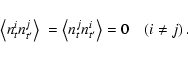
In this section we derive the Generalised Least Squares (GLS) equations for the polarised map-making problem, given an arbitrary number of polarimeters. With "polarimeter'' we mean, here and in the following, a generic detector measuring total intensity plus a linear polarisation component. Other types of detectors do exist and rely on different strategies to measure polarisation. We prefer to focus on the linear polarimeter case because of its widespread adoption. In any case it should be straightforward to generalise this scheme once the data model is properly modified.
The sky signal seen by a polarimeter can be expressed
as (Chandrasekhar 1960)
All three relevant Stokes parameters can be extracted by either
combining the output of many detectors with different mutual
orientation or by allowing enough focal plane rotation. The data
stream output of a given detector is a combination of sky signal and
instrumental correlated noise
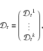
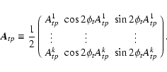
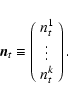
By inserting the trigonometric functions within the pointing matrix and considering a set of k polarimeters, one can recast Eq. (2) into a more compact formalism:

 |
(6) |
The treatment above is clearly idealistic; however, it is possible
for the formalism to
incorporate correction for a nominal level of
cross polarisation, one of the most common systematic effects
occurring in CMB polarimetry. Cross-polarisation occurs because of cross-talk
between the two orthogonal polarisation modes; that is, a polarimeter
may be sensitive, with efficiency
![]() ,
to radiation
linearly polarised
,
to radiation
linearly polarised
![]() off its natural polarisation mode. If we
assume that the cross-polarisation contamination is measurable (by
on-ground and/or in-flight tests) and is constant across the
mission lifetime, the formalism expressed above can be generalised to
take this effect into account. If we introduce a calibration constant C and a cross-polarisation factor
off its natural polarisation mode. If we
assume that the cross-polarisation contamination is measurable (by
on-ground and/or in-flight tests) and is constant across the
mission lifetime, the formalism expressed above can be generalised to
take this effect into account. If we introduce a calibration constant C and a cross-polarisation factor
![]() ,
the data
model Eq. (2) can be generalised as
,
the data
model Eq. (2) can be generalised as
![\begin{eqnarray*}\mathcal D_{t}^i &=& \frac{C}{2} A_{tp}^i \left[
\left( I_p +...
...s 2\phi_{t}^i -
U_p \sin 2\phi_{t}^i \right) \right] + n_{t}^i
\end{eqnarray*}](/articles/aa/full/2005/24/aa2512-04/img20.gif)
Straightforward implementation of Eq. (4) for a
modern CMB experiment would require storing and inverting a huge
matrix (the map noise correlation matrix), a task often beyond the
reach of today's supercomputers. In contrast, iterative
methods only require matrix to vector products and appear well suited
to tackling the problem. One such scheme proposed by Natoli et al.
(2001) has been shown to be particularly convenient in the case of
temperature map-making even for a high resolution full sky survey such
as PLANCK. The idea (Wright 1996) is to decompose the product
![]() ("unroll, convolve and
rebin'') to avoid computing and storing the map correlation matrix
and to make use of a preconditioned conjugate gradient (PCG) solver. The
key assumptions are: (1) assume that the beam is axisymmetric, so as to
keep the structure of the pointing matrix
("unroll, convolve and
rebin'') to avoid computing and storing the map correlation matrix
and to make use of a preconditioned conjugate gradient (PCG) solver. The
key assumptions are: (1) assume that the beam is axisymmetric, so as to
keep the structure of the pointing matrix ![]() as simple as
possible; and (2) assume that the noise is (piecewise, at least)
stationary and that its correlation function decays after a time lag
much shorter than the duration of the timeline piece being processed.
Under the last assumption, the
as simple as
possible; and (2) assume that the noise is (piecewise, at least)
stationary and that its correlation function decays after a time lag
much shorter than the duration of the timeline piece being processed.
Under the last assumption, the ![]() matrix is approximately
circulant, and as such it is diagonalized by a Fourier transform. This
approach achieves linear scaling (with the number of time samples) per
PCG iteration; if the system is preconditioned by the pixel hits
counter (the number of times each pixel is seen), an accurate solution
can be obtained in a few tens of iterations
(see Natoli et al. 2001, for a
discussion of algorithmic details; other implementations of this
approach include Doré et al. 2001; Cantalupo et al.;
and Jones et al. 2005).
matrix is approximately
circulant, and as such it is diagonalized by a Fourier transform. This
approach achieves linear scaling (with the number of time samples) per
PCG iteration; if the system is preconditioned by the pixel hits
counter (the number of times each pixel is seen), an accurate solution
can be obtained in a few tens of iterations
(see Natoli et al. 2001, for a
discussion of algorithmic details; other implementations of this
approach include Doré et al. 2001; Cantalupo et al.;
and Jones et al. 2005).
Our approach is to extend the above mentioned method to polarisation.
Since the timestream includes contributions from both total intensity
and linear polarisation (see Eq. (2)) it is desirable
to solve jointly for the temperature and polarisation maps in the
spirit of Eq. (4). This approach, which we call IQU,
is computationally more intensive than solving for I and (Q,U) separately, but preferable for at least two reasons: first, it
minimises the Q and U contaminations on the I map; second it is
more general, because it does not require any special constraint on
the noise properties of the polarisation sensitive detectors, as
would instead be the case when the TOD are explicitly differenced to
remove the intensity component. It is easy to realise that in the last
case the matrix ![]() would not be circulant except in the
special case of having identical noise properties in different
channels.
would not be circulant except in the
special case of having identical noise properties in different
channels.
While the intensity (temperature) field can theoretically be reconstructed from a single one-horned detector, up to the same order of magnitude as the polarisation contribution to the timeline, the same thing is not true for polarisation, unless special care is taken to ensure that the detector observes all pixels of the sky under very different orientations. The latter strategy has indeed been chosen by a few experiments (e.g. MAXIPOL that uses a rotating grid, Johnson et al. 2003), but the majority (e.g. B2K, PLANCK) plan to extract the polarisation maps by comparing channels with different mutual orientation of the plane sensitive to linear polarisation. If such a strategy is used, it is necessary to reduce several channels simultaneously in order to obtain a polarisation map; i.e. one is forced to perform multi-detector map-making. Of course, multi-detector map-making can also be performed in the case of polarisation insensitive detectors, when an optimal temperature map has to be produced out of different channels at a given frequency, not necessarily taken by the same experimental system. The IQU approach is thus very general, as it also allows us to merge naturally data taken by different channels, yet for temperature and polarisation at the same time.
Due to optical constraints, different detectors do not observe exactly
the same region of the sky during the mission lifetime, with the
notable exception of full sky surveys. A polarisation map can only
be extracted for pixels observed with sufficient variety in focal
plane orientation, in order not to incur an ill-conditioned
![]() matrix. Hence, it is a very
natural choice to restrict the polarisation map to intersection of the
sky regions surveyed by different detectors. We impose this
constraint by flagging the time samples associated to pixels outside
of the common region. A more refined discrimination would entail
explicitly selecting those pixels observed with enough spread in the
polarisation angle. For the sake of simplicity we choose to restrict
the (Q,U) maps to the intersection region of detector coverage. The
same constraint is neither necessary nor advantageous for the I map.
It is not necessary, because the temperature is normally well defined
outside of the commonly observed region, although in general with a
larger noise contribution; it is not advantageous, because of the way
the solver works. In fact, scans would often go continuously in and
out of the common region; when unrolling a tentative solution map
matrix. Hence, it is a very
natural choice to restrict the polarisation map to intersection of the
sky regions surveyed by different detectors. We impose this
constraint by flagging the time samples associated to pixels outside
of the common region. A more refined discrimination would entail
explicitly selecting those pixels observed with enough spread in the
polarisation angle. For the sake of simplicity we choose to restrict
the (Q,U) maps to the intersection region of detector coverage. The
same constraint is neither necessary nor advantageous for the I map.
It is not necessary, because the temperature is normally well defined
outside of the commonly observed region, although in general with a
larger noise contribution; it is not advantageous, because of the way
the solver works. In fact, scans would often go continuously in and
out of the common region; when unrolling a tentative solution map
![]() over the timestream (i.e. when performing the operation
over the timestream (i.e. when performing the operation
![]() ), the latter would display time gaps if the solution is
restricted to the common region. One way to tackle this problem is to
fill the gaps with a constrained noise realisation. This approach has
the disadvantage of increasing the computational cost of the
algorithm, because standard methods to produce constrained noise
realisations scale as the third power of the noise correlation length
(Hoffman & Ribak 1991). We instead prefer to avoid introducing
extra gaps in the unrolled timestream, to solve for I in the whole "union'' region, and to obtain a continuous
timestream using the I tentative solution map.
), the latter would display time gaps if the solution is
restricted to the common region. One way to tackle this problem is to
fill the gaps with a constrained noise realisation. This approach has
the disadvantage of increasing the computational cost of the
algorithm, because standard methods to produce constrained noise
realisations scale as the third power of the noise correlation length
(Hoffman & Ribak 1991). We instead prefer to avoid introducing
extra gaps in the unrolled timestream, to solve for I in the whole "union'' region, and to obtain a continuous
timestream using the I tentative solution map.
In the case of multi-detector, polarisation-sensitive map-making, it is a logical choice to use the global IQU maps as an estimate of the underlying signal. We will show below that this strategy achieves a substantial reduction in the estimated noise residual bias, by a factor depending on the number of detectors considered, as one would naively guess by applying a heuristic argument.
A significant fraction of the data gathered from a real world experiment are badly contaminated and cannot be used for science extraction. Corruption of these data normally occurs because of annoying events, either unpredictable (e.g. cosmic ray hits) or necessary (e.g. the ignition of a calibrator). Data loss can also affect pointing information; in this case for instance, the corresponding sky signal must be discarded even if usable per se. In any case, excerpting the affected samples destroys the timeline continuity and noise correlation. Both things must be reintroduced somehow, as is normally done by inserting a noise realisation, constrained to reproduce the correct statistical properties, while continuous (in a stochastic sense) at the gap boundaries (see Hoffman & Ribak 1991; Stompor et al. 2002). At the same time, the map making code must be warned that such samples do not contain any useful signal, a requirement trivially accomplished by associating a timeline "flag'' to all samples. Flagged samples do not project over the sky but are assigned to a virtual pixel whose value is estimated by the solver. Note that this scheme is equivalent to an ideally modified experiment that observes the sky and, for flagged samples, a null signal (virtual) pixel. The latter is eventually assigned a noise variance (and covariance to real pixels) compatible with instrumental properties. As shown in the next section, we find that this approach allows for precise signal recovery within the noise free limit, while correctly minimising the noise contribution in the weak signal regime.
To test ROMA we simulated and reduced a full mission scan (about 10 days) of the 145 GHz channels of the B2K experiment, using the nominal pointing solution, which includes a polarisation angle for each detector horn (de Bernardis, private communication).
B2K (Montroy et al. 2003) is basically the follow up of BOOMERanG
(Crill et al. 2003) featuring polarisation sensitive
bolometers (PSB) and a scanning strategy optimised to measure
polarisation of the CMB and of Galactic foregrounds. The portion of
the sky observed by B2K overlaps almost completely with the target of
the 1998 Antarctic campaign of BOOMERanG (de Bernardis et al. 2000).
However, the scanning strategy of B2K differs from the one implemented
for the previous flight. The survey area of B2K is split between a
![]() 300 square degrees region close to the Galactic plane and a low
foreground emission area of
300 square degrees region close to the Galactic plane and a low
foreground emission area of ![]() 1300 square degrees for CMB science. This area is in turn divided between a "shallow'' and a
"deep'' region which differ by more than an order of magnitude in
integration time per pixel. The deep region is totally embedded in the
shallow one and covers about 120 square degrees.
1300 square degrees for CMB science. This area is in turn divided between a "shallow'' and a
"deep'' region which differ by more than an order of magnitude in
integration time per pixel. The deep region is totally embedded in the
shallow one and covers about 120 square degrees.
In Fig. 1 we show the experimental setup of the B2K
focal plane, with the 145 GHz PSB's in the lower row.
![\begin{figure}
\par\includegraphics[angle=90,width=8.8cm,clip]{2512_f1.eps}
\end{figure}](/articles/aa/full/2005/24/aa2512-04/img31.gif) |
Figure 1: The B2K focal plane (Masi et al. 2003). The 145 GHz PSB's are located in the lower row. The upper detector row hosts unpolarised (spider web) bolometers coupled to a polarimeter. |
| Open with DEXTER | |
In simulating the data the following scheme is employed.
First we generate a
high resolution map (
![]() or
or
![]() in
HEALPix
in
HEALPix![]() language) of a standard CMB sky with
language) of a standard CMB sky with ![]() CDM cosmology, and then assume
a Gaussian beam of
CDM cosmology, and then assume
a Gaussian beam of
![]() FWHM for all the PSBs. The signal time
streams are then obtained using the nominal B2K scan. The noise time
streams are simulated by assuming the following form for the noise
spectral density
FWHM for all the PSBs. The signal time
streams are then obtained using the nominal B2K scan. The noise time
streams are simulated by assuming the following form for the noise
spectral density
As a first step we perform noise estimation. We follow the iterative scheme explained above and compare the quality of the noise spectrum recovered when using the single PSB (temperature only) maps as the signal baseline, as opposed to using the full (global) temperature map. Not surprisingly, in the latter case, the residual noise bias is substantially minimised, especially at intermediate frequencies (see Fig. 2) when compared to the by definition unbiased estimate of the power spectrum obtained from the noise-only TOD used in the S+N simulation.
![\begin{figure}
\par\includegraphics[width=8.8cm,clip]{2512_f2.eps}
\end{figure}](/articles/aa/full/2005/24/aa2512-04/img42.gif) |
Figure 2: The percentual ratio, as a function of frequency, between the noise power spectrum of a single detector estimated from the S+N data (by means of the iterative procedure described in the text) and the unbiased estimate of the same noise power spectrum obtained from the noise-only timestream. The black ( lower) curve is for a single detector case, while the blue ( upper) curve is obtained with a GLS map from all eight detectors. Note the strong suppression of residual bias in this case. |
| Open with DEXTER | |
The "signal plus noise'' (S+N) maps are displayed in
Fig. 4. We have accurately tested that the code
preserves linearity for the GLS solution it implements: that is,
running ROMA on a S+N timestream is equivalent to summing the output
of two separate S and N runs. Strictly speaking this statement
is true only if the code is allowed to iterate until the final
solution is reached. We found in practice that the linearity is very
well preserved after a reasonable number of iterations (![]() 100)
are completed.
100)
are completed.
![\begin{figure}
\par\includegraphics[angle=90,width=5.5cm]{2512_f3.ps}\hspace*{2m...
...}\hspace*{2mm}
\includegraphics[angle=90,width=5cm]{2512_f8.ps}
\end{figure}](/articles/aa/full/2005/24/aa2512-04/img43.gif) |
Figure 3:
Top row: I, Q, and U maps obtained by running ROMA on
eight "signal-only'' simulated timelines (one for each B2K
bolometer). The display area is restricted to the "shallow''
region. Bottom row: difference maps, computed by subtracting the
above maps from the simulated sky that was input to the
simulations. In doing so, the original maps have been degraded to
|
| Open with DEXTER | |
| |
Figure 4: From left to right, I, Q and U output ROMA maps on eight "signal plus noise'' simulated timelines. Assumptions for the noise properties are explained in the text. |
| Open with DEXTER | |
![\begin{figure}
\par\includegraphics[angle=90,width=7.5cm]{2512_f12.ps}\hspace*{2mm}
\includegraphics[angle=90,width=7.5cm]{2512_f13.ps}
\end{figure}](/articles/aa/full/2005/24/aa2512-04/img45.gif) |
Figure 5:
Left panel: difference between the input, simulated sky, and the
map output by ROMA, when processing a single-detector
"signal-only'' (i.e. noiseless) timeline. Both (input and
output) are intensity maps; the input map was degraded to
|
| Open with DEXTER | |
The importance of having a joint IQU solver is underlined by Fig. 5. Here we present, as for the bottom row of Fig. 3 above, the difference (input minus output) maps for a signal-only case. However (see also the figure's caption), here we show the residuals obtained when processing a single channel map, for which no polarisation solution can be found. As one would expect, this residual is dominated by a polarisation-like pattern, which the map-making code is unable to distinguish from the temperature signal.
Most of the computational effort required by ROMA is claimed by the
Fourier transforms needed to perform repeated convolutions with the
![]() matrix. An efficient FFT library must therefore be used.
Our choice fell on the publicly available FFTW3 library
(Frigo & Johnson 1998), which claims, in our case, about 80% of the total
computing time. Use of the FFT guarantees that the code scales
linearly (per PCG iteration) with the number of timeline samples, i.e.
with the dataset size. Strictly speaking, the FFT scales log-linearly
with time samples. However, when performing convolutions, we only take
the non-zero band of
matrix. An efficient FFT library must therefore be used.
Our choice fell on the publicly available FFTW3 library
(Frigo & Johnson 1998), which claims, in our case, about 80% of the total
computing time. Use of the FFT guarantees that the code scales
linearly (per PCG iteration) with the number of timeline samples, i.e.
with the dataset size. Strictly speaking, the FFT scales log-linearly
with time samples. However, when performing convolutions, we only take
the non-zero band of ![]() ,
a tunable but constant factor (see
Natoli et al. 2001). For the B2K test case under consideration, we find
that retaining a noise bandwidth of size
,
a tunable but constant factor (see
Natoli et al. 2001). For the B2K test case under consideration, we find
that retaining a noise bandwidth of size ![]() 105 is optimal and
that about 102 PCG iterations are needed to reach convergence
to better than 10-5 precision in the cases under consideration.
This can be achieved, for instance, in about 5 min on a 128 processor job of an IBM SP3, for the full (8 PSB,
105 is optimal and
that about 102 PCG iterations are needed to reach convergence
to better than 10-5 precision in the cases under consideration.
This can be achieved, for instance, in about 5 min on a 128 processor job of an IBM SP3, for the full (8 PSB,
![]() total samples) dataset (see also Fig. 6).
total samples) dataset (see also Fig. 6).
We have presented our state of the art map-making code developed to jointly reduce multichannel CMB anisotropy and polarisation data. ROMA is a parallel (MPI) implementation of the GLS approach to map-making, solved by a PCG iterative method. The only assumptions are that the optical beam is purely scalar and axisymmetric and that the timeline noise is (at least piecewise) stationary and uncorrelated across different detectors. For the rest, great care was taken in tackling real world issues, including cross-polarisation, multi-detector noise estimation, and the problem of missed data. As a test case we used ROMA to reduce eight PSB (145 GHz) timelines of highly realistic simulated B2K data. We show that the IQU maps can be recovered with great precision in the signal-only case, while attaining the usual GLS ("optimal'') noise suppression in the noisy case. To our knowledge, this is the first joint temperature and polarisation map-making code demonstrated to work on a realistic dataset. The code scales linearly with the dataset size, while its parallel behaviour is quasi-optimal, thus represents a viable option for reducing present and forthcoming large datasets, including PLANCK.
![\begin{figure}
\resizebox{8.8cm}{!}{\includegraphics[angle=0]{2512_f14.eps}} \end{figure}](/articles/aa/full/2005/24/aa2512-04/img47.gif) |
Figure 6:
Inverse time for a single PCG iteration as a function
of the number of processor elements (
|
| Open with DEXTER | |
Acknowledgements
This research used resources of the National Energy Research Scientific Computing Center, which is supported by the Office of Science of the US Department of Energy under Contract No. DE-AC03-76SF00098. We thank P. de Bernardis and the whole BOOMERanG collaboration for having provided us with the B2K scan and instrumental performances. We acknowledge use of the HEALPix package (Górski et al. 1999, 2004) and of the FFTW library (Frigo & Johnson 1998). We thank the CASPUR (Rome-ITALY) computational facilities for computing time and technical support. The authors wish to thank the PLANCK CTP working group and, in particular, C. M. Cantalupo and J. D. Borril for stimulating discussions.
![\begin{displaymath}\mathcal D_{t}^i = \frac{C_{\chi}}{2}
A_{tp}^i \left[I_p + ...
... 2\phi_{t}^i + U_p \sin 2\phi_{t}^i \right) \right] + n_{t}^i,
\end{displaymath}](/articles/aa/full/2005/24/aa2512-04/img21.gif)