 |
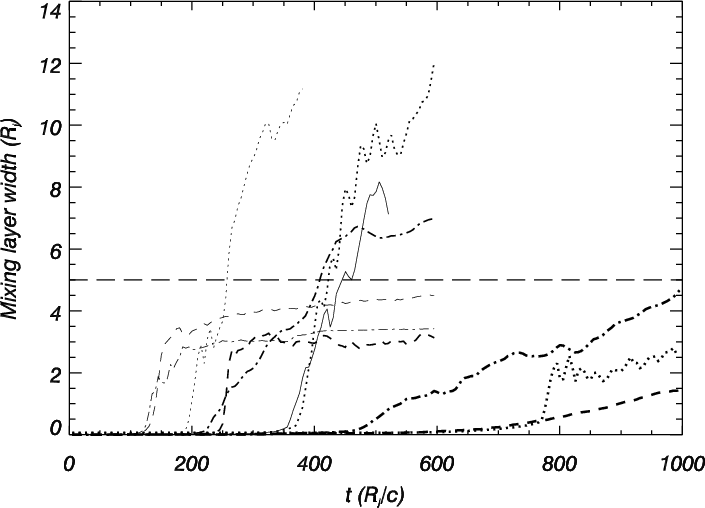
Figure 1:
Evolution of the mean width of the jet/ambient mixing layer
with time for all the simulations. Different types of lines are used
for models with different internal energies: Continuous line: model
A; dotted line: model B; dashed line: model C; dashed-dotted line:
model D. Line thickness increases with Lorentz factor (from 5,
thinest line, to 20 thickest one). A value of 5 |
| Open with DEXTER | |
In the text
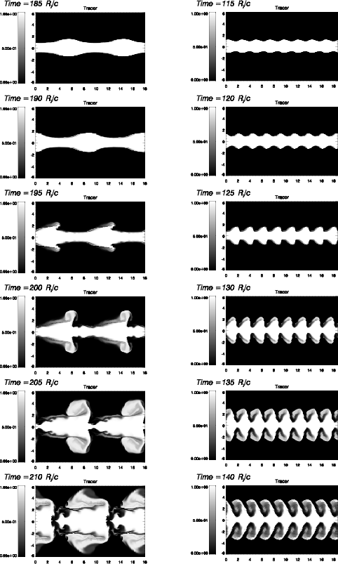 |
Figure 2: Evolution of the jet particle fraction showing the development of mixing in two representative models. Left column (model B05): the ambient material carves its way through the jet difficulting the advance of the jet material which is suddenly stopped. Right column (model D05): the amount of ambient matter hampering the jet material is smaller and matter from the jet at the top of the jet crests is ablated by the ambient wind. |
| Open with DEXTER | |
In the text
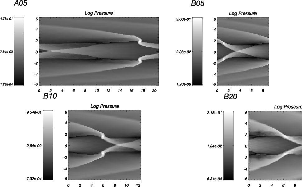 |
Figure 3:
Pressure distribution at the onset of the jet/ambient surface
distortion at the end of the saturation phase for models A05, B05,
B10 and B20. The corresponding times are 355, 190, 370 and 765
|
| Open with DEXTER | |
In the text
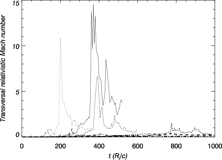 |
Figure 4:
Time evolution of the maxima of the transversal Mach number
of the jet with respect to the unperturbed ambient medium,
|
| Open with DEXTER | |
In the text
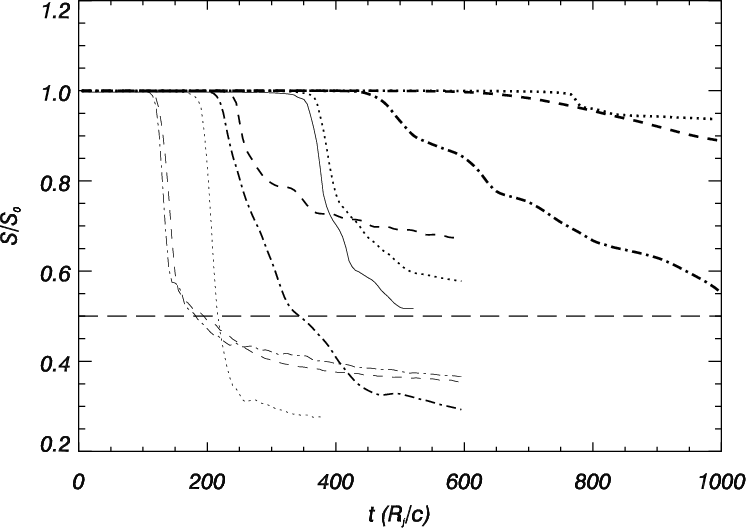 |
Figure 5: Evolution of the total longitudinal momentum in the jet as a function of time for all the simulations. Lines represent the same models than in Fig. 1. The long-dashed horizontal line serves us to identify those models tranferring more than 50% of the initial jet momentum to the ambient. |
| Open with DEXTER | |
In the text
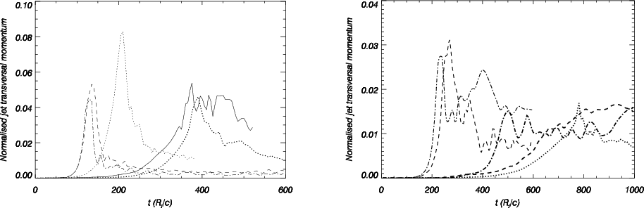 |
Figure 6: Evolution of the total transversal momentum in the jet as a function of time for all the simulations. Lines represent the same models than in Fig. 1. Left panel: models A05, B05, B10, C05, D05. Right panel: B20, C10, C20, D10, D20. Note the change in both horizontal and vertical scales between the two panels. |
| Open with DEXTER | |
In the text
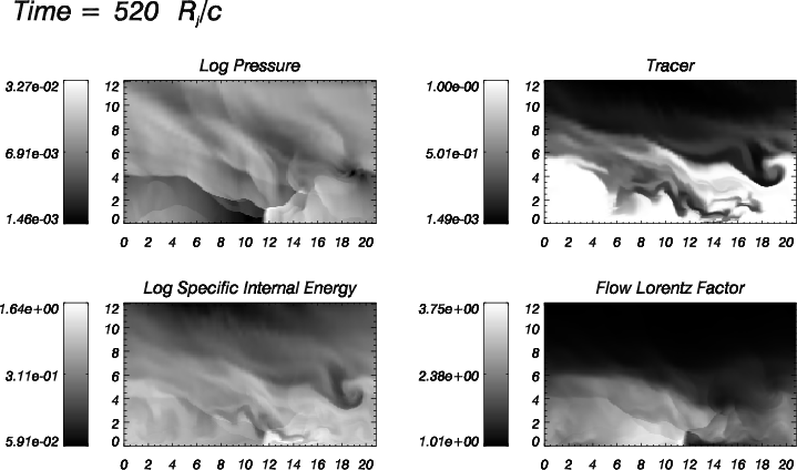 |
Figure 7: Snapshot in the mixing phase of logarithmic maps of pressure, jet mass fraction and specific internal energy and non-logarithmic Lorentz factor for model A05. Only the top half of the jet is shown. |
| Open with DEXTER | |
In the text
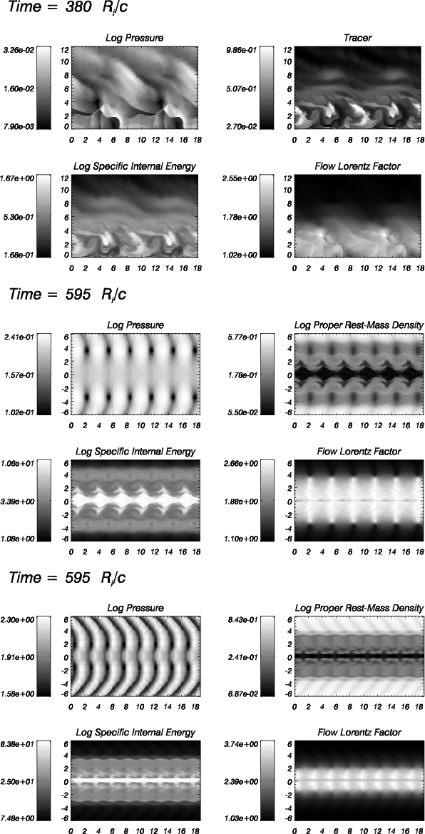 |
Figure 8: Same as Fig. 7 for models B05 ( upper; only top half of the model shown), C05 ( middle) and D05 ( lower). |
| Open with DEXTER | |
In the text
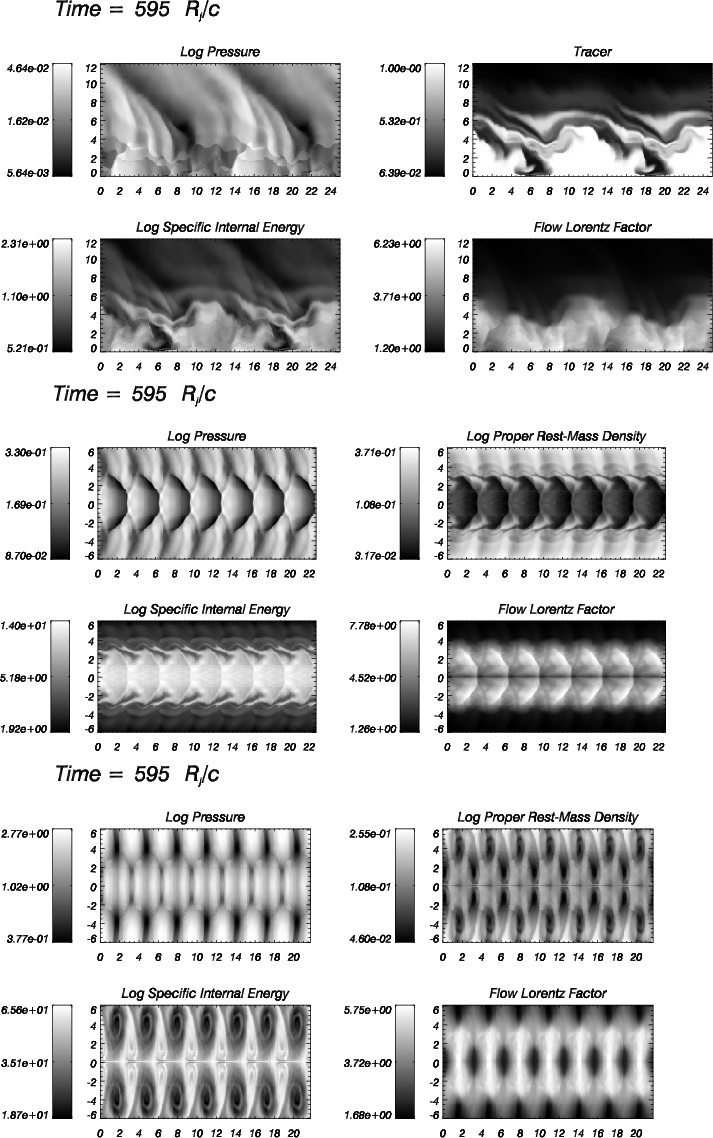 |
Figure 9: Same as Fig. 7 for models B10 ( upper; only top half of the model shown), C10 ( middle) and D10 ( lower; only top half of the model shown). |
| Open with DEXTER | |
In the text
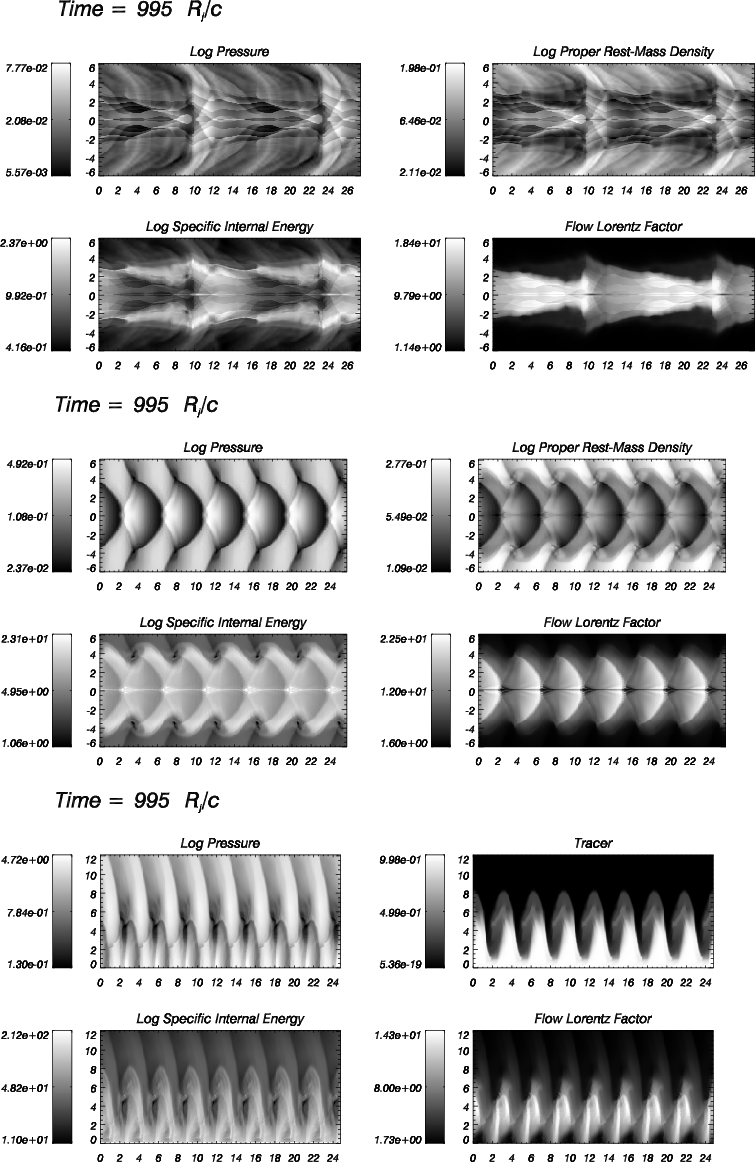 |
Figure 10: Same as Fig. 7 for models B20 ( upper), C20 ( middle) and D20 ( lower; only top half of the model shown). |
| Open with DEXTER | |
In the text
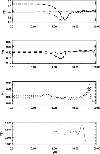 |
Figure 11: Longitudinal averaged profiles of gas pressure for all models. Different types of lines are used for models with different internal energies: Continuous line: model A; dotted line: model B; dashed line: model C; dashed-dotted line: model D. Line thickness increases with Lorentz factor (from 5, thinest line, to 20 thickest one). |
| Open with DEXTER | |
In the text
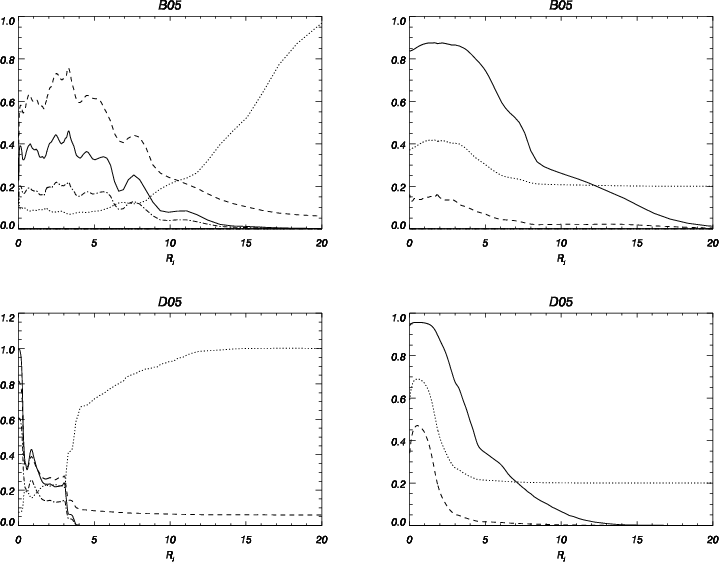 |
Figure 12:
Transversal averaged profiles of relevant physical quantities
at the end of simulations B05 and D05. Left column: tracer, f (full
line), rest mass density, |
| Open with DEXTER | |
In the text
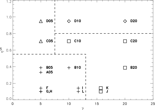 |
Figure 13: Square root of the jet-to-ambient enthalpy ratio (see Paper I for definitions) versus jet Lorentz factor. Symbols represent different non-linear behaviors: crosses stand for shock disrupted jets (cold, slow jets, along with tenuous, hot, moderately fast or slow ones); diamonds for unstable, hot, fast jets; triangles for relatively stable hot, slow, and squares for stable, warm, fast, along with hot, tenuous, faster jets. |
| Open with DEXTER | |
In the text
| |
Figure A.1: Same plots as 1 ( left) and 5 ( right) for models C16 (solid line), C32 (dotted line), C64 (dashed line) and C128 (dash-dotted line). |
In the text
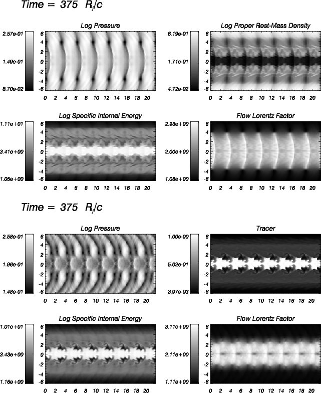 |
Figure A.2:
Snapshots at
|
In the text
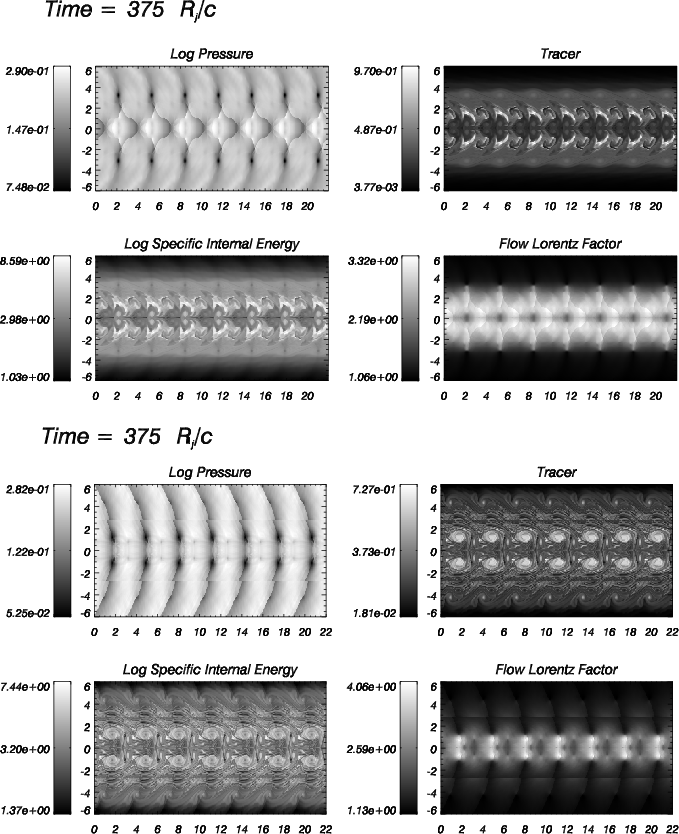 |
Figure A.3: Same as Fig. A.2 for models C64 ( upper) and C128 ( lower). |
In the text
In the text