A&A 426, 1093-1101 (2004)
DOI: 10.1051/0004-6361:20041367
P. C. Grigis - A. O. Benz
Institute for Astronomy, ETH Zürich, 8092 Zürich, Switzerland
Received 28 May 2004 / Accepted 15 July 2004
Abstract
The time evolution of the spectral index and the non-thermal flux in 24
impulsive solar hard X-ray flares of GOES class M was studied in RHESSI
observations. The high spectral resolution allows for a clean separation
of thermal and non-thermal components in the 10-30 keV range, where most
of the non-thermal photons are emitted. Spectral index and flux can thus
be determined with much better accuracy than before.
The spectral soft-hard-soft behavior in rise-peak-decay phases is discovered
not only in the general flare development, but even more pronounced in
subpeaks.
An empirically found power-law dependence between the spectral index and the
normalization of the non-thermal flux holds during the rise and decay phases
of the emission peaks. It is still present in the combined set of all flares.
We find an asymmetry in this dependence between rise and decay phases of
the non-thermal emission.
There is no delay between flux peak and spectral index minimum.
The soft-hard-soft behavior appears to be an intrinsic signature
of the elementary electron acceleration process.
Key words: Sun: flares - Sun: X-rays, gamma rays - acceleration of particles
Non-thermal hard X-ray emission during impulsive solar flares is highly variable, often showing activity peaks and dips with durations ranging from seconds up to several minutes. This behavior can be observed in the largest X class flares as well as in smaller B and C class flares. It was early recognized (Parks & Winckler 1969; Kane & Anderson 1970) that the hardness of the photon spectrum can also change with time, and, furthermore, that there is a direct correlation between the hard X-ray flux and the spectral hardness. Since this implies that the flare spectrum starts soft, gets harder as the flux rises and softer again after the peak time, the term soft-hard-soft (SHS) was coined to describe this behavior. Later observations of major flares (Benz 1977; Brown & Loran 1985; Lin & Schwartz 1986; Fletcher & Hudson 2002; Hudson & Fárník 2002) confirmed the SHS pattern. However, flares were also observed that systematically hardened with time (Frost & Dennis 1971; Cliver et al. 1986; Kiplinger 1995), thus showing a soft-hard-harder (SHH) pattern. Current wisdom suggests that SHH flares represent gradual, long duration events. These are much less frequent than impulsive events.
The non-thermal photons usually follow a power-law distribution
in energy. The power-law index, ![]() ,
can be
directly related to the energy distribution of the electron flux impinging
on the target (assuming a model for the bremsstrahlung emission),
and implicitly to the acceleration process. The evolution of spectral
index and flux reflects a development in the accelerator. Thus, the relation
between index and flux is an observational constraint for acceleration
theories.
,
can be
directly related to the energy distribution of the electron flux impinging
on the target (assuming a model for the bremsstrahlung emission),
and implicitly to the acceleration process. The evolution of spectral
index and flux reflects a development in the accelerator. Thus, the relation
between index and flux is an observational constraint for acceleration
theories.
While it seems to be well established that impulsive flares have an SHS
spectral dynamic, much less is known about the quantitative relation,
if any, between the photon spectral index and
the non-thermal X-ray flux during the burst.
The Reuven Ramaty High-Energy Solar Spectroscopic Imager (RHESSI)
spacecraft (Lin et al. 2002), which observes hard
X-rays and ![]() -rays from the sun, is ideally suited to explore
this relation. Its key features of high spectral resolution (1 keV in the
X-ray range) and coverage of the low-energy range (down to 3 keV)
allow us to separate the thermal continuum from the non-thermal component
of the spectrum, to study also the 10-30 keV region where most of the
non-thermal photons are emitted, to identify and account for peculiar
spectral features (like breaks in the power-law etc.),
and to follow the evolution of the non-thermal part right from the
onset of the flare. Therefore, the spectral index and flux of RHESSI
non-thermal photons can be studied with much higher precision than
previously.
-rays from the sun, is ideally suited to explore
this relation. Its key features of high spectral resolution (1 keV in the
X-ray range) and coverage of the low-energy range (down to 3 keV)
allow us to separate the thermal continuum from the non-thermal component
of the spectrum, to study also the 10-30 keV region where most of the
non-thermal photons are emitted, to identify and account for peculiar
spectral features (like breaks in the power-law etc.),
and to follow the evolution of the non-thermal part right from the
onset of the flare. Therefore, the spectral index and flux of RHESSI
non-thermal photons can be studied with much higher precision than
previously.
This paper presents a large set of measurements of the non-thermal component from 24 different solar flares and investigates quantitatively the relation between the non-thermal flux and the spectral index. The flares were selected in such a way as to represent the class of impulsive flares with strong non-thermal emission. In Sect. 2 we give a detailed description of the selection and data reduction process that yields the dataset which is then analyzed in Sect. 3 and discussed in Sect. 4.
Our main observational goal is the accurate study of the time evolution
of the spectral index ![]() and the non-thermal X-ray flux in a
representative sample of solar flares, using data from RHESSI.
In this section we give a detailed account of the different steps that were
undertaken in the data analysis process, starting from the event selection.
and the non-thermal X-ray flux in a
representative sample of solar flares, using data from RHESSI.
In this section we give a detailed account of the different steps that were
undertaken in the data analysis process, starting from the event selection.
The event selection has to be very careful in order to pick a representative collection of flares. Ideally, one would analyze all the observed events or a randomly chosen subset thereof. In practice, however, instrumental issues reduce the freedom of choice, since not all the events are equally suitable for the different tasks of high precision spectral analysis. A detailed discussion about the RHESSI onboard detectors and their use for spectroscopy can be found in Smith et al. (2002). We limited our analysis to flares having a peak soft X-ray flux larger than GOES class M1 and smaller than X1. These have fairly large count rates, but are not too heavily affected by pulse pileup. 176 M-class flares were reported in the RHESSI flare list in the period from 13 February 2002 to 31 November 2002. From this collection we restricted our analysis to the 79 flares observed with a constant attenuator state of 1 (thin attenuator in) and no front-segment decimation. Therefore we do not need to deal with attenuator motions and decimation state changes during the flare, and we have the best conditions for spectroscopy of M-class flares.
From this selection of 79 flares we dropped the ones which had no emission above the background in the 25-50 keV band, as determined by visual inspection of the observing summary light curves. Since we expect the bulk of the thermal radiation from M-class flares to be emitted mostly below 25 keV, this condition introduces a bias toward flares with substantial non-thermal emission. This is not a severe restriction, since we want to study specifically the non-thermal emission, and it would be very hard to ascertain the properties of any weak non-thermal emission anyway. In order to have enough data for meaningful time series, we additionally required the peak in the 25-50 keV band being more than 3 minutes away from any interruption in the data, as caused by the spacecraft entering or leaving the shadow of the Earth, the South Atlantic Anomaly (SAA), etc. We also dropped the events in which charged particle precipitation significantly increased the background counts during the time of enhanced emission in the 25-50 keV band. These additional criteria dropped the number of events to 32.
For each event in the list, we determined:
To derive the spectral indices for the spectra, we use the forward fitting
method implemented by the SPEX code (Schwartz 1996;
Smith et al. 2002).
The procedure requires the user to choose a model photon spectrum, which is
multiplied with the instrument response matrix and then fitted to the
observed count spectrum.
The best-fit parameters are given as output. To obtain the time evolution
of the parameters, the fitting procedure is performed for each time bin
in the spectrogram of the time interval of interest.
We have chosen to use a photon spectral model featuring a power-law with
a low-energy turnover in addition to a thermal thick-target bremsstrahlung
emission.
The negative power-law index below the low-energy turnover was fixed at 1.5.
Hence there are 5 free parameters in the model: the temperature T of the
assumed isothermal emission and its emission measure
![]() ;
for the
non-thermal component the power-law index
;
for the
non-thermal component the power-law index ![]() ,
the normalization of the power-law
,
the normalization of the power-law
![]() at the
(fixed) normalization energy E0 and the low-energy turnover
at the
(fixed) normalization energy E0 and the low-energy turnover
![]() .
The non-thermal part of the spectrum is thus given by
.
The non-thermal part of the spectrum is thus given by
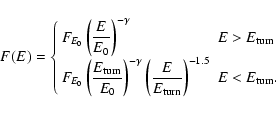 |
(1) |
![\begin{figure}
\par\includegraphics[width=8cm,clip]{1367fig1.eps}\end{figure}](/articles/aa/full/2004/42/aa1367/img24.gif) |
Figure 1:
A RHESSI photon spectrum for 9 November 2002 at 13:14:16 UT,
integrated over one rotation period of approximately 4 s.
Overlaid on it, an isothermal thick-target bremsstrahlung emission (dotted
line) with temperature
|
| Open with DEXTER | |
A time dependent determination of the model's best-fit parameters for
30 flares lasting a few minutes with 4 s data bins
requires more than thousand fittings.
To reduce the burden of the work involved in the data analysis,
we implemented an automatic fitting procedure. However, automatic
procedures have their own drawbacks, in particular if the fitting happens
to converge towards a wrong local minimum of ![]() ,
sometimes
giving as a result spectacularly wrong fittings.
We decided to settle for the following compromise:
we let the fittings be computed automatically, but we
visually inspected the results afterwards, and eliminated then the
obviously wrong ones without making any attempt to recompute them.
As a matter of fact, we iterated the procedure described above
for a few rounds, each time improving the automatic fitting routine.
After the last run we had to discard only a few fittings
at the beginning and at the end of some fitting time intervals.
Here follows a basic description of the algorithm used by the automatic
fitting routine:
,
sometimes
giving as a result spectacularly wrong fittings.
We decided to settle for the following compromise:
we let the fittings be computed automatically, but we
visually inspected the results afterwards, and eliminated then the
obviously wrong ones without making any attempt to recompute them.
As a matter of fact, we iterated the procedure described above
for a few rounds, each time improving the automatic fitting routine.
After the last run we had to discard only a few fittings
at the beginning and at the end of some fitting time intervals.
Here follows a basic description of the algorithm used by the automatic
fitting routine:
The automatic fitting routine failed to provide results for 4 events.
Its output consists of the best-fit parameters for a total of 1566 spectral
fittings from 26 events.
The visual inspection of all the fittings allowed us
to eliminate the spectra which were badly fitted because they would
have required a broken power-law model. We also chose to discard all the
spectra whose power-law component had an index similar to the logarithmic
derivative of the thermal emission around the energy at which it
was only about as strong as the background, because in such a
case it is very difficult to ascertain the reality of any non-thermal
emission.
After the selection process explained above, we were left with a total of 911
fittings for 24 events, spanning a total time of 3722 s.
The number of fittings for each event ranges from 5 to 212, with an average
of 38. The 24 events with at least 5 good fittings are our final selection.
They are listed in Table 1. Each fit consists of the
5 parameters T,
![]() ,
,
![]() ,
,
![]() and
and
![]() .
All events are relatively short, have often many peaks and comply with the
definition of impulsive flares.
.
All events are relatively short, have often many peaks and comply with the
definition of impulsive flares.
Table 1: List of the selected 24 events. Peak flux means the fitted non-thermal flux at 35 keV at peak time in photons s-1 cm-2 keV-1. The peak time given reflects the time of maximum flux after the fitting selection, and may therefore not coincide with the peak of a light curve at 35 keV.
Fitting free parameters to data may introduce hidden dependencies between
them. It is important for the study of the index-flux relation to assess
the effect of the fitting procedure.
For this purpose we have compared the index-flux relation before and after
fitting.
For the flare of 9 November 2002 (the one with the longest time series)
we computed two supplementary time series for the flux and spectral index
from the uncalibrated count-rates total flux in the energy bands 26-35 keV
and 35-44 keV and from their ratio.
This is a much simpler and cruder way of determining the values of the
two parameters that does not require fitting. Although
the absolute values of the parameters will differ, they preserve the temporal
variations.
![\begin{figure}
\par\includegraphics[width=12.5cm,clip]{1367fig2.eps}\end{figure}](/articles/aa/full/2004/42/aa1367/img29.gif) |
Figure 2:
Top: spectral index (thin line) and flux (thick line)
obtained from the uncalibrated total count rates
flux in the energy bands 26-35 keV and 35-44 keV and their ratio.
Bottom: spectral index |
| Open with DEXTER | |
To further check that no cross-talk between thermal and non-thermal
parameters is introduced by the fitting procedure, we smoothed the
curve representing the temperature T as a function of time for flare 23
using a smoothing filter with a time window of 180 s,
and recomputed all the fittings forcing the temperature to follow
the smoothed curve. No significant differences were found between the new
values obtained for the spectral indices and non-thermal fluxes and the old
ones. This shows that any short-term variation of the fitted temperature
during an emission peak do not significantly influence the behavior of
![]() and
and
![]() .
.
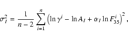
Figure 3 presents a logarithmic plot of ![]() versus
versus
![]() for all of the 911 data points.
for all of the 911 data points.
![\begin{figure}
\par\includegraphics[width=7.5cm,clip]{1367fig3.eps}\end{figure}](/articles/aa/full/2004/42/aa1367/img33.gif) |
Figure 3:
Plot of |
| Open with DEXTER | |
The overall behavior of the plot in Fig. 3 results from
the superposition of points from different flares.
We now want to look in some more detail at the behavior of single flares.
Figure 4 gives the time evolution of ![]() and F35 for
4 flares.
and F35 for
4 flares.
![\begin{figure}
\par\includegraphics[width=16.7cm,clip]{1367fig4.eps}\end{figure}](/articles/aa/full/2004/42/aa1367/img47.gif) |
Figure 4:
Time evolution of the photon spectral index |
| Open with DEXTER | |
 |
(4) |
Figure 5
![\begin{figure}
\par\includegraphics[width=16.7cm,clip]{1367fig5.eps}\end{figure}](/articles/aa/full/2004/42/aa1367/img56.gif) |
Figure 5:
Spectral index |
| Open with DEXTER | |
We show the distribution of the slope of the fitted lines in
Fig. 6.
![\begin{figure}
\par\includegraphics[width=7.5cm,clip]{1367fig6.eps}\end{figure}](/articles/aa/full/2004/42/aa1367/img57.gif) |
Figure 6: Distribution of the linear regression slopes for the rise and decay phases. The average value is marked by the dashed line. |
| Open with DEXTER | |
| (5) |
| (6) |
The difference in averages is about 5 times the standard errors of the mean, and therefore the difference between the two cases is statistically significant. We see that for most of the rise phases there is a soft-hard trend (negative slope) and for most of the decay phases there is a hard-soft trend (also described by a negative slope). The number of rise phases with slope smaller than 0.04 are 5 out of 70, and the number of decay phases with slope smaller than 0.04 are 2 out of 71. Therefore the SHS behavior is a nearly universal trend in peaks of non-thermal emission.
We also investigated whether there is a significant delay in the
correlation of
![]() and
and ![]() .
We defined the delay as the time of the minimum of the quadratic
interpolation curve going through the 3 cross-correlation coefficients
corresponding to a lag of -1, 0 and 1 time bins of about 4 s.
The interpolation enhances considerably the time resolution, as the
noise is small. The distribution of the delays is relatively broad,
centered at -0.32 s, with a standard deviation of 1.1 s and
with extreme delays up to
.
We defined the delay as the time of the minimum of the quadratic
interpolation curve going through the 3 cross-correlation coefficients
corresponding to a lag of -1, 0 and 1 time bins of about 4 s.
The interpolation enhances considerably the time resolution, as the
noise is small. The distribution of the delays is relatively broad,
centered at -0.32 s, with a standard deviation of 1.1 s and
with extreme delays up to ![]() s.
The average of the delays does not significantly differ from 0 since
the standard error of the mean is
s.
The average of the delays does not significantly differ from 0 since
the standard error of the mean is ![]() s.
s.
Furthermore, we tried to see if there is any evidence in the data
for the presence of a pivot point, i.e. a fixed point with coordinates
(E*,F*) common to all the spectra in a rise/decay phase.
We note that such a concept corresponds to a model that does not
yield a power-law dependence of
![]() and
and ![]() ,
but instead
,
but instead
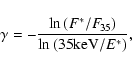 |
(7) |
The power-law model for the ![]() -
-
![]() relation is admittedly very
simple, yet it provides a good empirical description of the observed
quantities.
The range of validity of the model is limited at very high flux
values, since
relation is admittedly very
simple, yet it provides a good empirical description of the observed
quantities.
The range of validity of the model is limited at very high flux
values, since ![]() has a theoretical lower limit at roughly 1.4,
given by the bremsstrahlung of a monoenergetic beam.
Its major disadvantage is the arbitrary assumption of a
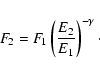
normalization energy, here 35 keV. How do the results shown in Sect. 3 depend on the choice
has a theoretical lower limit at roughly 1.4,
given by the bremsstrahlung of a monoenergetic beam.
Its major disadvantage is the arbitrary assumption of a
normalization energy, here 35 keV. How do the results shown in Sect. 3 depend on the choice
![]() ?
?
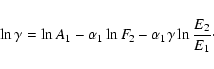
Let E1 and
![]() be two normalization energies.
The normalization coefficients
be two normalization energies.
The normalization coefficients
![]() and
and
![]() satisfy
satisfy
 |
(10) |
 |
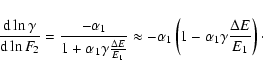
(12) |
For
![]() the relation between
the relation between
![]() and ln
and ln
![]() is still approximately linear but flatter than for
is still approximately linear but flatter than for
![]() if
if
![]() .
This is confirmed in Fig. 7, where the
.
This is confirmed in Fig. 7, where the ![]() vs.
vs.
![]() relation is shown for different normalization energies E0.
In Fig. 7 the
relation is shown for different normalization energies E0.
In Fig. 7 the ![]() -
-![]() relation is presented
according to Eq. (9). In the course of a subpeak the spectral
index and flux move approximately on one of the lines according to the
given normalization energy, assuming the relation (2).
The relation steepens with decreasing normalization energy E0
and finally turns over. In a model with a pivot point at energy E*the
relation is presented
according to Eq. (9). In the course of a subpeak the spectral
index and flux move approximately on one of the lines according to the
given normalization energy, assuming the relation (2).
The relation steepens with decreasing normalization energy E0
and finally turns over. In a model with a pivot point at energy E*the ![]() -
-
![]() relation would be a vertical line for E=E*.
relation would be a vertical line for E=E*.
![\begin{figure}
\par\includegraphics[width=8.4cm,clip]{1367fig7.eps}\end{figure}](/articles/aa/full/2004/42/aa1367/img83.gif) |
Figure 7:
The lines shown here models the relation between the spectral
index |
| Open with DEXTER | |
The final goal (not part of this paper) is the comparison of these results with
the prediction of theoretical models for the energy distribution of accelerated
electrons. For this purpose the electron distribution needs to be reconstructed
from the observed photon spectrum. As an example, the analytically solvable
thick target impact model using the non-relativistic Bethe-Heitler cross
section (Brown 1971; Tandberg-Hanssen & Emslie
1988) predicts that an electron power-law distribution
![]() [electrons
[electrons
![]()
![]() ]
generates a photon spectrum
]
generates a photon spectrum
![]() [photons
[photons
![]()
![]()
![]() ]
with
]
with
| (13) |
 |
(15) |
This study of the ![]() -
-![]() relation in the evolution of the
non-thermal
component of impulsive solar flare hard X-ray emissions exploits the high
spectral resolution of the RHESSI germanium detectors. Contrary to earlier
investigations, the spectral index is not derived from the ratio of a few
channels, but from fitting the spectrum at relatively low non-thermal energies
where most of the photons are emitted. This method eliminates the influence of
the thermal component and improves considerably the noise on the derived
spectral index (Fig. 1).
relation in the evolution of the
non-thermal
component of impulsive solar flare hard X-ray emissions exploits the high
spectral resolution of the RHESSI germanium detectors. Contrary to earlier
investigations, the spectral index is not derived from the ratio of a few
channels, but from fitting the spectrum at relatively low non-thermal energies
where most of the photons are emitted. This method eliminates the influence of
the thermal component and improves considerably the noise on the derived
spectral index (Fig. 1).
The most surprising result of the improved accuracy is the appearance of the
soft-hard-soft behavior on short time scales. The SHS behavior is a feature
seen in nearly all of the non-thermal emission peaks of M-class solar flares.
Whereas SHS was previously considered to be a global property of flares,
Figs. 2 and 4
demonstrate that SHS is a predominantly short-scale phenomenon.
This is the reason why the scatter in the ![]() -
-
![]() plot diminishes when rise and decay phases of individual subpeaks
are analyzed separately.
plot diminishes when rise and decay phases of individual subpeaks
are analyzed separately.
The novel quantitative analysis of the ![]() -
-
![]() relation
has also revealed remarkable properties.
The relation appears linear in double-logarithmic representation
(Fig. 3). Thus it follows an approximate power law,
relation
has also revealed remarkable properties.
The relation appears linear in double-logarithmic representation
(Fig. 3). Thus it follows an approximate power law,
![]() .
Its average index
.
Its average index ![]() is
is
![]() .
The scatter is greatly reduced if individual subpeaks are studied
(Fig. 5).
In the rise phase of individual flare elements, the average index
.
The scatter is greatly reduced if individual subpeaks are studied
(Fig. 5).
In the rise phase of individual flare elements, the average index
![]() is significantly smaller than the index of the
decay phase
is significantly smaller than the index of the
decay phase
![]() (Fig. 6).
The path of a subpeak in the
(Fig. 6).
The path of a subpeak in the ![]() -
-
![]() plot (Fig. 5)
follows tendentially a slanted V, with the rise phase forming the
flatter leg.
This amounts to a secondary trend, superimposed on the SHS behaviour,
of a general spectral softening of the non-thermal component in the
course of a subpeak.
plot (Fig. 5)
follows tendentially a slanted V, with the rise phase forming the
flatter leg.
This amounts to a secondary trend, superimposed on the SHS behaviour,
of a general spectral softening of the non-thermal component in the
course of a subpeak.
The SHS behavior supports the idea that each non-thermal emission peak
represents a distinct acceleration event of the electrons in the flare. The
individual peaks mainly differ by their value for A in the
![]() relation, presumably due to different physical
parameters in the acceleration region.
relation, presumably due to different physical
parameters in the acceleration region.
It is possible to visualize the ![]() -
-
![]() relation by a pivot
point in the
non-thermal spectrum. This point is relatively stable in energy and flux.
The pivot energy was determined as 9 keV in the average with a half-power
distribution of 6.5-12.5 keV. In the course of a peak, the non-thermal
spectrum rises by turning around the pivot point, decreasing
relation by a pivot
point in the
non-thermal spectrum. This point is relatively stable in energy and flux.
The pivot energy was determined as 9 keV in the average with a half-power
distribution of 6.5-12.5 keV. In the course of a peak, the non-thermal
spectrum rises by turning around the pivot point, decreasing ![]() and
increasing the flux beyond the energy of the pivot point. In the decay phase
the spectrum decreases and turns the opposite way. The picture is supported by
the observations of no delay (in the average). We note, however, that the pivot
point model is only an approximation and needs to be further investigated.
and
increasing the flux beyond the energy of the pivot point. In the decay phase
the spectrum decreases and turns the opposite way. The picture is supported by
the observations of no delay (in the average). We note, however, that the pivot
point model is only an approximation and needs to be further investigated.
The SHS phenomenon of flares, and in particular of subpeaks, contradicts the idea of the statistical flare in avalanche models (Lu & Hamilton 1991), assuming that each flare and subpeak is composed of many identical elements that are far below resolution. The superposition of such subresolution structures in a straightforward avalanche process would not yield the observed SHS time behavior.
The subpeaks defined by the SHS behavior thus may be considered as irreducible flare elements. They have durations of one minute (Fig. 2) to shorter than 8 s, the lower limit given by the time resolution (Fig. 4). The close correlation suggests that there is an intrinsic dependence between the flux and energy distribution of electrons for any given elementary acceleration event. If this is the case, it implies that individual SHS structures cannot be further resolved, thus form the elementary structures of flares.
Acknowledgements
The analysis of RHESSI data at ETH Zurich is partially supported by the Swiss National Science Foundation (grant No. 20-67995.02). This work relied on the RHESSI Experimental Data Center (HEDC) supported by ETH Zurich (grant TH-W1/99-2). We thank the many people who have contributed to the successful operation of RHESSI. We acknowledge the contribution of D. Buser, who has prepared the ground for this work in his Diploma Thesis (2003). We thank P. Saint-Hilaire, K. Arzner, S. Krucker, R. Schwartz and H. Hudson for helpful discussions, and the referee for constructive comments.