A&A 423, 267-279 (2004)
DOI: 10.1051/0004-6361:200400030
Line profile variations in WR+O binary systems
I. The code and basic predictions
L. N. Georgiev1 - G. Koenigsberger2
1 - Instituto de Astronomía, Universidad Nacional Autónoma de
México, México
2 - Centro de Ciencias Físicas, Universidad Nacional Autónoma de
México, México
Received 7 January 2003 / Accepted 13 January 2004
Abstract
We compute the P Cyg line profiles formed by the stellar winds of
binary systems containing a Wolf-Rayet and an O-type star, incorporating
the effects due to wind eclipses and wind-wind collisions. The
contribution from both stellar winds to the P Cygni
emission lines is modeled for different orbital phases.
The opacity and the source function are calculated assuming a
simplified atom and the Sobolev approximation, and the emission-line profile
is calculated by exact radiative transfer through the 3D geometry wind.
We analyze the cases of a P Cygni line that is formed only in the
WR wind, and the case of a line formed in both the WR and the O-star
winds. The line-profile variations that are predicted by this model are
presented. When compared with observations, the synthetic profiles and their
phase-dependent variability provide an estimate for the opening angle
of the WWC shock cone and the velocity law of both stellar winds.
Ultraviolet (UV) observations of the binary system
 Vel are used to illustrate how the model predictions can be applied
to the observational data.
Vel are used to illustrate how the model predictions can be applied
to the observational data.
Key words: line: formation - line: profiles - radiative transfer - stars: binaries: general - stars: Wolf-Rayet
Massive stars are responsible for the heavy-element enrichment of the early
Universe and a significant fraction of the enrichment in the present-day Universe.
Their presence marks sites of recent star formation, and they are involved in such
interesting observable phenomena as supernovae, massive X-ray black hole
binary systems and certain classes of gamma ray bursts. Thus, a detailed
understanding of these stars is most desirable and particularly the determination of their
fundamental parameters such as mass, mass-loss rate and effective temperature. The most
direct method for obtaining stellar masses is through the solution of the radial
velocity curves in binary systems, which assumes that the spectral lines are Doppler
shifted exclusively by the projected orbital motion of the stars. However, massive
binaries, and especially those containing Wolf-Rayet (WR) stars, are well-known to
display line-profile variability. The distortion of the line profiles can lead
to fictitious RV measurements.
The two principal mechanisms that are currently believed to produce the dominant
phase-dependent line profile variability are wind-wind collisions (WWC) and wind
eclipses. Koenigsberger & Auer (1985) found observational evidence for both of these
effects in ultraviolet (UV) spectra of 5 WR+O binary systems, concluding, however, that the
effects due to wind eclipses are the dominant ones.
This led them to construct a model to compute the variability under this assumption
(Auer & Koenigsberger 1994), and they were able to reproduce the general trends
in the observed line-profile variability of the N IV 1718 Å line in the
WR+O binary system V444 Cyg. The discrepancies between the model and the
observations were attributed to WWCs. However, the primary objective of these
calculations was to determine the velocity law in the WR wind, using the companion
O-star's continuum emission as a probe. The main conclusion of this study was that
the acceleration of the WR wind occurs over larger distances than predicted
by the standard  velocity laws with
 .
This result is a subject of debate
because, among other reasons, the model assumes that the variability results only from the
absorption of O-star continuum radiation as it passes through a spherically
symmetric WR wind. Massive stars have dense (
.
This result is a subject of debate
because, among other reasons, the model assumes that the variability results only from the
absorption of O-star continuum radiation as it passes through a spherically
symmetric WR wind. Massive stars have dense (
 yr-1) and fast
(
yr-1) and fast
(
 km s-1) stellar winds, and when two such winds interact,
the symmetry is broken. Furthermore, the region in which the WWC occurs can itself
be a source of line emission that will be observed to vary as a function of
orbital phase. Hence, a complete study of the line profile variability requires
a model in which the emission from both stellar winds is calculated
and which includes the proper geometry and emitting characteristics of the interaction region.
km s-1) stellar winds, and when two such winds interact,
the symmetry is broken. Furthermore, the region in which the WWC occurs can itself
be a source of line emission that will be observed to vary as a function of
orbital phase. Hence, a complete study of the line profile variability requires
a model in which the emission from both stellar winds is calculated
and which includes the proper geometry and emitting characteristics of the interaction region.
The geometry for the WWC interaction and its X-ray emitting characteristics
have been the subject of numerous theoretical studies
(Canto et al. 1996; Walder et al. 1999; Stevens et al. 1992; Prilutskii & Usov 1976; Myasnikov et al. 1998; Pittard & Stevens 1999; Luo et al. 1990)
as well as intensive observational campaigns (see van der Hucht et al. 1991
and Moffat 2002 for an overview). However, there is as yet no simple answer
to the question of what geometry should be used when modeling
the line-profile emission from a WWC binary system, nor is it clear to what
degree the WWC region is affecting the optical and UV emission lines
(Flores et al. 2001; Zhekov 2002; Marchenko et al. 1997,1994).
The simplest models for
calculating the line-profile variability assume that the WWC shock cone
is responsible for a pre-specified amount of emission line flux which is
superposed on a broad, underlying emission feature arising in the
WR star wind (Luhrs 1995). The radiative transfer is not treated. Others
recognize that the WWC shock cone that winds around the O-type
star carves out a "hole" in the WR-star wind. The line profile variability
is computed from this non-spherically symmetric wind, combined with an assumption for
the emission arising in the WWC shock cone (Kurosawa et al. 2002; Pittard & Stevens 1999).
Stevens (1993) presented a model that computes the
radiative transfer through both the distorted WR-star wind and the O-star wind
which is confined within the WWC shock cone. He computed the
equivalent widths of the emission and absorption components of P Cygni features,
and compared the results with the observations of the WN5+O6 binary V444 Cyg,
finding good agreement.
In this paper, we follow the approach of Stevens (1993) and we present a
model that calculates the P Cygni line profiles produced by the non-spherical
wind distributions that result from the WWC. This allows a comparison with
emission lines that arise in both the WR and the O-star winds. Section 2 contains
the description of the model; Sect. 3, the predicted line profile variations, and
their dependence on some of the stellar parameters and the shape of the WWC region;
Sect. 4 presents a comparison between the model predictions and the UV observations
of the WC+O binary system Vel; and Sect. 5 presents the
conclusions.
The model contains three main and almost independent parts. The first
part calculates the opacity and the source function of the line(s); the second
part calculates the position and the shape of the contact discontinuity
surface; and the third part performs the formal solution of the equation of
radiative transfer in a 3D geometry.
The calculation of the source function for each of the stars is initially made
under the assumption that the wind has an intrinsically spherically symmetric
distribution of density, temperature and velocity field. The presence of the other
star is ignored.
For each wind, the velocity field v(r) is assumed to obey the standard
-velocity law,
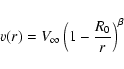 |
(1) |
where  is the terminal velocity of the wind and R0 is defined by
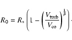 |
(2) |
Here  is the radius of the continuum forming core and
 is the velocity dispersion in the wind
usually called "turbulent velocity".
has values in the range 100-300 km s-1(Groenewegen & Lamers 1989), much higher than the sound speed in the wind and cannot
be due to the real turbulence.
The nature of this velocity dispersion is not clear, but it is probably related to the
instabilities and shocks in the wind (Lamers et al. 1999; Groenewegen & Lamers 1989).
The parameter R0 is chosen so the wind velocity v(r) is equal to
at
is the velocity dispersion in the wind
usually called "turbulent velocity".
has values in the range 100-300 km s-1(Groenewegen & Lamers 1989), much higher than the sound speed in the wind and cannot
be due to the real turbulence.
The nature of this velocity dispersion is not clear, but it is probably related to the
instabilities and shocks in the wind (Lamers et al. 1999; Groenewegen & Lamers 1989).
The parameter R0 is chosen so the wind velocity v(r) is equal to
at  which is the innermost point considered in the code.
This velocity field, combined with the mass loss rate  ,
defines the density
distribution
,
defines the density
distribution  .
The continuum opacity
.
The continuum opacity
 is assumed to be gray and
proportional to the electron density
is assumed to be gray and
proportional to the electron density  ,
which, in turn, is proportional to .
This assumption is equivalent to assuming the absence of a strong
gradient in the degree of ionization for the major electron contributors (H and He ). The continuum radiation field is calculated using a
local approximated
,
which, in turn, is proportional to .
This assumption is equivalent to assuming the absence of a strong
gradient in the degree of ionization for the major electron contributors (H and He ). The continuum radiation field is calculated using a
local approximated  operator (Olson et al. 1986) with Ng acceleration (Olson et al. 1986; Ng 1974). The test runs
show that our average intensity plotted as a function of radius matches the
analytical solution of Hummer & Rybicki (1971) to better than 1% error.
operator (Olson et al. 1986) with Ng acceleration (Olson et al. 1986; Ng 1974). The test runs
show that our average intensity plotted as a function of radius matches the
analytical solution of Hummer & Rybicki (1971) to better than 1% error.
Lamers et al. (1987) proposed a useful characterization of the distribution
of the line opacity
 valid for resonance lines in stellar winds. Olson (1981)
proposed an analytical estimate
for lines originated from
the upper level of the resonant lines ("resonant lines of excited
levels"). We combine these two analytical approaches to estimate the opacity, avoiding
a very time-consuming full solution. The line source function
valid for resonance lines in stellar winds. Olson (1981)
proposed an analytical estimate
for lines originated from
the upper level of the resonant lines ("resonant lines of excited
levels"). We combine these two analytical approaches to estimate the opacity, avoiding
a very time-consuming full solution. The line source function
 is calculated in
the Sobolev approximation (Sobolev 1960) corrected for the presence of the
continuum as in (Hummer & Rybicki 1985). Most of the
strong UV resonance lines are doublets and we need to treat them accordingly.
We calculate the source function for the doublets following Olson (1982).
The tests reproduce very well the source function given by this author.
is calculated in
the Sobolev approximation (Sobolev 1960) corrected for the presence of the
continuum as in (Hummer & Rybicki 1985). Most of the
strong UV resonance lines are doublets and we need to treat them accordingly.
We calculate the source function for the doublets following Olson (1982).
The tests reproduce very well the source function given by this author.
Both scattering and collisional processes are taken into account
in the source function, but the parametrization of the optical depth is valid for
resonance lines, so the scattering term dominates.
In the second part of the code the shape of the contact discontinuity surface is
calculated. There are at least two analytical solutions for the shape of these surfaces
(Canto et al. 1996; Stevens et al. 1992; Luo et al. 1990). However,
all of these solutions assume that the winds have attained their terminal velocities,
an assumption that may not be adequate in the case of close
binary systems. That is, the winds of both stars may be still accelerating at
the position of the stagnation point. Thus, we have
generalized the method of Stevens et al. (1992) so as to include
the possibility that the winds collide before they have reached the
terminal speeds. The position of the stagnation point (r=r0) is found from the
numerical solution of the equation of the momentum balance along
the line connecting the two stars:
![\begin{displaymath}\left[\dot{M}_1 v_1(r)\right]^{1/2} = \left[\dot{M}_2 v_2(r)\right]^{1/2} = \Re.
\end{displaymath}](/articles/aa/full/2004/31/aa3465/img27.gif) |
(3) |
Following the same arithmetic as Stevens et al. (1992) and
Luo et al. (1990), but with both
velocities depending on the distance to the stars, we obtain a differential
equation for the shape of the discontinuity surface (same as Eq. (4) of
Stevens et al. 1992, but with  depending on r).
The numerical solution of this equation gives the shape of the surface. Clearly,
this is a highly idealized model for the WWC region, and it probably differs
significantly from that which applies to real systems. For example,
Stevens et al. (1992) performed an in-depth study
of the dynamics of the stellar wind and shock structure using a 2D hydrodynamics code
which accounts for radiative cooling self-consistently, and found that Kelvin-Helmholtz
instabilities develop whenever the wind velocities of the two stars are not equal.
Furthermore, there is a rapid growth of dynamical instabilities when radiative
cooling is important in the flow. The importance of cooling is characterized by
the parameter
depending on r).
The numerical solution of this equation gives the shape of the surface. Clearly,
this is a highly idealized model for the WWC region, and it probably differs
significantly from that which applies to real systems. For example,
Stevens et al. (1992) performed an in-depth study
of the dynamics of the stellar wind and shock structure using a 2D hydrodynamics code
which accounts for radiative cooling self-consistently, and found that Kelvin-Helmholtz
instabilities develop whenever the wind velocities of the two stars are not equal.
Furthermore, there is a rapid growth of dynamical instabilities when radiative
cooling is important in the flow. The importance of cooling is characterized by
the parameter  (Stevens et al. 1992).
If
(Stevens et al. 1992).
If  ,
the shock region is isothermal and can radiatively cool in an efficient
manner. In long-period binary systems, the post shock flow will tend to be more
adiabatic, although if one of the companions is a WR star,
the flow along the WR wind shock will remain radiative. In eccentric systems,
such as
Vel, the degree of cooling and the resultant shock structure for the
WR wind will differ substantially throughout the orbit.
,
the shock region is isothermal and can radiatively cool in an efficient
manner. In long-period binary systems, the post shock flow will tend to be more
adiabatic, although if one of the companions is a WR star,
the flow along the WR wind shock will remain radiative. In eccentric systems,
such as
Vel, the degree of cooling and the resultant shock structure for the
WR wind will differ substantially throughout the orbit.
There are several additional factors that may influence the shape of the WWC region.
Because both stars in the WR+O binary systems have radiation-driven
winds, it is possible for the radiation field of
the O-type star to slow the flow of the approaching WR wind before the wind-wind interaction
region is reached.
This potentially important mechanism is termed "radiative braking"
(Gayley et al. 1997; Owocki & Gayley 1995).
Hence, the WWC may occur at significantly lower
wind velocities, completely modifying the geometry of the shock cone region
from that derived under the assumption that both stellar winds collide
at their unperturbed velocities. Furthermore, the ionization structure
of the approaching stellar wind may also be modified, leading to different
emission-line characteristics in the regions of the stellar wind that
face the companion, compared to the unperturbed case.
The calculation of these effects requires the solution of the radiative
transfer in conjunction with the hydrodynamic equations, which goes beyond
the scope of the present investigation. However, by comparing the
observed line profiles and their variability with the theoretically predicted
profiles from our simple code, the relative importance of
these additional mechanisms may be determined.
Other phenomena that may be present in the stellar winds, and which we neglect,
include the possible presence of inhomogeneities in the winds
and Coriolis forces. The non-homogeneous nature of the winds (i.e., the so-called
"blobs'', Moffat et al. 1988) is believed to be due to radiative instabilities
that lead to embedded shocks (Owocki & Rybicki 1991). Given
the stochastic nature of the inhomogeneities, phase-dependent line profile
variability is not expected to be produced by this phenomenon,
unless the external irradiation modifies the
source of the inhomogeneities. Coriolis forces are expected to distort the
geometry of the wind-wind collision region from that which is computed
under the assumption that the interaction occurs in a non-rotating
reference frame. In general, the ram pressure
equilibrium between the WR wind and the O-star wind is such that the shock cone
wraps around the O-type star and is tilted with respect to the axis joining the
two stars by an angle that, for small values of the ratio
 ,
can be approximated with
,
can be approximated with
 (
).
(
).
Our justifications for using an idealized model for the WWC region is that, for
the present calculations, the WWC is simply a boundary between the WR star and the
O-star winds, and we intend to understand the way in which the radiative transfer
through each of the two winds leads to line-profile variability. The potential
contribution from a time-varying, line-emitting boundary may be incorporated in
future studies.
The third part of the code performs the radiation transfer and produces the
emergent spectrum. Our method differs significantly from that used by
Stevens (1993), but as we shall show below, reproduces some of his
results.
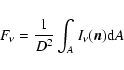
The flux detected by an observer is the integral of the specific monochromatic
intensity that the object emits in the direction of the observer
 over the area A of the projection of the object on the plane of the sky:
 |
(4) |
where D is the distance to the object,  is the unit
vector defining the direction to the observer, and dA is the unit surface
perpendicular to .
is the unit
vector defining the direction to the observer, and dA is the unit surface
perpendicular to .
The surface A for a binary system is the projection on the plane of the sky
of a sphere that is large enough to surround the entire system, and which
includes the predominant emitting regions of both winds. The integration
over A is performed using a Monte-Carlo algorithm
which adapts the distribution of random points inside A so
that the parts of the wind with predominant emission are better sampled.
At each such point on the surface A a ray in the direction of the observer is
created. This ray crosses the winds, and the emergent intensity is calculated as a
formal solution of the equation of radiative transport along this ray.
![\begin{figure}
\par\includegraphics[width=7cm,clip]{lgeorgiev_fig1.eps}
\end{figure}](/articles/aa/full/2004/31/aa3465/Timg36.gif) |
Figure 1:
Definition of the physical parameters along a
line of sight used for the formal solution of the equation of
radiative transport. |
| Open with DEXTER |
Once created, the ray is divided into intervals. For any interval of the ray
(Fig. 1), one can write
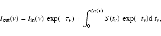 |
(5) |
where S is the source function,
 is the optical depth
between the ends of the interval under consideration for the given frequency,
and
is the optical depth
between the ends of the interval under consideration for the given frequency,
and
 and
and
 are the intensities that enter and exit the interval, respectively; i.e.,
the input and output intensities. At the furthermost end of the ray
are the intensities that enter and exit the interval, respectively; i.e.,
the input and output intensities. At the furthermost end of the ray
 (no incident radiation enters the system). Then Eq. (5)
can be applied to the consecutive intervals until the nearest end of the ray is reached.
The
at this point is the emergent intensity needed for the profile
calculation (Eq. (4)).
(no incident radiation enters the system). Then Eq. (5)
can be applied to the consecutive intervals until the nearest end of the ray is reached.
The
at this point is the emergent intensity needed for the profile
calculation (Eq. (4)).
The source function and the opacity are interpolated along the ray using
a monotonic cubic interpolation (Steffen 1990). The
optical depth for each interval is calculated with
 |
(6) |
where l0 and l1 are the coordinates along the ray at the points 0 and 1, as illustrated in Fig. 1. The integration is performed
along the ray.
Once
is calculated, the source function
 is
interpolated with a quadratic polynomial
is
interpolated with a quadratic polynomial  using the values S0, S1 and S2 at the points that are numbered 0,1 and 2 (Fig. 1).
 |
|
|
(7) |
Substituting this into Eq. (5)
 (
( )
adopts the form
)
adopts the form
 |
(8) |
where the Si are the values of the source function at the
points 0,1 and 2 and the weights wi are calculated from
 |
(9) |
The solution (8) can be applied for consecutive spatial intervals along
a given ray.
For each spatial interval, the corresponding velocity interval is calculated. The
output intensity
is calculated and then used as the input intensity
 for the
next interval. The process starts at the boundary of the wind which is furthest
from the observer, and continues step by step until the opposite boundary is
reached. If the ray crosses the wind-wind collision region, then
the intensity emerging from one wind
is used as the boundary condition for the other wind, and the procedure is
repeated except that now the velocity field and the physical conditions used
correspond to those of the second wind. Thus, one can describe the process for
calculating the emergent intensity along a ray in terms of "stepping" from
point to point along it. At each step, the output intensity is
calculated using the output intensity of the previous step as
and the values of S,
and vl at the ends of the interval.
for the
next interval. The process starts at the boundary of the wind which is furthest
from the observer, and continues step by step until the opposite boundary is
reached. If the ray crosses the wind-wind collision region, then
the intensity emerging from one wind
is used as the boundary condition for the other wind, and the procedure is
repeated except that now the velocity field and the physical conditions used
correspond to those of the second wind. Thus, one can describe the process for
calculating the emergent intensity along a ray in terms of "stepping" from
point to point along it. At each step, the output intensity is
calculated using the output intensity of the previous step as
and the values of S,
and vl at the ends of the interval.
The method has several advantages over the methods in which the emergent
intensity is computed using the "common velocity surfaces (CVS)".
It is purely local, and it depends
only on the conditions at the points 0,1 and 2. If the velocity field,
source function and opacity do not change rapidly between these points, the
solution is stable. The global geometry of the problem enters the solution
only by means of the interpolation of S,
and the projection of the velocity
field.
In order to avoid a problem at the discontinuity surface, the contact discontinuity surface (CDS) is treated
as a boundary. The radiative transfer along a ray is calculated independently
within each of the two winds and the intensity at the CDS from one wind is treated
as the boundary condition for the second wind.
The other important problem is the connection between the spatial and
frequency grids introduced by the velocity field. For each
spatial interval,  is calculated only for the frequency interval defined by the
difference of the velocities at the ends of the interval. Due to the Doppler shift
between the ends of an interval along a ray, the line opacity for the
rest of the frequencies is very small. If the difference between the intervals
is much larger than the turbulent width of the line (
), the two ends
of the interval are decoupled in frequency space. The resulting emission emerging
from each interval becomes a Gaussian spike which barely overlaps
with the emission from the previous and the next interval of the same ray.
The computed emergent profile has a shape composed of these independent spikes
and differs from the smooth profiles generally observed.
To avoid this problem, we adapt the points along each ray so that the
separation between two consecutive points along it be less than three
times the turbulent velocity.
is calculated only for the frequency interval defined by the
difference of the velocities at the ends of the interval. Due to the Doppler shift
between the ends of an interval along a ray, the line opacity for the
rest of the frequencies is very small. If the difference between the intervals
is much larger than the turbulent width of the line (
), the two ends
of the interval are decoupled in frequency space. The resulting emission emerging
from each interval becomes a Gaussian spike which barely overlaps
with the emission from the previous and the next interval of the same ray.
The computed emergent profile has a shape composed of these independent spikes
and differs from the smooth profiles generally observed.
To avoid this problem, we adapt the points along each ray so that the
separation between two consecutive points along it be less than three
times the turbulent velocity.
As a test, the line profiles for singlets and doublets calculated with our code
were compared with those calculated by the SEI method (Lamers et al. 1987)
and the results are practically identical.
Consider a WR+O binary system with a circular orbit such that the O-star
is embedded in the WR wind. We will illustrate the effects on the line
profiles
due to the following: 1) the occultation
of the O-star by the WR wind ("wind eclipse") only; and 2) wind eclipse plus
the presence of a WWC shock cone that folds around the O-star. We will
consider two cases: 1) the line being formed only in the WR wind; and 2) the
line
being formed in both winds. We will illustrate the orbital
phase-dependent variations that these effects have on the line profiles.
Phase  is defined to be when the O star is on the near side
(i.e., "in front" of the WR, with respect to the observer). We will analyze
3 phases: one just after the eclipse of the WR by the O-star (
is defined to be when the O star is on the near side
(i.e., "in front" of the WR, with respect to the observer). We will analyze
3 phases: one just after the eclipse of the WR by the O-star ( );
the second at the quadrature (
);
the second at the quadrature ( ); and the third just before the
eclipse of the O-star by the WR (
); and the third just before the
eclipse of the O-star by the WR ( ). The parameters used in the
test profiles are summarized in Table 1.
). The parameters used in the
test profiles are summarized in Table 1.
Table 1:
Parameters of the wind used for the test profiles.
3.1 Line formed in the WR wind only
Consider a line that is formed in the WR wind but not in the
O-star wind such as CIII] 1909 Å in WC stars. Let us
assume (momentarily) that there is no interaction between the winds of the two stars. The parameters used for the lines discussed below are typical of a UV resonance line but the general conclusions are valid for any line which shows
a P Cyg type profile.
The first effect on the line profile that we consider is the wind eclipse of
the O-star by the WR wind, as a function of orbital phase. The predicted
line-profile variations are illustrated in Fig. 2.
At ,
the portion of WR wind that lies outside of the O-star
orbit, along the line-of-sight to the O-star, will produce an additional
absorption in the line profile, superimposed on the intrinsic WR P Cyg
absorption. Clearly, this is not a realistic situation. The space
beyond the O-star orbit, along the line-of-sight to the O-star should be filled
with O-star wind. But, this part of the wind is not there because we are ignoring for the moment the
interaction between the two winds. This artificial feature
helps to illustrate the way in which the wind eclipse affects the line
profile.
The blue wing of this feature is almost as extended as that of the
WR star. When the O star moves in its orbit to
and beyond, the
extra absorption extends toward the red, and starts to "eat into" the emission
component, until it has extended to nearly the full width of the emission
at
.
This is because the O-star is on the far side
of the WR wind, and the full range of WR wind velocities is projected onto
the O-star, producing absorption. At this point, the emission line is
practically
reduced to the continuum level. The important point to note is that
the blue edge of the P Cyg absorption component never changes its velocity,
remaining always at the
of the WR wind.
The emission component varies as was described by Stevens (1993)
and Auer & Koenigsberger (1994)
caused by the wind eclipse. When the O star is occulted by part of the WR wind,
an additional absorption component decreases the contribution of the O star
to the total luminosity of the system. The extent to the red of this
additional absorption reflects the projected velocity of the WR wind along
the line of sight to the O-star. Auer & Koenigsberger (1994) found a discrepancy
between the predicted absorption (assuming only wind eclipses)
and the IUE observations of V444 Cyg, and attributed this difference to the
presence of the WWC.
![\begin{figure}
\par\includegraphics[width=5.5cm,clip]{lgeorgiev_fig3a.eps}
\end{figure}](/articles/aa/full/2004/31/aa3465/Timg61.gif) |
Figure 2:
Line profile variations assuming only wind eclipses.
The dashed line is the profile computed for an equivalent
spherically symmetric wind with no binary interaction effects. The profiles
are labeled with the corresponding orbital phases. |
| Open with DEXTER |
![\begin{figure}
\par\includegraphics[width=16cm,clip]{lgeorgiev_fig3b.eps}
\end{figure}](/articles/aa/full/2004/31/aa3465/Timg62.gif) |
Figure 3:
Line profile variations including the effects of a WWC shock cone filled
with optically thin O-star wind at different orbital phases. The corresponding common
velocity surfaces, as viewed from a location perpendicular to the orbital
plane, are plotted at 0.1, 0.3, 0.5, 0.7, and 0.9 .
The WR star is at the origin of the coordinate system (distance in  )
and the dot-dash lines indicate the column of wind material along the
line-of-sight to the O-star from an observer located at
the bottom of the page. The dashed line-profile is that produced in an
equivalent, spherically symmetric wind with no binary interaction effects. )
and the dot-dash lines indicate the column of wind material along the
line-of-sight to the O-star from an observer located at
the bottom of the page. The dashed line-profile is that produced in an
equivalent, spherically symmetric wind with no binary interaction effects. |
| Open with DEXTER |
The effects that result from the inclusion of the WWC region are illustrated
in Fig. 3. The first point to note is that
the O-star wind is, by construction, optically thin for the line we are considering.
Thus, the WWC cone that folds around the O-star can be thought of as a "hole" in
the WR's extended emitting region, thus introducing the departure from spherical
symmetry. At ,
we view the WR wind through this "hole". However,
because of the presence of the WWC region, the WR wind is being stopped by the O-star
wind and does not achieve its terminal speed, leading to a P Cyg absorption
component with a less extended blue edge than the unperturbed wind (Fig. 3, upper left
panel). At
 ,
the absorption edge has returned to ,
as
the "hole" moves away from the line-of-sight. At phase ,
part of the WR emission at the central wavelengths, produced in the WR wind moving
perpendicular to the line-of-sight (where the "hole" is) is missing Fig. 3, upper right
panel). This
produces the slight decrease of the emission with respect to the same line
formed in a spherically symmetric wind. The amplitude of this variation is
proportional to the volume of the line forming region which is removed by the
O-star wind. Part of the WR wind is projected in from of the O star. As in the case
of pure wind eclipse the absorption component of the profile became deeper.
At ,
the "hole" is on the back-side of the WR,
and now it is the red portion of the emission line which is decreased, both
in intensity (due to the absence of emitting material at these velocities)
and in velocity (due to the WWC region). The extent of the additional
absorption is smaller than for the case without WWCR because the projection of
the WR wind velocity along the line of sight to the O-star is smaller than
(Fig. 3, lower right panel). Thus, the presence of a WWC introduces phase-dependent variability
in the blue edge of the P Cyg profile and decreases the intensity of the
emission line red wing.
,
the absorption edge has returned to ,
as
the "hole" moves away from the line-of-sight. At phase ,
part of the WR emission at the central wavelengths, produced in the WR wind moving
perpendicular to the line-of-sight (where the "hole" is) is missing Fig. 3, upper right
panel). This
produces the slight decrease of the emission with respect to the same line
formed in a spherically symmetric wind. The amplitude of this variation is
proportional to the volume of the line forming region which is removed by the
O-star wind. Part of the WR wind is projected in from of the O star. As in the case
of pure wind eclipse the absorption component of the profile became deeper.
At ,
the "hole" is on the back-side of the WR,
and now it is the red portion of the emission line which is decreased, both
in intensity (due to the absence of emitting material at these velocities)
and in velocity (due to the WWC region). The extent of the additional
absorption is smaller than for the case without WWCR because the projection of
the WR wind velocity along the line of sight to the O-star is smaller than
(Fig. 3, lower right panel). Thus, the presence of a WWC introduces phase-dependent variability
in the blue edge of the P Cyg profile and decreases the intensity of the
emission line red wing.
![\begin{figure}
\par\includegraphics[width=8cm,clip]{lgeorgiev_fig4.ps}
\end{figure}](/articles/aa/full/2004/31/aa3465/Timg64.gif) |
Figure 4:
The velocity of the blue wing measured at level 0.8 of the
continuum for a wind having a velocity law with  .
The arrows
indicate the phases at which the wall of the contact
discontinuity crosses the line of sight. Squares - 70 .
The arrows
indicate the phases at which the wall of the contact
discontinuity crosses the line of sight. Squares - 70 opening
angle; circles - 50.
The O-star is in front for phase 0.0.
opening
angle; circles - 50.
The O-star is in front for phase 0.0. |
| Open with DEXTER |
This effect was also qualitatively described by Shore & Brown (1988)
for V444 Cyg and the absence of part of the dense WR wind is also
inferred from the X-ray variability (Corcoran et al. 1996; Conti et al. 1995).
The degree of variability in the blue wing of the absorption
component is related to the overall geometry of the contact discontinuity
surface. If we assume that (WR) is not reached before the WR wind
interacts with the O-star wind, the maximum velocity of
the WR wind can be viewed by the observer only while the "hole" is away from the
line of sight to the WR continuum-emitting core. At orbital phases when
the "hole" is intersected by the the line-of-sight,
the velocity of the blue wing decreases.
Hence, by measuring the extent of the blue wing, and its behavior as a
function of orbital phase, the opening angle of the WWC shock cone can be
determined. Figure 4 shows the variation of the blue wing velocity
of a line for two shock cone opening angles, 50
and 70.
The variation of the velocity is symmetric with respect to the
phase 0.0. The distorsion of the CDS by other effects will lead to
different variation of the velocity. If the wind is affected by radiative braking,
the CDS will have larger opening angle. The changes in the velocity of the
blue wing will start earlier and finish later than the case discussed above. The Coriolis force tilts
the CDS. Its leading wall comes closer to the star and the trailing wall goes
away from it. Therefore the changes in the blew wing velocity won't be symmetric
with respect to phase
as above. But whatever the shape of the CDS is,
it removes part of the WR wind which inevitably leads to the profile variability described above.
![\begin{figure}
\par\includegraphics[width=8cm,clip]{lgeorgiev_fig5.ps}
\end{figure}](/articles/aa/full/2004/31/aa3465/Timg65.gif) |
Figure 5:
The same as in Fig. 4 (50
shock cone
opening angle only) but for different velocity laws.
Squares -  ;
circles - ;
triangles - ;
circles - ;
triangles -
 .
O star is in front for phase 0.0. .
O star is in front for phase 0.0. |
| Open with DEXTER |
Furthermore, the amplitude of the variation in the blue wing of the
absorption component provides information on the velocity structure
of the wind. If the wind is far from achieving its terminal speed
when the wind-wind collision occurs, then the observed amplitude of the
variation in this wing will be large. Otherwise, it will be smaller. If
the wind has already reached terminal speeds at the CDS, then
no variation should be observed. Thus, the amplitude of the variability is
strongly dependent on the velocity law. Figure 5 shows the
dependence of the amplitude of the variability for three different velocity
laws but with the same opening angle for the colliding winds shock cone.
Hence, the presence of this variability indicates that the wind is still
accelerating at distances where the CDS forms. Note that even if radiative
braking is operating, it is not expected to affect the entire region of the
wind where
has been attained, but only the regions close to the
O-type star. Hence, even in this case, the above-mentioned variability should be
present.
The variability of the equivalent width of the absorption component will
depend on the ratio of the radii of the two stars. Consider an eclipsing
system where the O-star is larger than WR.
At the eclipse when the O star is in front, the absorption component of a line
formed only in the WR wind will disappear, since the O star blocks the
portion of the WR wind where the absorption arises. At the other eclipse,
the absorption will be stronger, because there are two portions of WR wind material projected onto continuum sources: one in front
of the WR stellar core, and the other in front of that part of the O star
disk,
which extends beyond the radius of the WR core. If the absorption component
is seen at all phases, this means that the eclipse of the WR by the O-star
is not total.
![\begin{figure}
\par\includegraphics[width=16cm,clip]{lgeorgiev_fig55.eps}
\end{figure}](/articles/aa/full/2004/31/aa3465/Timg66.gif) |
Figure 6:
Same as Fig. 3, but for the case in which the O-star wind is optically
thick. Note that in this case a wind eclipse occurs near  ,
as well
as around ,
as well
as around  . . |
| Open with DEXTER |
3.2 Line formed in both winds
Consider now a line which is optically thick in both winds, for example
CIV 1550 Å. The profile of such a line is shown in Fig. 6.
There are three major differences with respect to the previous
case. First, because the O-star wind is generally faster than the WR wind, the
velocity of the absorption component's blue wing is now determined mainly
by the O-star wind, at all phases where this star's wind is not
significantly perturbed by the WWC (Fig. 6, profiles at phases ,
and
).
Thus, for velocities between
 and
and
 ,
only the
O-star wind contributes to the absorption component. The figure shows how the
maximal velocity of the O wind projected on the line of sight is reduced, which
causes changes in the velocity of the blue wing of the emitted profile.
For velocities lower than
,
both winds contribute to the absorption component.
,
only the
O-star wind contributes to the absorption component. The figure shows how the
maximal velocity of the O wind projected on the line of sight is reduced, which
causes changes in the velocity of the blue wing of the emitted profile.
For velocities lower than
,
both winds contribute to the absorption component.
![\begin{figure}
\par\includegraphics[width=12cm,clip]{lgeorgiev_fig6.eps}
\end{figure}](/articles/aa/full/2004/31/aa3465/Timg69.gif) |
Figure 7:
Profiles of a line formed in both WR and the O-star winds
at quadrature ()
for different
ratios of the continuum luminosities (indicated above the profiles). The
vertical arrows mark the contributions to the P Cygni profile from
each of the two stars. |
| Open with DEXTER |
Secondly, the depth of the absorption component depends on the continuum
levels of both stars in the system for velocities between
and zero, but only on the continuum level of the O-star between
and
.
Thus, a "step" is present in the P Cygni absorption
component at
(Fig. 6, profiles at phases
and
).
And finally, we see a wind eclipse of the
WR star by the O wind, which reduce the emission at the phases when the O wind is in front
of the WR star (Fig. 6, upper left panel).
The effect of the "step" is illustrated in Fig. 7, where we plot P Cygni
line profiles produced in three binary systems having the same wind structure,
but in which the ratio between the WR and the O-star monochromatic luminosities (
 and
and  ,
respectively) varies between 0.5 and 2.
Similar profiles were obtained by Stevens (1993) in his
model 2c. We emphasize that under the usual assumptions for the structure
of stellar winds, the presence of a step in the blue wing of the
P Cyg profile is a clear evidence of binarity of the object.
,
respectively) varies between 0.5 and 2.
Similar profiles were obtained by Stevens (1993) in his
model 2c. We emphasize that under the usual assumptions for the structure
of stellar winds, the presence of a step in the blue wing of the
P Cyg profile is a clear evidence of binarity of the object.
To quantify the phase-dependent line profile variability in this
case, we measure the velocity of the P Cygni absorption component
throughout an orbital cycle at two positions in its profile
(illustrated by the black dots in the right panel of Fig. 8).
The particular profile illustrated in Fig. 8 corresponds to an
elongation in a system with
 km s-1 and
 km s-1 and where the shock cone opening angle is
  .
The black dots are placed at fixed intensity levels of L=0.8 and 0.4,
with respect to the continuum level. These levels allow us to
follow the behavior of the two portions of the P Cygni absorption which
lie on either side of the step, when it is present. We prefer to measure
the velocity at the wing of the absoption instead of often used
.
The black dots are placed at fixed intensity levels of L=0.8 and 0.4,
with respect to the continuum level. These levels allow us to
follow the behavior of the two portions of the P Cygni absorption which
lie on either side of the step, when it is present. We prefer to measure
the velocity at the wing of the absoption instead of often used
 .
The wind of the profile is better defined in low S/N spectra and can be
measured even for nonsaturated profiles. And also, we are interested on the
variation of the velocity and not of its exact value.
.
The wind of the profile is better defined in low S/N spectra and can be
measured even for nonsaturated profiles. And also, we are interested on the
variation of the velocity and not of its exact value.
The panel on the left in Fig. 8
shows how the velocities vary as a function of orbital phase. At L=0.4,
the O-star wind dominates when it is in front of the WR (orbital phases 0.75-1.25), while at the opposite phases, the WR-star's
wind velocity dominates. The amplitude of the variation is  1500 km s-1.
The portion of the line profile at L=0.8 can be attributed almost
completely to the wind of the O-star, and it shows a small (200 km s-1) decrease in speed
around .
This indicates that the O-star wind encounters the wind-wind
collision region before it achieves its terminal velocity. Hence,
Fig. 8 provides a diagnostic tool for the speed of the O-star
wind just before it collides with the WR-star wind. Slower edge velocities
in the C IV 1550 lines in four of the six WN+O binaries observed with
the IUE by Koenigsberger & Auer (1985) at eclipse phases were interpreted
as due to this effect.
1500 km s-1.
The portion of the line profile at L=0.8 can be attributed almost
completely to the wind of the O-star, and it shows a small (200 km s-1) decrease in speed
around .
This indicates that the O-star wind encounters the wind-wind
collision region before it achieves its terminal velocity. Hence,
Fig. 8 provides a diagnostic tool for the speed of the O-star
wind just before it collides with the WR-star wind. Slower edge velocities
in the C IV 1550 lines in four of the six WN+O binaries observed with
the IUE by Koenigsberger & Auer (1985) at eclipse phases were interpreted
as due to this effect.
![\begin{figure}
\par\includegraphics[width=12.5cm,clip]{lgeorgiev_fig7.eps}
\end{figure}](/articles/aa/full/2004/31/aa3465/Timg77.gif) |
Figure 8:
Left: phase-dependent velocity variations of the two
positions in the blue wing of a P Cygni line that is formed in both the WR
and in the O-star winds. Right: line profile
illustrating the position (black dots) where the measurements
were made, and that were plotted in the left panel. |
| Open with DEXTER |
The effects of the wind eclipse and the wind-wind interaction
can be summarized as follows:
- The wind eclipse creates an additional absorption component with variable
width, depending on the orbital phase. This absorption component acts to reduce the
emission portion of the P Cygni profile, shifting the blue emission wing toward
longer wavelengths. If the O star lies outside the WR-wind line forming region and
the system is eclipsing, the emission component may disappear completely at
conjunction. In non-resonance lines (particularly those observed at optical
wavelengths) the effect is more subtle, and, if unaccounted for, can lead to
significant distortions in the radial velocity curve of emission lines.
- The wind-wind interaction deforms the two winds. The O-star wind
carves out a "hole" in the WR wind. Thus, the volume of WR wind on
the side facing the O-star is reduced. If the "hole" extends all the way to the
accelerating portion of the WR wind, then the velocity of the blue wing
of the lines formed only in the WR will be variable. The amplitude of this
variation provides an estimate of the WR wind velocity law.
The velocity starts to deviate from the
 at the moment when the
leading wall of the CDS crosses the line of sight and returns to
when the trailing wall moves away from the line of sight. This yields
a measure of the opening angle of the CDS.
at the moment when the
leading wall of the CDS crosses the line of sight and returns to
when the trailing wall moves away from the line of sight. This yields
a measure of the opening angle of the CDS.
If a line is formed in both winds it has a step in its blue absorption wing
(Fig. 7). If the line is saturated (as CIV 1550 Å) the position of
the step gives a measure of the ratio of the monochromatic luminosities of the stars at
the line frequency. The wing above the step reflects the changes of the O-star
wind and the wing below the step coresponds to the WR-wind. During the phases
when the O-star is in front, its wind eclipses the WR star and the step
disappears.
The time interval over which the velocity below the step is
 also provides
a measure of the CDS opening angle.
also provides
a measure of the CDS opening angle.
We emphasize that the qualitative effects described above do not
depend on the detailed shape of the contact discontinuity surface.
The profile variability shown will occur in any binary system where the
spherical symmetry of the line-formation regions is broken, and it
can be used to study the geometry of the wind regions. In particular,
the current version of the code neglects the effects of the Coriolis force,
which will modify the axis of symmetry of the WWC shock cone, but the
tilt angle may be determined through a comparison of the predicted and
the observed line-profile variability.
Table 2:
Parameters of
Vel.
The binary system
Vel is an eccentric and relatively long orbital
period binary system containing a WC8 star and an O8 III star (Schaerer et al. 1997).
The IUE archive contains 108 spectra of Vel in
the
 1200-1900 Å range, of which 93 have a good S/N.
These spectra cover the entire orbital period of 78 days.
Its orbital parameters and physical characteristics were derived by
Schmutz et al. (1997); De Marco & Schmutz (1999); De Marco et al. (2000) and are
reproduced here in Table 2. All velocities presented
in the following sections have been corrected for the orbital motion
of the WR star using the parameters from Schmutz et al. (1997).
1200-1900 Å range, of which 93 have a good S/N.
These spectra cover the entire orbital period of 78 days.
Its orbital parameters and physical characteristics were derived by
Schmutz et al. (1997); De Marco & Schmutz (1999); De Marco et al. (2000) and are
reproduced here in Table 2. All velocities presented
in the following sections have been corrected for the orbital motion
of the WR star using the parameters from Schmutz et al. (1997).
The orbital phases are defined so that the periastron passage is at phase
.
The O star is in front at phase  and the WR star is in front at
phase
and the WR star is in front at
phase  .
Note, however, that the system does not eclipse.
The adopted velocities of the two winds are
(De Marco & Schmutz 1999; De Marco et al. 2000)
.
Note, however, that the system does not eclipse.
The adopted velocities of the two winds are
(De Marco & Schmutz 1999; De Marco et al. 2000)
 km s-1 and
 km s-1.
4.1 Line formed in the WC8 wind only
![\begin{figure}
\par\includegraphics[width=7cm,clip]{lgeorgiev_fig8.eps}
\end{figure}](/articles/aa/full/2004/31/aa3465/Timg93.gif) |
Figure 9:
The velocity of the blue wing of the absorption component of the
CIII] 1909 Å line in Vel measured at level 0.8 of the continuum.
The O-star is in front at phase 0.03. |
| Open with DEXTER |
The line C III] 1909 Å is observed only in WR stars and not in O stars.
The lower level of this atomic transition is a meta-stable state, so that
it can be treated as a "resonant line of excited levels". Thus, it should
behave as predicted in Sect. 3.1. In Fig. 9 we plot the
velocity of the "blue" wing of the P Cygni absorption component of this
line, as a function of orbital phase. According to Fig. 4,
the absolute value of the velocity of this feature should decrease when
the O-star is in front (
 )
if the wind-wind collision
occurs in the accelerating portion of the WR wind.
A change from -1550 to -1300 km s-1 does occur between
)
if the wind-wind collision
occurs in the accelerating portion of the WR wind.
A change from -1550 to -1300 km s-1 does occur between
 and
and
 ,
with a return to -1550 km s-1 by
,
with a return to -1550 km s-1 by
 .
.
The first point to note is that the behavior of C III] requires
a slow velocity law; i.e.,
 ,
as illustrated in Fig. 5.
If
were smaller,
would be attained within a few
stellar radii of the WR star, and, since the expected location of the WWC region
lies at more than 80 R*, no change in the C III] velocity would
be measured.
,
as illustrated in Fig. 5.
If
were smaller,
would be attained within a few
stellar radii of the WR star, and, since the expected location of the WWC region
lies at more than 80 R*, no change in the C III] velocity would
be measured.
The second point to note is the phase shift
 between the
observed behavior (Fig. 9) and the model prediction (Figs. 4
and 5)
implying that the axis of symmetry of the shock cone is tilted with respect to
the semi-major axis of the orbit.
between the
observed behavior (Fig. 9) and the model prediction (Figs. 4
and 5)
implying that the axis of symmetry of the shock cone is tilted with respect to
the semi-major axis of the orbit.
The final point is to note that the orbital phase interval over which the variation
in the C III] line occurs, which provides an estimate for the shock cone opening angle,
is much larger than expected. Let us assume that the change in
velocity of the line profile begins when the leading wall of the shock cone points
in the direction of the observer and that the passage of the trailing
wall of the shock cone marks the end of the region within which the O-star
wind is constrained.
Each orbital phase corresponds to an angle between the line of sight
and the line connecting the two stars. This angle is equal to
the true anomaly of the O-star corrected for the position of the periastron.
Hence, by determining the orbital phase at which the changes in the line profile
start and finish, we can derive the angles  ,
and ,
of the shock
cone walls, measured with respect to the line connecting the two stars.
,
and ,
of the shock
cone walls, measured with respect to the line connecting the two stars.
In Fig. 9 the change of the C III] line velocity starts at phase 0.97 which
coresponds to an angle
 .
The velocity in Fig. 9 returns to (WR) at
which corresponds to an angle
of
.
The velocity in Fig. 9 returns to (WR) at
which corresponds to an angle
of
 .
The angles derived above mean that the leading wall of the
CDS is closer to the star then the trailing wall. This is in agreement with the
conclusion that the CDS is inclined with respect to the line connecting the two stars.
.
The angles derived above mean that the leading wall of the
CDS is closer to the star then the trailing wall. This is in agreement with the
conclusion that the CDS is inclined with respect to the line connecting the two stars.
![\begin{figure}
\par\includegraphics[width=12.5cm,clip]{lgeorgiev_fig9.eps}
\end{figure}](/articles/aa/full/2004/31/aa3465/Timg103.gif) |
Figure 10:
Left: variation of the velocity of the blue wing
of the CIV 1548/1550 Å doublet in Vel, measured at
two levels on the line profile, L=0.2 and L=0.85. The filled
circles correspond to the spectra obtained before HJD 2 443 000 and the open
circles to data obtained after this date.
The dashes are the predicted behavior, shifted by 0.15 in phase.
Right: line profile, plotted as a function of velocity relative to
the laboratory wavelength of CIV 1548 Å at phase 0.788 and the levels at which the velocity was measured. |
| Open with DEXTER |
The C IV 1548/1550 doublet, is formed in
both stellar winds. In the right panel of Fig. 10 we
illustrate the P Cygni profile of the CIV 1548/1550 line at orbital phase 0.788
(near elongation). The two components of this doublet are too close together
to be resolved (
 Å;
Å;
 km s-1), so both components
of the doublet contribute to the profile.
The first thing to note is the presence of the "step"
that is located near -1600 km s-1, consistent
with the value of (WR). The absorption shortward of the step
location can be attributed primarily to the O-star companion, yielding
km s-1), so both components
of the doublet contribute to the profile.
The first thing to note is the presence of the "step"
that is located near -1600 km s-1, consistent
with the value of (WR). The absorption shortward of the step
location can be attributed primarily to the O-star companion, yielding
 km s-1, which is consistent with previous
determinations. According to Fig. 6, we can estimate the ratio of the
two stars' luminosities from the "step", from which we obtain
L(O)/L(WR)=3 at
km s-1, which is consistent with previous
determinations. According to Fig. 6, we can estimate the ratio of the
two stars' luminosities from the "step", from which we obtain
L(O)/L(WR)=3 at  1500 Å. This is consistent with the value of
L(O)/L(WR)=5.0 obtained from optical observations
by De Marco et al. (2000), assuming that the WR star is hotter than the O-star.
1500 Å. This is consistent with the value of
L(O)/L(WR)=5.0 obtained from optical observations
by De Marco et al. (2000), assuming that the WR star is hotter than the O-star.
The panel on the left in Fig. 10 displays the velocity,
as a function of orbital phase, of the blue wing of the C IV absorption
line profile, at levels L=0.2 and 0.85 with respect to the continuum
(marked with the large black dots in the right panel of the figure).
These levels were chosen so that relative changes in the velocity may
be measured, and they mark the position of the line
wing well below the continuum noise (L=0.85) and the position below
the "step" in the absorption profile (L=0.2). Again we preferred this
velocities instead of
due to their smaller sensitivity to the
noise. The filled-in circles
in Fig. 10 correspond to IUE data obtained prior to HJD 2 443 000 and the open circles to data obtained after this date. There
appears to be an epoch-dependent change in the wind structure,
something that has already been noted by Schmutz et al. (1997).
The measured velocity of the O-star wind follows a small-amplitude
(220 km s-1) sinusoidal curve with a maximum near
.
We recall that velocities have been corrected for the orbital motion of the
WR star. Hence, the apparent variation in the O-star's wind is simply
a reflection of the relative orbital motion of the O-star with respect to
the WR. There is no decrease in the wind velocity of the O-star at
the phase when it is in the back of the WR (), as appears in the
model prediction (Fig. 8) if the O-star wind collides with the
WR wind before achieving (O). Hence, we are led to
conclude that the wind of the O-star accelerates to (O)
before the WWC occurs.
The velocity of the absorption profile at L=0.2 undergoes a strong
change between phase 0.9 (V=-1600 km s-1) and phase 0.0
(V=-2150 km s-1) just as predicted in Fig. 8, as the O-star
wind that is emerging in the direction of the observer now also
absorbs the continuum radiation from the WR star (i.e., the wind
eclipse) so that its contribution to
dominates the shape of
the line profile. This situation persists until
 ,
when
the rapidly expanding O-star wind no longer occults the WR continuum emitting region, and thus, the "step" reappears in the
line profile. However, instead of the variation
being centered at
(conjunction), this variation is centered at .
The dotted lines in Fig. 10 correspond to the
model prediction, but shifted by 0.15 in phase. This result is consistent
with that derived from the C III] line; i.e., the O-star wind appears to be
confined within a shock cone whose leading edge is closer to the star
than the trailing edge. This
geometry coincides with that of a tilted shock cone, due to Coriolis forces,
as discussed in Sect. 4.1, and to a larger shock cone opening angle
than expected from simple WWC models.
,
when
the rapidly expanding O-star wind no longer occults the WR continuum emitting region, and thus, the "step" reappears in the
line profile. However, instead of the variation
being centered at
(conjunction), this variation is centered at .
The dotted lines in Fig. 10 correspond to the
model prediction, but shifted by 0.15 in phase. This result is consistent
with that derived from the C III] line; i.e., the O-star wind appears to be
confined within a shock cone whose leading edge is closer to the star
than the trailing edge. This
geometry coincides with that of a tilted shock cone, due to Coriolis forces,
as discussed in Sect. 4.1, and to a larger shock cone opening angle
than expected from simple WWC models.
In summary, we find that the two UV lines that were measured in Vel undergo line profile
variability that is qualitatively consistent with the predictions of the code. Specifically,
during most of the the orbital cycle, the WC star's wind velocity (1600 km s-1) is
measurable on the C IV P Cygni absorption and a secondary absorption component
belonging to the O-star (2400 km s-1) is also present; however, during a short phase
interval when the O- star is in front, the only edge velocity that can be measured
is that of the O-star. According to the model, this is because when the O-star wind
is in front of the WR, it occults the WR continuum-emitting core and thus enhances the
depth of the P Cygni absorption near (O). The main discrepancy between
the observations and the model prediction lies in the implied geometry of the WWC shock cone; specifically, the shock cone opening angle is significantly larger than
expected under the assumption of momentum balance and mass flux conservation. The
observations also lead to the conclusion that the WWC shock cone surface
is not symmetrically placed with respect to the axis of the orbit. The angle
between the trailing shock cone wall and the orbital axis is larger than the corresponding
angle of the leading shock cone wall, which can be understood in terms of Coriolis forces.
The magnitude of the tilt angle is also larger than expected, given the wind velocities
and mass-loss rates of the two stars. Both of these effects imply that the WWC occurs at
WR wind velocities that are slower than (WR).
This paper presents a simple numerical model that calculates the spectral line
profiles emitted by winds that interact in binary systems and, through this
interaction, become non-spherically symmetric. The contribution from both stellar
winds to the P Cygni emission lines is modeled for different orbital phases.
The opacity and the source function are calculated assuming a
simplified atom and the Sobolev approximation, and the emitted profile
is calculated by exact radiative transfer through the 3D geometry wind.
We analyze the cases of a P Cygni line that is formed only in the
WR wind, and the case of a line formed in both the WR and the O-star
winds. The line-profile variations due to wind eclipses predicted by this model are
similar to those computed by Stevens (1993) and Auer & Koenigsberger (1994)
and the combined effect of wind eclipses plus wind-wind collisions is comparable
to the results of Stevens (1993). The qualitative variability predicted by the
model are also similar to the reported UV variations
in a variety of WR+O binary systems
(Willis & Wilson 1976; St.-Louis et al. 1993; Schweickhardt et al. 1999; Setia Gunawan et al. 2001; Koenigsberger & Auer 1985; Shore & Brown 1988).
The principal limitations of the model are twofold:
1) we neglect interaction effects other than
the wind-wind collision, such as the effects of orbital motion (Coriolis forces)
radiative braking, the X-ray ionization of the stellar wind, tidal interaction
effects, and the possible non-monotonic nature of the winds; and we assume these winds
to be have intrinsic spherical symmetry; 2) we use a simplified model atom so that the
results are applicable primarily to resonce lines and transitions in which the lower level
is metastable. In exchange for these simplifications, we gain the possibility of computing
the radiative transfer through both stellar winds in the colliding winds geometry at low
computing costs, allowing an evaluation of the main effects produced by the wind-wind collision.
The presented code, though simple, shows the main effects of the presence of the
wind-wind interaction. The correct interpretation of the effects provides a tool for
studying the size and shape of the contact discontinuity surface and
the velocity field in the winds. The qualitative effects presented in this paper
do not depend on the detailed geometry of the interaction region, and
thus a simple shape of the contact discontinuity surface was chosen. Once
a more detailed theoretical description of the WWC region becomes available,
and "radiative braking" and Coriolis forces are incorporated, the observed
line-profiles may be more precisely fit by the model. This will then
provide a powerful tool for studying the properties of the stellar
winds within binary systems.
Acknowledgements
We thank Jorge Cantó and Svet Zhekov for many illuminating discussions, and
an anonymous referee for suggesting important improvements to this paper.
This work was supported by the DGAPA project IN113999, IN118202
and CONACYT 36359, 34522-E.
- Auer, L. H.,
& Koenigsberger, G. 1994, ApJ, 436, 859 [NASA ADS]
- Canto, J., Raga,
A. C., & Wilkin, F. P. 1996, ApJ, 469, 729 [NASA ADS]
- Conti, P. S.,
Hanson, M. M., Morris, P. W., Willis, A. J., &
Fossey, S. J. 1995, ApJ, 445, L35 [NASA ADS]
- Corcoran, M. F.,
Stevens, I. R., Pollock, A. M. T., et al. 1996, ApJ,
464, 434 [NASA ADS]
- De Marco, O., &
Schmutz, W. 1999, A&A, 345, 163 [NASA ADS]
- De Marco, O.,
Schmutz, W., Crowther, P. A., et al. 2000, A&A, 358,
187 [NASA ADS]
- Flores, A., Auer,
L. H., Koenigsberger, G., & Cardona, O. 2001, ApJ, 563,
341 [NASA ADS]
- Gayley, K. G.,
Owocki, S. P., & Cranmer, S. R. 1997, ApJ, 475,
786 [NASA ADS]
- Groenewegen,
M. A. T., & Lamers,
H. J. G. L. M. 1989, A&AS, 79, 359 [NASA ADS]
- Hummer, D. G.,
& Rybicki, G. B. 1971, MNRAS, 152, 1 [NASA ADS]
- Hummer, D. G.,
& Rybicki, G. B. 1985, ApJ, 293, 258 [NASA ADS]
- Koenigsberger, G.,
& Auer, L. H. 1985, ApJ, 297, 255 [NASA ADS]
- Kurosawa, R.,
Hillier, D. J., & Pittard, J. M. 2002, A&A, 388,
957 [EDP Sciences] [NASA ADS]
- Lamers, H. J. G.
L. M., Cerruti-Sola, M., & Perinotto, M. 1987, ApJ, 314,
726 [NASA ADS]
- Lamers,
H. J. G. L. M., Haser, S., de Koter, A.,
& Leitherer, C. 1999, ApJ, 516, 872 [NASA ADS]
- Luhrs, S. 1995, in IAU
Symp., 163, 416
- Luo, D., McCray, R.,
& Mac Low, M. 1990, ApJ, 362, 267 [NASA ADS]
- Marchenko, S. V.,
Moffat, A. F. J., & Koenigsberger, G. 1994, ApJ, 422,
810 [NASA ADS]
- Marchenko, S. V.,
Moffat, A. F. J., Eenens, P. R. J., et al.
1997, ApJ, 485, 826 [NASA ADS]
- Moffat, A. 2002,
Interacting winds from massive stars, in ASP Conf. Ser., 260,
3
- Moffat,
A. F. J., Drissen, L., Lamontagne, R., & Robert, C.
1988, ApJ, 334, 1038 [NASA ADS]
- Myasnikov, A. V.,
Zhekov, S. A., & Belov, N. A. 1998, MNRAS, 298,
1021 [NASA ADS]
- Ng, K. C. 1974, J.
Chem. Phys., 61, 2680 [NASA ADS]
- Olson, G. L.
1981, ApJ, 245, 1054 [NASA ADS]
- Olson, G. L.
1982, ApJ, 255, 267 [NASA ADS]
- Olson, G. L.,
Auer, L. H., & Buchler, J. R. 1986, J. Quant. Spectr.
Radiat. Trans., 35, 431 [NASA ADS]
- Owocki, S. P.,
& Gayley, K. G. 1995, ApJ, 454, L145 [NASA ADS]
- Owocki, S. P.,
& Rybicki, G. B. 1991, ApJ, 368, 261 [NASA ADS]
- Pittard, J. M.,
& Stevens, I. R. 1999, in Wolf-Rayet phenomena in massive
stars and starburst galaxies, IAU Symp., 193, 386
- Prilutskii,
O. F., & Usov, V. V. 1976, Sov. Astron., 20, 2 [NASA ADS]
- Schaerer, D., Schmutz,
W., & Grenon, M. 1997, ApJ, 484, L153 [NASA ADS]
- Schmutz, W.,
Schweickhardt, J., Stahl, O., et al. 1997, A&A, 328,
219 [NASA ADS]
- Schweickhardt, J.,
Schmutz, W., Kaufer, A., Stahl, O., & Wolf, B. 1999, in
Wolf-Rayet phenomena in massive stars and starburst galaxies, IAU
Symp., 193, 98
- Setia Gunawan,
D. Y. A., van der Hucht, K. A., Williams,
P. M., et al. 2001, A&A, 376, 460 [EDP Sciences] [NASA ADS]
- Shore, S. N.,
& Brown, D. N. 1988, ApJ, 334, 1021 [NASA ADS]
- Sobolev, V. V.
1960, Moving envelopes of stars (Cambridge: Harvard University
Press)
- St.-Louis, N., Moffat,
A. F. J., Lapointe, L., et al. 1993, ApJ, 410,
342 [NASA ADS]
- Steffen, M. 1990,
A&A, 239, 443 [NASA ADS]
- Stevens, I. R.
1993, ApJ, 404, 281 [NASA ADS]
- Stevens, I. R.,
Blondin, J. M., & Pollock, A. M. T. 1992, ApJ, 386,
265 [NASA ADS]
- van der Hucht,
K. A., Williams, P. M., Pollock, A. M. T.,
et al. 1991, in Wolf-Rayet stars and interrelations with other
massive stars in galaxies, IAU Symp., 143, 251
- Walder, R., Folini,
D., & Motamen, S. M. 1999, in Wolf-Rayetphenomena in
massive stars and starburst galaxies, IAU Symp., 193, 298
- Willis, A. J.,
& Wilson, R. 1976, A&A, 47, 429 [NASA ADS]
- Zhekov, S. 2002, in ASP
Conf. Ser., 260, 615
Copyright ESO 2004
![\begin{figure}
\par\includegraphics[width=7cm,clip]{lgeorgiev_fig1.eps}
\end{figure}](/articles/aa/full/2004/31/aa3465/img36.gif)
![\begin{figure}
\par\includegraphics[width=5.5cm,clip]{lgeorgiev_fig3a.eps}
\end{figure}](/articles/aa/full/2004/31/aa3465/img61.gif)
![\begin{figure}
\par\includegraphics[width=16cm,clip]{lgeorgiev_fig3b.eps}
\end{figure}](/articles/aa/full/2004/31/aa3465/img62.gif)
![\begin{figure}
\par\includegraphics[width=8cm,clip]{lgeorgiev_fig4.ps}
\end{figure}](/articles/aa/full/2004/31/aa3465/img64.gif)
![\begin{figure}
\par\includegraphics[width=8cm,clip]{lgeorgiev_fig5.ps}
\end{figure}](/articles/aa/full/2004/31/aa3465/img65.gif)
![\begin{figure}
\par\includegraphics[width=16cm,clip]{lgeorgiev_fig55.eps}
\end{figure}](/articles/aa/full/2004/31/aa3465/img66.gif)
![\begin{figure}
\par\includegraphics[width=12cm,clip]{lgeorgiev_fig6.eps}
\end{figure}](/articles/aa/full/2004/31/aa3465/img69.gif)
![\begin{figure}
\par\includegraphics[width=12.5cm,clip]{lgeorgiev_fig7.eps}
\end{figure}](/articles/aa/full/2004/31/aa3465/img77.gif)
![\begin{figure}
\par\includegraphics[width=7cm,clip]{lgeorgiev_fig8.eps}
\end{figure}](/articles/aa/full/2004/31/aa3465/img93.gif)
![\begin{figure}
\par\includegraphics[width=12.5cm,clip]{lgeorgiev_fig9.eps}
\end{figure}](/articles/aa/full/2004/31/aa3465/img103.gif)