A&A 417, 317-324 (2004)
DOI: 10.1051/0004-6361:20034473
P. H. Hauschildt1,2 - E. Baron3,4,5
1 - Hamburger Sternwarte, Gojenbergsweg 112, 21029 Hamburg, Germany
2 -
Dept. of Physics and Astronomy & Center for
Simulational Physics, University of Georgia, Athens, GA 30602-2451, USA
3 -
Dept. of Physics and Astronomy, University of
Oklahoma, 440 W. Brooks, Rm 131, Norman, OK 73019-0225, USA
4 -
NERSC, Lawrence Berkeley National Laboratory, MS
50F-1650, 1 Cyclotron Rd, Berkeley, CA 94720-8139, USA
5 -
Laboratoire de Physique Nucléaire et de Haute Énergies, CNRS-IN2P3,
University of Paris VII, 75005 Paris, France
Received 8 October 2003 / Accepted 17 December 2003
Abstract
We describe two separate wavelength discretization schemes
that can be used in the numerical solution of the comoving frame
radiative transfer equation. We present an improved second order
discretization scheme and show that it leads to significantly less
numerical diffusion than the previous scheme. We also show that due to
the nature of the second order term in some extreme cases it can
become numerically unstable. We stabilize the scheme by introducing
a mixed discretization scheme and present the results from several
test calculations.
Key words: radiative transfer - methods: numerical
The numerical solution of the radiative transfer equation plays a large role in our interpretation of spectroscopic data of astrophysical sources. New methods and faster computers have led to a resurgence of interest in solving the transfer equation (see for example Hubeny et al. 2003).
The numerical radiative transfer in the co-moving frame (CMF) method
discussed in Hauschildt (1992) uses a discretization of the
![]() terms in the RTE to obtain a formal
solution. We show that a second order discretization scheme for the
wavelength derivative leads to better numerical accuracy for a number
of applications, such as stellar winds. In addition, the new
discretization allows us to include the effects of the wavelength
derivative in the construction of the approximate
terms in the RTE to obtain a formal
solution. We show that a second order discretization scheme for the
wavelength derivative leads to better numerical accuracy for a number
of applications, such as stellar winds. In addition, the new
discretization allows us to include the effects of the wavelength
derivative in the construction of the approximate ![]() operator
used in the operator splitting method. This improves the
computational performance of the algorithm. It is possible to mix the
two discretization scheme to tailor the performance of the algorithm
to the problem being considered. In the following we describe the new
discretization and the construction of the
operator
used in the operator splitting method. This improves the
computational performance of the algorithm. It is possible to mix the
two discretization scheme to tailor the performance of the algorithm
to the problem being considered. In the following we describe the new
discretization and the construction of the ![]() matrix for
arbitrary bandwidths and discuss some test results. We have
implemented this scheme into the PHOENIX code
(see for example Hauschildt & Baron 1999).
matrix for
arbitrary bandwidths and discuss some test results. We have
implemented this scheme into the PHOENIX code
(see for example Hauschildt & Baron 1999).
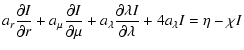
In the following discussion we use the same notation as in
Hauschildt (1992) and reproduce the key equations for convenience. We
use the spherically symmetric form of the special relativistic, time
independent (
![]() ) RTE (hereafter, SSRTE),
the restriction to plane parallel geometry is straightforward. The
calculation of the characteristics is identical that of Hauschildt (1992) and we
thus assume that the characteristics are known. First, we will
describe the process for the formal solution, then we will describe
how we construct the approximate
) RTE (hereafter, SSRTE),
the restriction to plane parallel geometry is straightforward. The
calculation of the characteristics is identical that of Hauschildt (1992) and we
thus assume that the characteristics are known. First, we will
describe the process for the formal solution, then we will describe
how we construct the approximate ![]() operator,
operator, ![]() .
.
In the CMF the SSRTE
in the wavelength (![]() )
scale is given by (Mihalas & Weibel-Mihalas 1984; Hauschildt 1992)
)
scale is given by (Mihalas & Weibel-Mihalas 1984; Hauschildt 1992)
| ar | = | (2) | |
| = | ![$\displaystyle \gamma(1-\mu^2)
\left[{1+\beta\mu\over r}
- \gamma^2\left(\mu+\beta\right){\partial \beta \over \partial r}
\right],$](/articles/aa/full/2004/13/aa0473/img19.gif) |
(3) | |
| = | ![$\displaystyle \gamma
\left[ {\beta(1-\mu^2)\over r}
+\gamma^2\mu\left(\mu+\beta\right){\partial \beta \over \partial r}
\right]\cdot$](/articles/aa/full/2004/13/aa0473/img21.gif) |
(4) |
![\begin{displaymath}a_l = \gamma
\left[ \frac{\beta(1-\mu^2)}{r}
+\gamma^2\mu\left(\mu+\beta\right){\partial \beta \over \partial r}
\right]
\end{displaymath}](/articles/aa/full/2004/13/aa0473/img25.gif)

| |
= | (6) | |
 |
|||
| (7) |
| (9) |
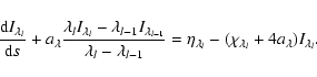
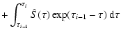
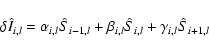
For the tangent rays (for example ray 1 in Fig. 1 of Hauschildt 1992), the formal solution starts at point 2 with I1 given as the outer boundary condition and proceeds along the ray. The formal solution for a core-intersecting ray is split into two parts: (i) integration from point 1 to point N, where I1 is given as the outer boundary condition and (ii) integration from point N+2 to point 2N, where IN+1 is given as the inner boundary condition.
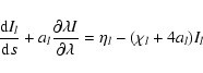
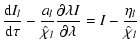
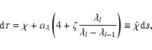
The discretization of the
![]() derivative in
the previous section can be deferred.
We first rewrite Eq. (5) as
derivative in
the previous section can be deferred.
We first rewrite Eq. (5) as

| |
= | (11) | |
| = |  |
(12) |
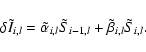
If the velocity field is monotonically increasing
or decreasing we use a stable upwind
discretization of the wavelength derivative. In both cases, the problem
becomes an initial value problem and can be solved for each wavelength once
the results of the previous (smaller or longer) wavelength points are known.
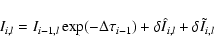
For a monotonically increasing velocity field this gives
| |
= | ![$\displaystyle -\frac{a_{i-1,l}}{\hat\chi_{i-1,l}}
\left[ \frac{\lambda_{l}}{\la...
...1}} I_{i-1,l}- \frac{\lambda_{l-1}}{\lambda_l-\lambda_{l-1}} I_{i-1,l-1}\right]$](/articles/aa/full/2004/13/aa0473/img70.gif) |
(14) |
| = | ![$\displaystyle -\frac{a_{i,l}}{\hat\chi_{i,l}}
\left[ \frac{\lambda_{l}}{\lambda...
...l-1}} I_{i,l}
- \frac{\lambda_{l-1}}{\lambda_l-\lambda_{l-1}} I_{i,l-1}\right].$](/articles/aa/full/2004/13/aa0473/img72.gif) |
(15) |
With these formulae we can write
![]() in the form
in the form
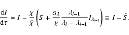
The new form of the formal solution requires only small changes
to the construction of the ![]() operator discussed in
Hauschildt (1992) and Hauschildt et al. (1994).
operator discussed in
Hauschildt (1992) and Hauschildt et al. (1994).
We describe the construction of ![]() for arbitrary bandwidth using
the example of a tangential characteristic. The intersection points
(including the point of tangency) are labeled from left to right, the
direction in which the formal solution proceeds. For convenience, we
label the characteristic tangent to shell k+1 as k. Therefore, the
characteristic k has 2k+1 points of intersection with discrete
shells
for arbitrary bandwidth using
the example of a tangential characteristic. The intersection points
(including the point of tangency) are labeled from left to right, the
direction in which the formal solution proceeds. For convenience, we
label the characteristic tangent to shell k+1 as k. Therefore, the
characteristic k has 2k+1 points of intersection with discrete
shells
![]() .
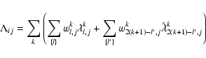
To compute row j of the discrete
.
To compute row j of the discrete
![]() -operator (or
-operator (or ![]() -matrix),
-matrix),
![]() ,
we
sequentially label the intersection points of the characteristic kwith the shell i and define auxiliary quantities
,
we
sequentially label the intersection points of the characteristic kwith the shell i and define auxiliary quantities
![]() and
and
![]() as follows:
as follows:
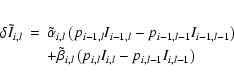
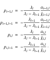
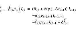
for i<j-1
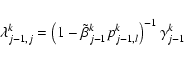
![\begin{eqnarray*}\lambda^k_{j,j} & = & \left(1-\tilde\beta^k_{j} p^k_{j,l}\right...
...{j-1,l}+\exp(-\Delta\tau^k_{j-1})\right]
+ \beta^k_{j} \right)
\end{eqnarray*}](/articles/aa/full/2004/13/aa0473/img85.gif)
![\begin{eqnarray*}\lambda^k_{j+1,j} & = & \left(1-\tilde\beta^k_{j+1}
p^k_{j+1,l...
...^k_{j,l}+\exp(-\Delta\tau^k_{j})\right] + \alpha^k_{j+1}
\right)
\end{eqnarray*}](/articles/aa/full/2004/13/aa0473/img86.gif)
![\begin{eqnarray*}\lambda^k_{i,j} & = & \left(1-\tilde\beta^k_{i}
p^k_{i,l}\right...
...ha^k_{i}
p^k_{i-1,l}+\exp(-\Delta\tau^k_{i-1})\right] \right).
\end{eqnarray*}](/articles/aa/full/2004/13/aa0473/img88.gif)
![\begin{eqnarray*}\hat\lambda^k_{i,j} & = & \left(1-\tilde\beta^k_{i}
p^k_{i,l}\r...
...pha^k_{i}
p^k_{i-1,l}+\exp(-\Delta\tau^k_{i-1})\right] \right)
\end{eqnarray*}](/articles/aa/full/2004/13/aa0473/img90.gif)
![\begin{eqnarray*}\hat\lambda^k_{i,j} & = & \left(1-\tilde\beta^k_{i}
p^k_{i,l}\r...
...ha^k_{i}
p^k_{i-1,l}+\exp(-\Delta\tau^k_{i-1})\right] \right)
\end{eqnarray*}](/articles/aa/full/2004/13/aa0473/img91.gif)
![\begin{eqnarray*}\hat\lambda^k_{i,j} & = & \left(1-\tilde\beta^k_{i}
p^k_{i,l}\r...
...i-1,l}+\exp(-\Delta\tau^k_{i-1}) \right]
+ \alpha^k_i \right)
\end{eqnarray*}](/articles/aa/full/2004/13/aa0473/img92.gif)
![\begin{eqnarray*}\hat\lambda^k_{i,j} & = & \left(1-\tilde\beta^k_{i}
p^k_{i,l}\r...
...{i-1,l}+
\exp(-\Delta\tau^k_{i-1}) \right]
+ \beta_i \right)
\end{eqnarray*}](/articles/aa/full/2004/13/aa0473/img93.gif)
![\begin{eqnarray*}\hat\lambda^k_{i,j} & = & \left(1-\tilde\beta^k_{i}
p^k_{i,l}\r...
...i-1,l}+\exp(-\Delta\tau^k_{i-1}) \right]
+ \gamma^k_i \right)
\end{eqnarray*}](/articles/aa/full/2004/13/aa0473/img94.gif)
![\begin{eqnarray*}\hat\lambda^k_{i,j} & = & \left(1-\tilde\beta^k_{i}
p^k_{i,l}\r...
...ha^k_{i}
p^k_{i-1,l}+\exp(-\Delta\tau^k_{i-1})\right] \right).
\end{eqnarray*}](/articles/aa/full/2004/13/aa0473/img96.gif)
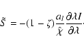
In the second discretization scheme, the wavelength derivative
contains an explicit term, which is required to derive a
recursive method with second order accuracy. We can stabilize the
discretion via a method similar to the standard Crank-Nicholson scheme
(Abramowitz & Stegun 1972).
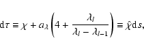
To combine the two discretization schemes described above we introduce a factor
![]() so that for the first scheme in Hauschildt (1992) we
have
so that for the first scheme in Hauschildt (1992) we
have
![]() and for the second discretization we have
and for the second discretization we have
![]() .
With this the optical depth scale along the ray d
.
With this the optical depth scale along the ray d![]() and
and ![]() become
become
It should be expected that the two discretization schemes introduced above
will show different numerical behavior. The ![]() scheme handles the
scheme handles the
![]() and
and
![]() parts differently since the (known)
parts differently since the (known)
![]() is treated like a source term whereas the
is treated like a source term whereas the
![]() term leads to a changed definition of d
term leads to a changed definition of d![]() in the CMF along the ray.
Therefore, the
in the CMF along the ray.
Therefore, the
![]() is basically assumed to vary exponentially
across a characteristic. This will introduce more diffusive behavior
for large optical depths and strong scattering (where the intrinsic assumptions
for
is basically assumed to vary exponentially
across a characteristic. This will introduce more diffusive behavior
for large optical depths and strong scattering (where the intrinsic assumptions
for
![]() and
and
![]() will differ most).
will differ most).
This is not the case for the ![]() discretization which assumes
that the
discretization which assumes
that the
![]() itself can be fitted to
a first order polynomial and treated as a source term. The
discretization step is delayed until the integration of the source
term. Although the discretization is implicit by design, the behavior
of
itself can be fitted to
a first order polynomial and treated as a source term. The
discretization step is delayed until the integration of the source
term. Although the discretization is implicit by design, the behavior
of
![]() is a priori unknown and the second
order nature of the discretization leads to an explicit term. Under
extreme conditions, e.g., a strong line in an optically thin rapidly
expanding gas, it is possible that the numerical integration is
dominated by the "known'' term due to large changes in
is a priori unknown and the second
order nature of the discretization leads to an explicit term. Under
extreme conditions, e.g., a strong line in an optically thin rapidly
expanding gas, it is possible that the numerical integration is
dominated by the "known'' term due to large changes in
![]() .
This leads to numerical instability. We therefore
expect that the two discretizations will show different behavior in
numerical tests.
.
This leads to numerical instability. We therefore
expect that the two discretizations will show different behavior in
numerical tests.
In order to compare and test the two different discretization schemes,
we have devised a simple test model. We consider the case of a 2-level
atom with background continuum on a radial grid (assuming spherical
symmetry). The background continuum is assumed to be grey with
adjustable thermalization fraction
![]() with
with
![]() .
The line of the 2-level atom is
parameterized by its strength relative to the continuum
.
The line of the 2-level atom is
parameterized by its strength relative to the continuum
![]() and its thermalization fraction
and its thermalization fraction
![]() .
For the intrinsic line profile we use a Gaussian
profile with a
.
For the intrinsic line profile we use a Gaussian
profile with a
![]() of
of
![]() .
For the radial
structure, we set
.
For the radial
structure, we set
![]() and use a radial grid with
and use a radial grid with
![]() and
and
![]() (so that the extension of the
test atmosphere is 100) and a logarithmic optical depth grid from
(so that the extension of the
test atmosphere is 100) and a logarithmic optical depth grid from
![]() to 10-6 in the continuum to fix the scale of the
opacities. The velocity law is linear (homologous expansion) with a
prescribed maximum velocity of
to 10-6 in the continuum to fix the scale of the
opacities. The velocity law is linear (homologous expansion) with a
prescribed maximum velocity of
![]() .
The computations are
performed on a wavelength grid that uses a stepsize of 0.1 line width
inside the line and 5 times the line width outside the line if not
specified in detail for some of the test calculations.
.
The computations are
performed on a wavelength grid that uses a stepsize of 0.1 line width
inside the line and 5 times the line width outside the line if not
specified in detail for some of the test calculations.
![\begin{figure}
\par\includegraphics[width=8.8cm,clip]{0473fig1.ps}
\end{figure}](/articles/aa/full/2004/13/aa0473/img126.gif) |
Figure 1:
Absorptive continuum (
|
| Open with DEXTER | |
![\begin{figure}
\par\includegraphics[width=8.8cm,clip]{0473fig2.ps}
\end{figure}](/articles/aa/full/2004/13/aa0473/img127.gif) |
Figure 2:
Scattering dominated continuum
(
|
| Open with DEXTER | |
![\begin{figure}
\par\includegraphics[width=8.8cm,clip]{0473fig3.ps}
\end{figure}](/articles/aa/full/2004/13/aa0473/img128.gif) |
Figure 3:
Absorptive continuum
(
|
| Open with DEXTER | |
![\begin{figure}
\par\includegraphics[width=8.8cm,clip]{0473fig4.ps}
\end{figure}](/articles/aa/full/2004/13/aa0473/img129.gif) |
Figure 4:
Scattering dominated continuum
(
|
| Open with DEXTER | |
The case of a constant step size wavelength grid is shown in
Fig. 5. The step size in wavelength is
![]() .
The
.
The ![]() discretization produces a perfectly flat
continuum after the effect of the (grey) initial condition dies away.
In contrast, the
discretization produces a perfectly flat
continuum after the effect of the (grey) initial condition dies away.
In contrast, the ![]() discretization produces considerable
numerical diffusion in this test, on the average the solution deviates
by more than 10% from the
discretization produces considerable
numerical diffusion in this test, on the average the solution deviates
by more than 10% from the ![]() solution. In addition, the continuum
is not flat but shows a noticeable increase in CMF H (and J)
toward the red.
solution. In addition, the continuum
is not flat but shows a noticeable increase in CMF H (and J)
toward the red.
![\begin{figure}
\par\includegraphics[width=8.8cm,clip]{0473fig5.ps}
\end{figure}](/articles/aa/full/2004/13/aa0473/img130.gif) |
Figure 5:
Scattering dominated continuum
(
|
| Open with DEXTER | |
It is clear that the ![]() discretization gives significantly
better results than the
discretization gives significantly
better results than the ![]() approach for the continuum tests.
approach for the continuum tests.
In contrast to the previous set of tests, we now introduce a strong
line. We set the line strength
![]() with
with
![]() to simulate a strong, scattering dominated line
of a 2-level atom against a background continuum.
Figures 6 and 7 show the results
for absorption and scattering dominated background continua. In both
cases the relative differences in the continua are comparable to the
previous tests. The differences in the lines are actually
comparatively small in both cases, significantly smaller than might be
expected from the continuum test results considering the fact that the
line is strongly scattering dominated. This is most likely caused by
the smoothing effect of the rapidly varying opacity across the line.
The effect of continuum scattering is to considerably widen the
line due to line photons being scattered by the continuum. The more
diffusive
to simulate a strong, scattering dominated line
of a 2-level atom against a background continuum.
Figures 6 and 7 show the results
for absorption and scattering dominated background continua. In both
cases the relative differences in the continua are comparable to the
previous tests. The differences in the lines are actually
comparatively small in both cases, significantly smaller than might be
expected from the continuum test results considering the fact that the
line is strongly scattering dominated. This is most likely caused by
the smoothing effect of the rapidly varying opacity across the line.
The effect of continuum scattering is to considerably widen the
line due to line photons being scattered by the continuum. The more
diffusive ![]() discretization scheme produces an emission feature
that is about 2-3% stronger than the
discretization scheme produces an emission feature
that is about 2-3% stronger than the ![]() discretization
relative to the continuum. It is interesting to note the strong effect
of even a weak (compared to the line itself) background continuum on
the shape of the line and the differences between the two discretizations.
discretization
relative to the continuum. It is interesting to note the strong effect
of even a weak (compared to the line itself) background continuum on
the shape of the line and the differences between the two discretizations.
![\begin{figure}
\par\includegraphics[width=8.8cm,clip]{0473fig6.ps}
\end{figure}](/articles/aa/full/2004/13/aa0473/img133.gif) |
Figure 6:
Strong
|
| Open with DEXTER | |
![\begin{figure}
\par\includegraphics[width=8.5cm,clip]{0473fig7.ps}
\end{figure}](/articles/aa/full/2004/13/aa0473/img134.gif) |
Figure 7:
Strong
|
| Open with DEXTER | |
For the final test we show in Fig. 7 he results of
a calculation for
![]() .
Compared to
.
Compared to ![]() this
calculation shows much smaller differences from the
this
calculation shows much smaller differences from the ![]() case in
the continuum. From the top portion of the figure it is clear that in
the line itself the
case in
the continuum. From the top portion of the figure it is clear that in
the line itself the ![]() model falls roughly half way in
between the
model falls roughly half way in
between the ![]() and
and ![]() cases.
cases.
In all cases the ![]() discretization gives numerically better
results. However, there are situations where the
discretization gives numerically better
results. However, there are situations where the ![]() discretization is numerically unstable, which we discuss in the
following section.
discretization is numerically unstable, which we discuss in the
following section.
In certain conditions, it is possible for the ![]() discretization
to become numerically unstable. This is illustrated in the test case
shown in Fig. 8. The two test lines are in complete LTE (S=B), the background continuum is scattering dominated. The
structure is taken from typical SN Ia structure, but we have
completely ignored the strong line blanketing inherent in SNe Ia by
including line opacity from only Ca II. This procedure is actually
quite useful for line identification in detailed model
calculations. The velocity field is homologous (
discretization
to become numerically unstable. This is illustrated in the test case
shown in Fig. 8. The two test lines are in complete LTE (S=B), the background continuum is scattering dominated. The
structure is taken from typical SN Ia structure, but we have
completely ignored the strong line blanketing inherent in SNe Ia by
including line opacity from only Ca II. This procedure is actually
quite useful for line identification in detailed model
calculations. The velocity field is homologous (
![]() )
with a
maximum speed of
)
with a
maximum speed of
![]() ,
the inner boundary is at
,
the inner boundary is at
![]() .
We use this model rather than the simpler more
academic test cases for two reasons: 1) this is the model where we
actually discovered the instability for
.
We use this model rather than the simpler more
academic test cases for two reasons: 1) this is the model where we
actually discovered the instability for ![]() ,
and 2) we have
been unable to find a simple test case that so strongly reproduces
the instabilities. The continuum is optically thin in absorption
(
,
and 2) we have
been unable to find a simple test case that so strongly reproduces
the instabilities. The continuum is optically thin in absorption
(
![]() )
and reaches a scattering optical
depth
)
and reaches a scattering optical
depth
![]() .
We use a Planck-function as the
inner boundary condition for the intensities for simplicity,
physically it is better to employ a nebular [symmetry] boundary
condition which is shown in Fig. 9. We see that
the instability is evident (for the
.
We use a Planck-function as the
inner boundary condition for the intensities for simplicity,
physically it is better to employ a nebular [symmetry] boundary
condition which is shown in Fig. 9. We see that
the instability is evident (for the ![]() case) even though the
line has gone into emission (note that the different scales
between Figs. 8 and 9 give
the impression that the instability is somewhat suppressed in the
nebular case, but it is simply due to the larger range required to
plot the strong emission features). The unstable wiggles are not
associated with the grid and varying the wavelength resolution does
not significantly affect the output spectrum. While we
believe from our tests that the instability is produced
predominantly in optically thin atmospheres, we have not been able
to ascertain the precise conditions that trigger the instability.
case) even though the
line has gone into emission (note that the different scales
between Figs. 8 and 9 give
the impression that the instability is somewhat suppressed in the
nebular case, but it is simply due to the larger range required to
plot the strong emission features). The unstable wiggles are not
associated with the grid and varying the wavelength resolution does
not significantly affect the output spectrum. While we
believe from our tests that the instability is produced
predominantly in optically thin atmospheres, we have not been able
to ascertain the precise conditions that trigger the instability.
The instability in the ![]() discretization is obvious starting at
the rest wavelength of the line. Even in the line trough the
oscillations created by the instability are apparent. The overall line
shapes are distorted, even in the red emission feature. The
instability vanishes
for
discretization is obvious starting at
the rest wavelength of the line. Even in the line trough the
oscillations created by the instability are apparent. The overall line
shapes are distorted, even in the red emission feature. The
instability vanishes
for
![]() as shown in the Fig. 8. The
differences between the spectra for
as shown in the Fig. 8. The
differences between the spectra for ![]() and 1.0 are very
small, the
and 1.0 are very
small, the ![]() case shows a few percent difference compared
to
case shows a few percent difference compared
to ![]() .
It is clear that the instability of the
.
It is clear that the instability of the ![]() case
can easily be avoided by using
case
can easily be avoided by using ![]() due to the stabilizing
features of the
due to the stabilizing
features of the ![]() discretization. In our test case even
discretization. In our test case even
![]() is sufficient to prevent the instability.
is sufficient to prevent the instability.
![\begin{figure}
\par\includegraphics[angle=90,width=8.5cm,clip]{0473fig8.ps}
\end{figure}](/articles/aa/full/2004/13/aa0473/img143.gif) |
Figure 8:
Example to illustrate the possibility of
numerical instabilities in the |
| Open with DEXTER | |
![\begin{figure}
\par\includegraphics[angle=90,width=8.8cm,clip]{0473fig9.ps}
\end{figure}](/articles/aa/full/2004/13/aa0473/img144.gif) |
Figure 9: The same structure as was used in Fig. 8, but with nebular (symmetry) boundary conditions. |
| Open with DEXTER | |
We have studied the discretization of the
![]() term in the co-moving frame
radiative transfer equation. We have found that we can write a second
order discretization scheme, which is in general more accurate than
our previous method, but
it is possible for this scheme to become unstable. We have constructed a
hybrid Crank-Nicholson
like scheme, which is unconditionally stable. We have been unable to
identify the exact conditions which lead to the unstable behavior, but
we have shown that even with a small admixture of the unconditionally
stable scheme, stability is recovered. We recommend using a small
value of
term in the co-moving frame
radiative transfer equation. We have found that we can write a second
order discretization scheme, which is in general more accurate than
our previous method, but
it is possible for this scheme to become unstable. We have constructed a
hybrid Crank-Nicholson
like scheme, which is unconditionally stable. We have been unable to
identify the exact conditions which lead to the unstable behavior, but
we have shown that even with a small admixture of the unconditionally
stable scheme, stability is recovered. We recommend using a small
value of
![]() ,
which in all our tests leads to recovered
stability and is more accurate than a higher value of
,
which in all our tests leads to recovered
stability and is more accurate than a higher value of ![]() .
However, until we determine the exact conditions that trigger
the instability the cautious user should vary
.
However, until we determine the exact conditions that trigger
the instability the cautious user should vary ![]() and determine
the sensitivity of the results to its value.
and determine
the sensitivity of the results to its value.
Acknowledgements
We thank the referee for a very helpful report which significantly improved the presentation of this paper. This work was supported in part by NASA grants NAG 5-8425 and NAG 5-3619 to the University of Georgia and by NASA grant NAG5-3505, NSF grants AST-0204771 and AST-0307323, and an IBM SUR grant to the University of Oklahoma. PHH was supported in part by the Pôle Scientifique de Modélisation Numérique at ENS-Lyon. Some of the calculations presented here were performed at the San Diego Supercomputer Center (SDSC), supported by the NSF, at the National Energy Research Supercomputer Center (NERSC), supported by the U.S. DOE, and at the Höchstleistungs Rechenzentrum Nord (HLRN). We thank all these institutions for a generous allocation of computer time.