N. L. Martín-Hernández1,![]() - J. M. van der Hulst1 - A. G. G. M. Tielens1,2
- J. M. van der Hulst1 - A. G. G. M. Tielens1,2
1 - Kapteyn Institute, PO Box 800, 9700 AV Groningen, The Netherlands
2 - SRON, National Institute for Space Reasearch, PO Box 800,
9700 AV Groningen, The Netherlands
Received 12 July 2002 / Accepted 19 June 2003
Abstract
We present observations of the 4.8 and 8.6 GHz continuum
emission towards 11 southern H II regions made with the
Australian Telescope Compact Array. The observed objects were selected
from the Infrared Space Observatory (ISO) spectral catalogue of compact
H II regions (Peeters et al. 2002b).
The morphologies observed for practically
all the sources are consistent with them being ionized by a cluster of
stars, rather than by a single star. The linear diameters of the
regions range from 0.03 pc to 3 pc, the electron densities from 300 to
![]()
![]() ,
and the Lyman continuum photon flux from 1047 to 1050 s-1.
We confirm the existence of a relation between the density and size of
H II regions which can be fit by a power law shallower than
that predicted by the classic Strömgren
theory.
The radio observations provide, in addition, information about the
distribution of the ionized gas within the ISO apertures.
As a result of the combined radio and infrared study, estimates of
the extinction in the infrared and the metal
content of the nebular gas were calculated.
In this analysis, we also included several (ultra)compact H II regions
previously observed by the Very Large Array. Values for
extinction in the K-band
between
,
and the Lyman continuum photon flux from 1047 to 1050 s-1.
We confirm the existence of a relation between the density and size of
H II regions which can be fit by a power law shallower than
that predicted by the classic Strömgren
theory.
The radio observations provide, in addition, information about the
distribution of the ionized gas within the ISO apertures.
As a result of the combined radio and infrared study, estimates of
the extinction in the infrared and the metal
content of the nebular gas were calculated.
In this analysis, we also included several (ultra)compact H II regions
previously observed by the Very Large Array. Values for
extinction in the K-band
between ![]() 0 and 6 mag are found. The elemental abundances of
nitrogen, neon, argon and sulphur were found
to decrease with Galactocentric distance. Finally, the degree of
ionization of the nebulae is confirmed to be correlated
with the metal content.
0 and 6 mag are found. The elemental abundances of
nitrogen, neon, argon and sulphur were found
to decrease with Galactocentric distance. Finally, the degree of
ionization of the nebulae is confirmed to be correlated
with the metal content.
Key words: instrumentation: interferometers - ISM: H II regions - radio continuum: ISM - ISM: abundances - ISM: dust, extinction
H II regions are photoionized regions surrounding massive O and early
B stars. When the O and B stars are newly formed, they are still
deeply embedded in their parental molecular cloud and the associated
H II regions are characterized by their small sizes
(diameter ![]() 0.05 pc)
and high densities (
0.05 pc)
and high densities (![]()
![]() 104
104
![]() ). These ultracompact
H II regions evolve further into compact and classical H II regions when the dense,
ionized gas expands into the surrounding molecular gas.
Classical H II regions have diameters
). These ultracompact
H II regions evolve further into compact and classical H II regions when the dense,
ionized gas expands into the surrounding molecular gas.
Classical H II regions have diameters ![]() 0.5 pc and densities
0.5 pc and densities ![]() 103
103
![]() (Garay & Lizano 1999).
Dust in the molecular gas which surrounds the stars
and their H II regions absorbs nearly all the stellar radiation,
either directly or after being processed in the nebula, and re-emit it
in the far-infrared.
Because of the high degree of obscuration due to this surrounding
dust, most H II regions are practically
invisible at optical wavelengths and can
only be studied at infrared and radio wavelengths.
(Garay & Lizano 1999).
Dust in the molecular gas which surrounds the stars
and their H II regions absorbs nearly all the stellar radiation,
either directly or after being processed in the nebula, and re-emit it
in the far-infrared.
Because of the high degree of obscuration due to this surrounding
dust, most H II regions are practically
invisible at optical wavelengths and can
only be studied at infrared and radio wavelengths.
Studies of large samples of ultracompact and compact
H II regions have been made in the infrared using the IRAS LRS data
(e.g. Simpson & Rubin 1990), ground-based observations with low
resolution (e.g. Faison et al. 1998), airborne observations with
the Kuiper Airborne Observatory
(e.g. Rudolph et al. 1997; Simpson et al. 1995; Afflerbach et al. 1997) and more recently,
observations from space made with the Infrared Space Observatory (ISO)
(e.g. Peeters et al. 2002b; Giveon et al. 2002b; Vermeij et al. 2002a).
The ISO observations gave access, for the first time, to the
complete 2.3-196
![]() spectrum and allowed a study of the
ionizing conditions in H II regions and derive their relative and
absolute elemental abundances
(e.g. Giveon et al. 2002b; Vermeij & van der Hulst 2002; Martín-Hernández et al. 2002a),
and catalogue their molecular and dust content
(Boogert 1999; Vermeij et al. 2002b; Peeters et al. 2002a).
spectrum and allowed a study of the
ionizing conditions in H II regions and derive their relative and
absolute elemental abundances
(e.g. Giveon et al. 2002b; Vermeij & van der Hulst 2002; Martín-Hernández et al. 2002a),
and catalogue their molecular and dust content
(Boogert 1999; Vermeij et al. 2002b; Peeters et al. 2002a).
| IRAS coordinates | Restoring beam | |||||||||||||
| IRAS | RA | Dec | 4.8 GHz | 8.6 GHz | 4.8 GHz | 8.6 GHz | ||||||||
name |
(J2000.0) | (J2000.0) | PA ( |
PA ( |
(mJy/beam) | |||||||||
10589-6034 |
11 | 00 | 59.8 | -60 | 50 | 27.1 |
|
-4.2 |
|
31.8 | 0.7 | 0.4 | ||
11143-6113 |
11 | 16 | 33.8 | -61 | 29 | 59.4 |
|
-3.2 |
|
-1.7 | 0.2 | 0.1 | ||
12063-6259 |
12 | 09 | 01.1 | -63 | 15 | 54.7 |
|
-5.2 |
|
-11.8 | 1.5 | 0.7 | ||
12073-6233 |
12 | 10 | 00.3 | -62 | 49 | 56.5 |
|
-3.2 |
|
-5.3 | 3.7 | 2.1 | ||
12331-6134 |
12 | 36 | 01.9 | -61 | 51 | 03.9 |
|
-4.0 |
|
-3.0 | 0.4 | 0.3 | ||
15384-5348 |
15 | 42 | 17.1 | -53 | 58 | 31.5 |
|
-7.7 |
|
-11.0 | 0.3 | 0.2 | ||
15502-5302 |
15 | 54 | 06.0 | -53 | 11 | 36.4 |
|
-21.0 |
|
-32.7 | 2.9 | 1.9 | ||
16128-5109 |
16 | 16 | 39.3 | -51 | 16 | 58.3 |
|
-20.8 |
|
-29.7 | 1.0 | 0.8 | ||
17160-3707 |
17 | 19 | 26.1 | -37 | 10 | 53.8 |
|
-4.0 |
|
-6.0 | 0.5 | 0.5 | ||
17221-3619 |
17 | 25 | 31.7 | -36 | 21 | 53.5 |
|
-6.6 |
|
-9.5 | 0.6 | 0.1 | ||
17279-3350 |
17 | 31 | 18.0 | -33 | 52 | 49.4 |
|
-5.6 |
|
-7.5 | 0.3 | 0.2 | ||
Radio continuum surveys of ultracompact and compact H II regions with high angular resolution have been made with the Very Large Array (VLA) of the National Radio Astronomy Observatory (e.g. Kim & Koo 2001; Kurtz et al. 1999; Rudolph et al. 1996; Wood & Churchwell 1989; Garay et al. 1993; Fich 1993; Afflerbach et al. 1996; Kurtz et al. 1994). These observations have allowed systematic studies of the morphologies and physical conditions of H II regions (e.g. emission measure, physical size and electron density). There is, however, no equivalent radio study at high angular resolution of H II regions in the southern hemisphere. Such a study can be conducted with the Australian Telescope Compact Array (ATCA), located at the Paul Wild Observatory in Narrabri and part of the CSIRO Australia Telescope National Facility.
We have completed a survey of compact H II regions in the southern hemisphere with the ATCA at both 4.8 and 8.6 GHz. Our sample consists of 11 sources selected from the ISO spectral catalogue of compact H II regions (Peeters et al. 2002b). These source were among those located in the South Hemisphere for which radio interferometric observations were not available in the literature. These radio continuum observations provide us with an unobscured view of the morphology of these H II regions and estimates of several properties of the ionized gas such as the emission measure, the physical size and the electron density. Moreover, the radio fluxes can be used to give an indirect measure of the total number of ionizing photons, and hence, provide information on the nature and the number of ionizing stars in the H II regions.
These observations provide, in addition, information about the distribution of the ionized gas within the ISO apertures. This information ensures reliable comparison between the radio and the ISO observations. This multi-wavelength comparison allows us to estimate the extinction by contrasting the H I recombination line fluxes observed by ISO with the thermal radio fluxes, which measure the total ionized mass without any effects from extinction. Moreover, the use of the thermal radio fluxes in combination with the fine-structure lines in the ISO spectra allows us to estimate accurate elemental abundances.
In order to increase the statistical significance of our sample, we have included observations of several northern compact H II regions made by Wood & Churchwell (1989) and Kurtz et al. (1994) with the VLA. These observations are analyzed in the same way as the ATCA sample.
This paper is structured as follows. Section 2 describes the ATCA observations and the data reduction. A comparison with single dish observations is made. Section 3 presents contour maps of the H II regions and discusses the sources individually. The VLA data included in the posterior analysis is also described here. In Sect. 4, estimates of the physical properties of the ionized gas calculated from the thermal radio fluxes are given. Section 5 presents the combined analysis of the ISO and radio continuum observations. This analysis includes estimates of the near- and mid-infrared extinction and the elemental abundances of nitrogen, neon, sulphur and argon. Finally, Sect. 6 discusses and summarizes the results of the paper.
The objects were observed with the ATCA. The ATCA is an East-West synthesis instrument with 5 22-m antennas on a 6 km track. Five antennas are movable into configurations with baselines between 31 m and 6 km. The data were obtained in snapshot mode during two different runs on 8-9 April 2000 and 18-19 May 2000 in the 6 km (6D) and 1.5 km (1.5D) configurations. The sample objects and pointing coordinates are listed in Table 1. Each object was observed 5 times each observing run for 8 min, so for each object we have an effective integration time of 80 min covering 10 different hour angles, separated by about 18 degrees in hour angle.
The ATCA data were calibrated according to standard techniques using
the MIRIAD software package described in The Miriad User's Guide![]() (see also Sault et al. 1995). ATCA calibrator
sources close to the target sources were used to track the gains and
phases of the individual antennas. The flux density scale was
calibrated using observations of the compact extragalactic source PKS 1934-638 (the ATCA primary calibrator), for which values of 5.829 Jy
at 4.8 GHz and 2.842 GHz Jy at 8.6 GHz were adopted for both runs. PKS 1934-638 has no detectable linear polarization and therefore can be
used to solve for polarization leakages.
The images were formed using the technique of multi-frequency synthesis
and uniform weighting with pixel sizes of 0.3
(see also Sault et al. 1995). ATCA calibrator
sources close to the target sources were used to track the gains and
phases of the individual antennas. The flux density scale was
calibrated using observations of the compact extragalactic source PKS 1934-638 (the ATCA primary calibrator), for which values of 5.829 Jy
at 4.8 GHz and 2.842 GHz Jy at 8.6 GHz were adopted for both runs. PKS 1934-638 has no detectable linear polarization and therefore can be
used to solve for polarization leakages.
The images were formed using the technique of multi-frequency synthesis
and uniform weighting with pixel sizes of 0.3
![]() .
These images,
with a typical theoretical rms of
.
These images,
with a typical theoretical rms of ![]() 0.2 mJy beam-1, were
deconvolved using the SDI CLEAN algorithm (Steer et al. 1984)
and restored with the diffraction limited beams. Values for the rms noise
of the final images are summarized in Table 1.
0.2 mJy beam-1, were
deconvolved using the SDI CLEAN algorithm (Steer et al. 1984)
and restored with the diffraction limited beams. Values for the rms noise
of the final images are summarized in Table 1.
Every image was analysed in the following way. The peak flux densities
and coordinates of the different components were determined using the
task maxfit in MIRIAD. The integrated flux densities were
obtained from integrating the images within the 3![]() contour
using the task ellint.
We estimate that the uncertainty in these integrated flux densities is
no larger than 10%.
Finally, the sizes were determined using the task imfit and
fitting an elliptical disk.
Peak coordinates, peak and integrated flux densities, and sizes are
reported in Table 2.
In the case of sources with multiple components, the peak coordinate, peak
flux density, and whenever possible, integrated flux density and size, are
given for every individual component as labelled in Fig. 2.
contour
using the task ellint.
We estimate that the uncertainty in these integrated flux densities is
no larger than 10%.
Finally, the sizes were determined using the task imfit and
fitting an elliptical disk.
Peak coordinates, peak and integrated flux densities, and sizes are
reported in Table 2.
In the case of sources with multiple components, the peak coordinate, peak
flux density, and whenever possible, integrated flux density and size, are
given for every individual component as labelled in Fig. 2.
Interferometric observations are limited to angular scales smaller
than
![]() ,
where d is the shortest baseline (77 m for our observations) and D is the diameter of a single antenna
(22 m for the ATCA). This limits our ATCA data to angular scales
smaller than
,
where d is the shortest baseline (77 m for our observations) and D is the diameter of a single antenna
(22 m for the ATCA). This limits our ATCA data to angular scales
smaller than
![]()
![]() and 2
and 2![]() respectively for
the 4.8 and 8.6 GHz observations. It is quite clear from
Fig. 2 that
most of the 8.6 GHz images of the more extended and complex sources suffer
from this problem.
respectively for
the 4.8 and 8.6 GHz observations. It is quite clear from
Fig. 2 that
most of the 8.6 GHz images of the more extended and complex sources suffer
from this problem.
In addition to the missing short spacing information, these observations are limited by the coarse sampling of the u,v plane. Each observation consists only of 10 cuts in the u,v plane separated by about 18 degrees in hour angle, rather than continuous 12 hour tracks. Complex brightness distributions are therefore difficult to reconstruct reliably, which affects the fidelity of the images. Since we are mainly interested in using this data to get values for the total flux and the flux within ISO aperture size subregions, this limitation is less severe than the lack of very short spacings.
A way to quantify how much extended emission we are missing is by comparing our total flux densities to single dish observations. For this purpose we use the 64-m Parkes Telescope observations by Caswell & Haynes (1987), who quoted 5 GHz flux densities towards all of our sources except IRAS 17160. Figure 1 shows that the ratio between the single dish and our 4.8 GHz ATCA observations is less than a factor of 2 for all the sources except for IRAS 10589, IRAS 15502 and IRAS 17279. We discuss these differences for each source individually in the next section. At 8.6 GHz, the ratio between single-dish and interferometric flux densities is expected to be larger.
| 4.8 GHz | 8.6 GHz | ||||||||||
| Source | Component | Peak coordinatesa | Peakb | Integ. |
Sourced | Comp. | Peak coordinatesa | Peakb | Integ. |
Sourced | |
| (RA, Dec) | size | (RA, Dec) | size | ||||||||
| IRAS 10589 | 11:01:00.16 -60:50:22.4 | 79 | 1218 |
|
11:01:00.20 -60:50:22.2 | 24 | 1343 |
|
|||
| IRAS 11143 | 11:16:32.91 -61:30:12.7 | 6 | 2733 |
|
|||||||
| IRAS 12063 | 1961 |
|
1400 | ||||||||
| ... | A | 12:09:01.12 -63:15:52.9 | 158 | A | 12:09:01.04 -63:15:52.9 | 63 | |||||
| ... | B | 12:09:01.01 -63:16:00.8 | 106 | B1
|
12:09:00.99 -63:15:59.3 | 41 | |||||
| B2
|
12:09:01.17 -63:16:02.2 | 37 | |||||||||
| IRAS 12073 | 15 377 |
12 853 |
|||||||||
| ... | A | 12:10:01.11 -62:49:53.9 | 383 | 4955 | A | 12:10:01.06 -62:49:53.6 | 184 | 4098 | 5.8 | ||
| ... | B | 12:09:57.88 -62:49:33.5 | 141 | 1145 | B | 12:09:58.10 -62:49:32.8 | 57 | 656 |
|
||
| IRAS 12331 | 12:36:01.23 -61:51:18.8 | 15 | 3528 |
|
12:36:01.28 -61:51:17.7 | 4 | 2699 |
|
|||
| IRAS 15384 | 15:42:16.86 -53:58:33.4 | 59 | 4753 |
|
15:42:16.87 -53:58:33.8 | 16 | 3505 |
|
|||
| IRAS 15502 | 2172 | 3202 | |||||||||
| ... | A | 15:54:06.40 -53:11:40.2 | 555 | 1853 | 4.7 | A | 15:54:06.43 -53:11:40.6 | 543 | 3013 | 3.6 | |
| ... | B | 15:54:05.26 -53:11:39.4 | 90 | 234 | 2.5 | B | |||||
| IRAS 16128 | 9266 |
|
5795 |
|
|||||||
| ... | A | 16:16:41.06 -51:17:02.0 | 182 | A | 16:16:41.06 -51:17:02.1 | 65 | |||||
| ... | B | 16:16:40.55 -51:17:08.5 | 161 | B | 16:16:40.78 -51:17:09.2 | 45 | |||||
| ... | C | 16:16:40.32 -51:17:13.1 | 155 | C | 16:16:40.44 -51:17:08.2 | 55 | |||||
| ... | D | 16:16:40.25 -51:17:13.1 | 164 | D | 16:16:40.23 -51:17:13.0 | 74 | |||||
| IRAS 17160 | 5475 |
||||||||||
| ... | A | 17:19:27.51 -37:11:02.7 | 123 | 1230 |
13 |
A | 17:19:27.48 -37:11:04.6 | 41 | 2365 |
|
|
| ... | B | 17:19:26.92 -37:10:24.6 | 49 | 110 | 4.4 | B | 17:19:27.01 -37:10:25.2 | 14 | 67 | 3.2 | |
| ... | C | 17:19:32.74 -37:10:46.8 | 53 | 200 | C | 17:19:32.76 -37:10:47.4 | 18 | 54 | 2.7 | ||
| ... | D | 17:19:35.69 -37:10:56.5 | 142 | 213 | 3.1 | D | 17:19:35.68 -37:10:56.4 | 81 | 223 | 2.2 | |
| ... | E | 17:19:25.55 -37:10:04.6 | 4 | 5 | <2.3 | E | 17:19:25.60 -37:10:04.9 | 38 | 39 | <1.1 | |
| IRAS 17221 | 17:25:31.05 -36:21:51.9 | 19 | 2905 | 67 | 17:25:31.01 -36:21:52.1 | 5 | 1479 | 44 | |||
| IRAS 17279 | 1532 |
||||||||||
| ... | A | 17:31:17.62 -33:52:45.4 | 24 |
|
A | 17:31:17.63 -33:52:45.1 | 10 | 517 | 20 |
||
| ... | B | 17:31:20.54 -33:53:25.7 | 95 | 103 | 2.7 | B | 17:31:20.54 -33:53:25.7 | 46 | 62 | 1.9 | |
| ... | C | 17:31:15.04 -33:51:16.0 | 85 | 124 | 3.4 | C | 17:31:15.03 -33:51:15.8 | 47 | 113 | 2.0 | |
|
a Coordinates in right ascension and declination (J2000.0); the
units of right ascension are hours, minutes and seconds; the units of
declination are degrees, arcmin and arcsec.
b Peak flux density in mJy beam-1. c Total integrated flux density in mJy. d Source size in arcsec. |
Contour maps of the radio continuum emission at 4.8 GHz and 8.6 GHz
of the 11 IRAS sources observed are shown in
Fig. 2. The smoother
appearance of the 4.8 GHz maps is due to the lower angular resolution
(approximately half the angular resolution of the higher frequency
observations). The contour levels are specified in the figure
caption. Overplotted on the 4.8 GHz maps we also show the 4 nominal apertures
of the ISO Short Wavelength Spectrometer (SWS):
![]() ,
,
![]() ,
,
![]() and
and
![]() .
.
![\begin{figure}
\par\includegraphics[width=8.5cm,clip]{H3840F1.EPS}
\end{figure}](/articles/aa/full/2003/33/aah3840/img108.gif) |
Figure 1: Comparison between the total 6 cm flux densities measured from the ATCA and the single dish observations made with the Parkes Telescope (Caswell & Haynes 1987). A 10% uncertainty is considered for both ATCA and Parkes flux densities. |
A puzzling linear feature is seen on the western side of
IRAS 15384-5348. This feature is oriented East-West and is
approximately 55
![]() in length and 15
in length and 15
![]() in width.
The feature is only observed at 4.8 GHz (cf.
Fig. 2f).
Since this feature is not detected in our 8.6 GHz image one would tend
to conclude its emission is non-thermal with a very steep spectral
index. On the other hand, the faint emission at the eastern side of the
H II region, which is at about the same level of brightness, is not
seen either in the 8.6 GHz image. This suggests that the factor 1.6 difference in the length of the shortest spacing, coupled to the extent
of the emission in this H II region, severely hampers a direct comparison.
It certainly makes a direct estimate of the spectral index of the
extended emission impossible.
We conducted a test to check whether the short spacing problem is causing
the dissappearance of the linear feature at 8.6 GHz.
We created a 4.8 GHz image with the same spacings as the 8.6 GHz image
by eliminating all spacings shorter than the
equivalent shortest spacing (in
in width.
The feature is only observed at 4.8 GHz (cf.
Fig. 2f).
Since this feature is not detected in our 8.6 GHz image one would tend
to conclude its emission is non-thermal with a very steep spectral
index. On the other hand, the faint emission at the eastern side of the
H II region, which is at about the same level of brightness, is not
seen either in the 8.6 GHz image. This suggests that the factor 1.6 difference in the length of the shortest spacing, coupled to the extent
of the emission in this H II region, severely hampers a direct comparison.
It certainly makes a direct estimate of the spectral index of the
extended emission impossible.
We conducted a test to check whether the short spacing problem is causing
the dissappearance of the linear feature at 8.6 GHz.
We created a 4.8 GHz image with the same spacings as the 8.6 GHz image
by eliminating all spacings shorter than the
equivalent shortest spacing (in ![]() )
at 8.6 GHz.
In the new 4.8 GHz image, only the compact core of the H II region
is present. This indicates that the absence of the filament in the
8.6 GHz image is indeed a short spacing problem.
)
at 8.6 GHz.
In the new 4.8 GHz image, only the compact core of the H II region
is present. This indicates that the absence of the filament in the
8.6 GHz image is indeed a short spacing problem.
Figure 3 (left) shows the 4.8 GHz continuum
contours overlaid on the SSS I-band image. Five
radio knots
can be distinguished along the filament which we will label 1 to 5
from East to West respectively. Knot 3 is the brightest one, with a
peak flux density of 5.4 mJy beam-1. The knot structure is highly
symmetric with respect to knot 3. Knots 2 and 4 are separated from
knot 3 by 8.6
![]() ;
knots 1 and 5, on the other hand, are also
symmetrically located from knot 3 (19.7
;
knots 1 and 5, on the other hand, are also
symmetrically located from knot 3 (19.7
![]() ). As well, the peak
flux densities of knots 2 and 4 agree (4.4 mJy beam-1). Knots 1 and 5 are weaker (2.7 and 3.6 mJy beam-1). This suggests the possibility
that we have detected an extragalactic radio source,
though the filament does not
really resemble the classic double radio lobe structure.
). As well, the peak
flux densities of knots 2 and 4 agree (4.4 mJy beam-1). Knots 1 and 5 are weaker (2.7 and 3.6 mJy beam-1). This suggests the possibility
that we have detected an extragalactic radio source,
though the filament does not
really resemble the classic double radio lobe structure.
On the SSS, only two faint stars (![]() mag) are coincident with the
radio feature. They are located, however,
at 4.6
mag) are coincident with the
radio feature. They are located, however,
at 4.6
![]() to the North-West and 7.0
to the North-West and 7.0
![]() to the South-West of
knot 3 and
it is therefore unlikely that they are directly connected to the radio knot.
The lack of a clear optical counterpart is, on the other hand, not surprising
because of the large extinction in this direction. The H II region
IRAS 15384-5348, for instance, suffers a visible extinction of
to the South-West of
knot 3 and
it is therefore unlikely that they are directly connected to the radio knot.
The lack of a clear optical counterpart is, on the other hand, not surprising
because of the large extinction in this direction. The H II region
IRAS 15384-5348, for instance, suffers a visible extinction of ![]() 14 mag (Sect. 5.1).
14 mag (Sect. 5.1).
We also looked at images in the mid-infrared. Here we find a striking
resemblance.
Figure 3 (right) shows the 4![]() field of view around the objects observed by the MSX satellite at 8.3
field of view around the objects observed by the MSX satellite at 8.3
![]() .
Overlaid on the MSX image are the contours of the 4.8 GHz continuum smoothed to a resolution of 20
.
Overlaid on the MSX image are the contours of the 4.8 GHz continuum smoothed to a resolution of 20
![]() ,
equivalent to that of the MSX. While the radio continuum image delineates
the ionized gas (and possibly non-thermal emission), the 8.3
,
equivalent to that of the MSX. While the radio continuum image delineates
the ionized gas (and possibly non-thermal emission), the 8.3
![]() image
includes the dominant
PAH molecular emission at 6.2, 7.7 and 8.7
image
includes the dominant
PAH molecular emission at 6.2, 7.7 and 8.7
![]() ,
which is particularly
strong in the neutral zone (PDR) surrounding the ionized gas.
The mid-infrared image is rather
complex, with extensions at both the eastern and western sides of the
H II region.
The large
extension to the western side appears to coincide with the radio
feature. Since radio galaxies seldom show bright infrared
emission associated with their radio lobes, this points
towards a Galactic origin for the filament,
and perhaps this structure represents an embedded protostar with an
associated jet.
,
which is particularly
strong in the neutral zone (PDR) surrounding the ionized gas.
The mid-infrared image is rather
complex, with extensions at both the eastern and western sides of the
H II region.
The large
extension to the western side appears to coincide with the radio
feature. Since radio galaxies seldom show bright infrared
emission associated with their radio lobes, this points
towards a Galactic origin for the filament,
and perhaps this structure represents an embedded protostar with an
associated jet.
| Source | Integ. |
Size | ||
| (GHz) | (mJy/beam) | (Jy) | (
|
|
| IRAS 01045+6505 | 8.4 | 0.29 | 242 | 4.7 |
| IRAS 18032-2032 | 8.4 | 1.24 | 461, 71, 66 |
|
| IRAS 18479-0005 | 8.4 | 1.30 | 2588 |
|
| IRAS 19442+2427 | 8.4 | 0.19 | 80 |
|
| IRAS 19598+3324 | 8.4 | 2.57 | 3380 | 6 |
| DR21 | 8.4 | 2.75 | 561, 864 |
|
| IRAS 23133+6050 | 8.4 | 0.74 | 737 | 9 |
|
|
Similar high-resolution radio continuum observations of "northern'' ultracompact H II regions have been made using the VLA of the National Radio Astronomy Observatory. 15 sources out of our ISO sample (Peeters et al. 2002b) had been observed in the surveys by Wood & Churchwell (1989) and Kurtz et al. (1994) at either 4.9 or 8.4 GHz. The images resulting from these observations were kindly provided to us by Ed Churchwell.
Eight out of these 15 sources were disregarded for various reasons:
(i) no strong infrared lines have been detected with ISO (IRAS 02575+6017 and IRAS 18162-2048);
(ii) the ISO-SWS apertures completely missed the H II region as
outlined by the radio continuum emission (IRAS 21306+5540);
(iii) the Br![]() line flux predicted using the integrated radio flux
density in the SWS aperture where this line is observed is
smaller than the observed line flux by ISO-SWS (IRAS 18434-0242,
IRAS 18469-0132, IRAS 18502+0051, IRAS 22308+5812
and IRAS 23030+5958).
line flux predicted using the integrated radio flux
density in the SWS aperture where this line is observed is
smaller than the observed line flux by ISO-SWS (IRAS 18434-0242,
IRAS 18469-0132, IRAS 18502+0051, IRAS 22308+5812
and IRAS 23030+5958).
The remaining seven sources are listed in Table 3, where the wavelength of the observation, the rms noise, the total integrated flux density and the size are given. Contour maps with the 4 nominal ISO-SWS apertures are presented in Fig. 4. The Galactocentric and heliocentric distances to these sources (Peeters et al. 2002b) are listed in Cols. 2 and 3 of Table 4.
It is clear from our continuum images that many sources have complex structures. Complicated geometries hamper the determination of important physical parameters such as opacity, electron density and emission measure because the geometry of the source is required. The simplest geometry one can consider is a spherical, homogeneous H II region. In view of the radio contour maps, most of the sources are not spheres. However, we can estimate approximate physical properties by considering the objects to be spheres with a total flux density and diameter equal to the ones reported in Table 2. This approximation is appropiate for the quasi-spherical and point sources such as IRAS 12073 A, IRAS 15502 A and B, IRAS 17160 B, D and E or IRAS 17279 B and C. In the case of the other, more complex sources, the geometrical average of the major and minor axes can be taken as a representative size. The cases of IRAS 16128, IRAS 17160 A and IRAS 17279 A are more complicated. They are, however, better resolved by the 8.6 GHz observations, and the corresponding flux densities and sizes are used instead to characterize the physical properties of the compact cores.
Another crucial factor in the determination of physical parameters, such as the physical diameter of the source and the Lyman continuum photon flux, is the distance to the object. Kinematic distances to the H II regions have been presented in Peeters et al. (2002b). The Galactic and heliocentric distances towards the objects are given in Cols. 2 and 3 of Table 4. In the cases of IRAS 16128, IRAS 17160, IRAS 17221 and IRAS 17279, for which the heliocentric ambiguity has not been resolved, both the near and far distances are quoted. For these objects, two different linear sizes, electron densities and Lyman continuum fluxes result because of this ambiguity in the distance. However, for the discussion in this paper we will only consider the near distance.
Considering an ionized, optically thin gas with an electron
temperature ![]() ,
the
optical depth,
,
the
optical depth, ![]() ,
is defined by:
,
is defined by:
| (1) |
![\begin{displaymath}{T_{\rm b}}(\nu)= 1.1\times10^{-15}{ {S_\nu} \over {\nu_{\rm ~GHz}^2
\Omega}}~[{\rm K}],
\end{displaymath}](/articles/aa/full/2003/33/aah3840/img134.gif) |
(2) |
![\begin{displaymath}{EM}= 12.143~{ {\tau_\nu} \over
{ a_\nu T_{\rm e}^{-1.35} \nu_{\rm ~GHz}^{-2.1}} }~[{\rm ~pc~cm^{-6}}],
\end{displaymath}](/articles/aa/full/2003/33/aah3840/img136.gif) |
(3) |
Following the formalism explained by Wood & Churchwell (1989), the rms electron
density can be derived from:
![\begin{displaymath}{n_{\rm e}}= 1.4\times 10^3
\sqrt { \left ( { {EM} \over {10...
...t ( { {0.5 {\rm ~pc}} \over {D} } \right ) } ~[{\rm cm^{-3}}],
\end{displaymath}](/articles/aa/full/2003/33/aah3840/img138.gif) |
(4) |
![\begin{displaymath}N_{\rm Lyc} = 4.634\times10^{46}
\left( {T_{\rm e} \over {10...
...nu} \over {\rm 1~Jy}} \right )
a_{\nu}^{-1}
~[{\rm s^{-1}}],
\end{displaymath}](/articles/aa/full/2003/33/aah3840/img140.gif) |
(5) |
The derived physical parameters (diameter, opacity, emission measure,
electron density and photon flux of the Lyman continuum) are shown in
Table 4. They have been computed for
![]() = 7500 K.
= 7500 K.
Ultracompact H II (UCH II) regions
are characterized by their small sizes (diameter ![]() 0.05 pc)
and high densities (
0.05 pc)
and high densities (![]()
![]() 104
104
![]() ), while classical
H II regions have diameters
), while classical
H II regions have diameters ![]() 0.5 pc and
densities
0.5 pc and
densities ![]() 103
103
![]() (Garay & Lizano 1999). The
characteristics of compact H II (CH II) regions are in between those of the
ultracompact and classic ones. Among the total of 19 individual
objects observed by the ATCA, only IRAS 17160 E can be classified as
an UCH II region; from the rest, approximately 13 can be defined as
CH II regions and 5 (IRAS 11143, IRAS 12063, IRAS 12331, IRAS 17160 A and IRAS 17221) as classical H II regions.
(Garay & Lizano 1999). The
characteristics of compact H II (CH II) regions are in between those of the
ultracompact and classic ones. Among the total of 19 individual
objects observed by the ATCA, only IRAS 17160 E can be classified as
an UCH II region; from the rest, approximately 13 can be defined as
CH II regions and 5 (IRAS 11143, IRAS 12063, IRAS 12331, IRAS 17160 A and IRAS 17221) as classical H II regions.
| Radio properties | |||||||||||
| Source |
|
R | Diameter |
EM | log
|
|
|||||
| (kpc) | (kpc) | (GHz) | (pc) | (106 pc cm-6) | (103
|
(s-1) | (104) | ||||
| IRAS 01045 | 13.8 | 7.0 | 8.4 | 0.16 | 0.03 | 5.2 | 5.7 | 47.82 | 4.10 | ||
| IRAS 10589 | 9.5 | 8.0 | 4.8 | 0.50 | 0.06 | 3.2 | 2.5 | 48.62 | 29.4 | ||
| IRAS 11143 | 9.7 | 8.8 | 4.8 | 2.82 | 0.005 | 0.3 | 0.3 | 49.05 | 17.1 | ||
| IRAS 12063 | 9.3 | 9.5 | 4.8 | 1.22 | 0.02 | 1.2 | 1.0 | 48.97 | 45.0 | ||
| IRAS 12073 | A | 10.1 | 10.8 | 4.8 | 0.41 | 0.6 | 35.5 | 9.3 | 49.49
|
400 | |
| ... | B | ... | ... | ... | 0.37 | 0.2 | 10.1 | 5.2 | 48.85 | ... | |
| IRAS 12331 | 6.9 | 4.5 | 4.8 | 1.47 | 0.006 | 0.3 | 0.5 | 48.58 | 8.45 | ||
| IRAS 15384 | 6.4 | 2.7 | 4.8 | 0.53 | 0.02 | 1.3 | 1.6 | 48.26 | 10.1 | ||
| IRAS 15502 | A | 4.5 | 7.0 | 4.8 | 0.16 | 0.7 | 37.5 | 15.3 | 48.68 |
131 | |
| ... | B | ... | ... | ... | 0.08 | 0.3 | 16.7 | 14.0 | 47.78 | ... | |
| IRAS 16128 | 5.5 | 3.7/11.4 | 8.6 | 0.32/0.98 | 0.05 | 8.8 | 5.2/3.0 | 48.65/49.63 |
22.8/216 | ||
| IRAS 17160 | A | 3.0 | 5.7/11.0 | 8.6 | 0.62/1.20 | 0.01 | 2.2 | 1.9/1.3 | 48.63/49.21 |
35.6/133 | |
| ... | B | ... | ... | 0.09/0.17 | 0.02 | 3.1 | 5.9/4.3 | 47.09/47.66 | ... | ||
| ... | C | ... | ... | 0.07/0.14 | 0.02 | 3.5 | 6.9/4.9 | 47.00/47.56 | ... | ||
| ... | D | ... | ... | 0.06/0.12 | 0.1 | 21.8 | 18.9/13.6 | 47.61/48.18 | ... | ||
| ... | E | ... | ... | 0.03/0.06 | 0.08 | 15.3 | 22.4/16.1 | 46.85/47.42 | ... | ||
| IRAS 17221 | 5.2 | 3.4/13.4 | 4.8 | 1.10/4.35 | 0.005 | 0.3 | 0.5/0.3 | 48.25/49.44 | 7.52/117 | ||
| IRAS 17279 | A | 3.4 | 5.1/11.8 | 8.6 | 0.49/1.14 | 0.003 | 0.6 | 1.1/0.7 | 47.88/48.61 |
10.4/55.9 | |
| ... | B | ... | 4.8 | 0.07/0.15 | 0.1 | 6.3 | 9.7/6.4 | 47.15/47.88 | ... | ||
| ... | C | ... | ... | 0.08/0.19 | 0.09 | 4.8 | 7.6/5.0 | 47.23/47.96 | ... | ||
| IRAS 18032 | B | 3.0 | 5.7 | 8.4 | 0.38 | 0.006 | 1.1 | 1.7 | 47.92 |
32.3 | |
| ... | C | ... | ... | ... | 0.11 | 0.01 | 2.1 | 4.3 | 47.11 | ... | |
| ... | D | ... | ... | ... | 0.03 | 0.2 | 31.2 | 33.6 | 47.08 | ... | |
| IRAS 18479 | A | 7.4 | 13.0 | 8.4 | 0.30 | 0.1 | 27.0 | 9.4 | 49.10 |
147 | |
| ... | B | ... | ... | ... | 0.09 | 0.6 | 119.9 | 35.5 | 48.74 | ... | |
| IRAS 19442 | core | 7.7 | 2.0 | 8.4 | 0.01 | 0.08 | 14.6 | 34.8 | 46.45 |
3.39 | |
| ... | halo | ... | ... | ... | 0.11 | 0.002 | 0.3 | 1.6 | ... | ... | |
| IRAS 19598 | 9.6 | 8.2 | 8.4 | 0.25 | 0.3 | 44.3 | 13.4 | 49.14 | 187 | ||
| DR21 | A | 8.6 | 2.8 | 8.4 | 0.05 | 0.1 | 20.5 | 20.4 | 47.39 | c | |
| ... | B | ... | ... | ... | 0.06 | 0.1 | 21.1 | 18.8 | 47.58 | ... | |
| IRAS 23133 | 12.6 | 6.7 | 8.4 | 0.2 | 0.02 | 4.3 | 4.2 | 48.10 | 27.5 | ||
|
|
Wood & Churchwell (1989) identified five morphological classes of UCH II and
CH II regions based on the appearange of their radio continuum
emission distributions with a spatial resolution of 0.4
![]() :
cometary, core-halo, shell, irregular or multiple peaked and spherical
or unresolved. From the ATCA sample, we can indentified 3 cometary
sources (IRAS 10589, IRAS 15384 and IRAS 17160 C) and 2 core-halo
sources (IRAS 12073 A and IRAS 15502 A). Six are spherical or unresolved
(IRAS 15502 B, IRAS 17160 B-D-E and IRAS 17279 C-B). The rest are
complex sources with multiple embedded components.
:
cometary, core-halo, shell, irregular or multiple peaked and spherical
or unresolved. From the ATCA sample, we can indentified 3 cometary
sources (IRAS 10589, IRAS 15384 and IRAS 17160 C) and 2 core-halo
sources (IRAS 12073 A and IRAS 15502 A). Six are spherical or unresolved
(IRAS 15502 B, IRAS 17160 B-D-E and IRAS 17279 C-B). The rest are
complex sources with multiple embedded components.
The left panel in
Fig. 5 shows a plot of the electron density against
the diameter for all the sources listed in
Table 4. The objects observed by the ATCA are plotted
as filled circles, and those observed by the VLA as open circles. There is
a clear correlation between these two physical parameters. A least
squares fit to the trend gives a slope of
![]() and an
intercept of
and an
intercept of
![]() .
These fit parameters are in excellent
agreement with those derived by Garay et al. (1993) for a large sample of H II regions observed by the VLA.
The dotted curves in the figure
corresponds to lines of constant number of ionizing photons (
1047,
1048.5 and 1050 photons s-1) when the
ionized nebula is described by a Strömgren sphere.
The trend slope observed by the data is clearly shallower.
Following the discussion by Garay & Lizano (1999), we also plot the rate of
Lyman ionizing photons (
.
These fit parameters are in excellent
agreement with those derived by Garay et al. (1993) for a large sample of H II regions observed by the VLA.
The dotted curves in the figure
corresponds to lines of constant number of ionizing photons (
1047,
1048.5 and 1050 photons s-1) when the
ionized nebula is described by a Strömgren sphere.
The trend slope observed by the data is clearly shallower.
Following the discussion by Garay & Lizano (1999), we also plot the rate of
Lyman ionizing photons (
![]() )
against the diameter,
shown in
Fig. 5 (right panel).
The dotted lines correspond to the cases of Strömgren spheres
with
)
against the diameter,
shown in
Fig. 5 (right panel).
The dotted lines correspond to the cases of Strömgren spheres
with ![]() =102.5 and 104.5
=102.5 and 104.5
![]() .
At first sight, and as it has been
stated by Garay et al. (1993) and Garay & Lizano (1999), both figures
seem to indicate that, on
average, ultracompact H II regions are ionized by stars with lower
number of ionizing photons (i.e. by later type stars)
than those ionizing compact and classic
H II regions.
This is not the only possible explanation.
Several other effects can cause the
.
At first sight, and as it has been
stated by Garay et al. (1993) and Garay & Lizano (1999), both figures
seem to indicate that, on
average, ultracompact H II regions are ionized by stars with lower
number of ionizing photons (i.e. by later type stars)
than those ionizing compact and classic
H II regions.
This is not the only possible explanation.
Several other effects can cause the ![]() -D relation to be shallower than predicted
for a pure hydrogen Strömgren sphere. These are:
-D relation to be shallower than predicted
for a pure hydrogen Strömgren sphere. These are:
Within this interpretation, the shallow slope of the ![]() -D relation
is due to the effect of dust.
Since only a few points are expected to have
-D relation
is due to the effect of dust.
Since only a few points are expected to have
![]() photons s-1, the case of a dusty H II region with
photons s-1, the case of a dusty H II region with
![]() photons s-1 represents almost an upper limit to
photons s-1 represents almost an upper limit to ![]() for a given D. The dust abundance must be
highly variable then, since there are some high density nebulae
(clustered around
for a given D. The dust abundance must be
highly variable then, since there are some high density nebulae
(clustered around ![]() =104
=104
![]() and
D=10-0.5 pc) close to
the dust-free Strömgren sphere solution for
and
D=10-0.5 pc) close to
the dust-free Strömgren sphere solution for
![]() 1050 photons s-1. This is close to the upper limit for O stars and hence they
must represent regions with little dust.
1050 photons s-1. This is close to the upper limit for O stars and hence they
must represent regions with little dust.
The abundance of dust in H II regions has been a topic of much controversy. Earlier estimates (Tielens & de Jong 1979; Natta & Panagia 1976), based upon fitting the spectral energy distribution, lead to controversial results mainly reflecting the lack of spatial resolution at far-IR wavelengths. More recent studies (Churchwell et al. 1990; Chini et al. 1986), based upon studies of specific compact H II regions, suggest somewhat depleted dust abundances in the ionized gas. But the inherent uncertainty in the stellar parameters preclude strong conclusions. Theoretically, dust could be sputtered in the hot ionized gas (e.g. Draine & Salpeter 1979) as well as blown out by radiation pressure, and the dust abundance might well be time dependent.
![\begin{figure}
\par\includegraphics[width=7cm,clip]{H3840F6.EPS}
\end{figure}](/articles/aa/full/2003/33/aah3840/img155.gif) |
Figure 6: Plot of the total stellar luminosity against the rate of Lyman ionizing photons. The ATCA sample is represented by filled circles and the VLA sample by open circles. The lines represent the behaviour of a single embedded main sequence (solid), class III (dotted) and class I (dashed) late B/O star. These lines are based on the calibration of early type stars made by Vacca et al. (1996). |
There are thus many factors that may influence the relationship
between the density and diameter of H II regions (or equivalently,
the relationship between
![]() and the diameter). However, it is
difficult to discriminate among these possible factors on the basis of
the present data.
and the diameter). However, it is
difficult to discriminate among these possible factors on the basis of
the present data.
The comparison of the stellar luminosity and Lyman continuum
photon flux is shown in
Fig. 6. The curves represent the behaviour of
a single embedded main sequence, class III and class I late-B/O star
based on the calibration by Vacca et al. (1996). In general, the
observed values of
![]() and L are in
the range of those predicted to be typical of ealy B and O stars. However, a large fraction of the sources lie above the
theoretical predictions for single stars, indicating that a single star
cannot account by itself for all the integrated stellar luminosity. Radio
morphologies of many of the sources show indeed multiple
components.
We note, however, that the IRAS beam is large (
and L are in
the range of those predicted to be typical of ealy B and O stars. However, a large fraction of the sources lie above the
theoretical predictions for single stars, indicating that a single star
cannot account by itself for all the integrated stellar luminosity. Radio
morphologies of many of the sources show indeed multiple
components.
We note, however, that the IRAS beam is large (![]() 1.5
1.5![]() )
and may include
more sources than the radio components observed.
Also, the derived
)
and may include
more sources than the radio components observed.
Also, the derived
![]() values
must be taken as a lower limit if part of the radio flux is
missing from our interferometric observations.
The combined effect of these two facts
would shift points in Fig. 6 down and to the right, thus
improving the correlation.
values
must be taken as a lower limit if part of the radio flux is
missing from our interferometric observations.
The combined effect of these two facts
would shift points in Fig. 6 down and to the right, thus
improving the correlation.
The comparison of the radio continuum observations with the ISO spectroscopic data allows us to further characterize the physical properties
of the
H II regions. In particular, it allows us to study the extinction in
the infrared towards the nebulae, determine elemental abundances
of elements such as nitrogen, neon, sulphur and argon, and constrain the
properties of the ionizing stars.
This comparison, however, requires a detailed analysis of the radio
continuum images in order to determine the total radio flux density
associated with the region observed by every Short Wavelength (2.3-45
![]() ,
SWS) and Long Wavelength (43-196
,
SWS) and Long Wavelength (43-196
![]() ,
LWS) Spectrometer
aperture (see Peeters et al.
2002b for a full description of
the ISO instrument).
,
LWS) Spectrometer
aperture (see Peeters et al.
2002b for a full description of
the ISO instrument).
The characterization of the SWS beam profiles is described in Salama (2000). Basically, each SWS beam profile results from the convolution of the telescope point spread function with the entrance slit, and then with the detector response profile. A different beam profile exists, therefore, for every detector (12 in total). Because of imaging defects inside the instrument, these beam profiles were found to significantly deviate from the predicted shapes. Large differences between the beam profiles are seen along the cross-dispersion direction (cf. Fig. 7): the shapes of the band 1 and band 2 profiles are triangular; the band 3 profiles, although closer to top-hat profiles, are off-center; the band 4 profile resembles a broad, off-center Gaussian. The shapes of the beam profiles have been modeled and included as standalone calibration files (cal36) in the pipeline version 10. Using these files, an appropriate mask has been created for every source and detector at the correct orientation and center position. Afterwards, the original radio maps have been multiplied by these masks and a integrated flux density derived. In the case of the ATCA data, we use the 4.8 GHz maps because of their higher sensitivity to large scale structure. The integrated flux densities which resulted from this analysis are presented in Table 5. The variations in these resulting flux densities depend on the source morphology and orientation of the SWS beams. The bottom right panel in Fig. 7 shows how the flux densities for two extreme cases (IRAS 10589 and IRAS 16128) vary with the SWS band. While the integrated flux densities derived for IRAS 10589 are practically constant, in the case of IRAS 16128, the radio flux integrated over the SWS band 4 aperture is 5 times larger than the one integrated over the SWS band 1A. This happens because IRAS 16128 is much larger than the SWS beams and it is not centered within the apertures.
The LWS beam profile has been recently described by Lloyd (2001). The
size of the aperture, initially assumed to be circular with a diameter
of 100
![]() ,
has been found to be significantly smaller for reasons
which are not entirely known. The best value for most of the detectors
is close to 80
,
has been found to be significantly smaller for reasons
which are not entirely known. The best value for most of the detectors
is close to 80
![]() ;
somewhat smaller for the long wavelength
detectors. Furthermore, the beam profile is also slightly asymmetric
because of instrumental effects. The observed profiles for the short
wavelength detectors are close to a top-hat profile, while they become
more Gaussian towards longer wavelengths. We computed two different masks:
one being a Gaussian with a 80
;
somewhat smaller for the long wavelength
detectors. Furthermore, the beam profile is also slightly asymmetric
because of instrumental effects. The observed profiles for the short
wavelength detectors are close to a top-hat profile, while they become
more Gaussian towards longer wavelengths. We computed two different masks:
one being a Gaussian with a 80
![]() FWHM, and the other a top-hat
profile with a circular base of 80
FWHM, and the other a top-hat
profile with a circular base of 80
![]() .
Two different integrated radio
flux densities result from using either one or the other mask. The last column
in Table 5 quotes the averaged value of these
two integrated flux densities, the number in brackets being the difference
between the two methods. This difference is less than 10% for all
the sources.
.
Two different integrated radio
flux densities result from using either one or the other mask. The last column
in Table 5 quotes the averaged value of these
two integrated flux densities, the number in brackets being the difference
between the two methods. This difference is less than 10% for all
the sources.
| Integrated flux density (mJy) | |||||||||||||
| Source | 1A | 1B | 1D | 1E | 2A | 2B | 2C | 3A | 3C | 3D | 3E | 4 | LWS |
| (2.38-2.61) | (2.60-3.03) | (3.02-3.53) | (3.52-4.06) | (4.05-5.31) | (5.30-7.01) | (7.00-12.1) | (12.0-16.6) | (16.5-19.6) | (19.5-27.6) | (27.5-29.0) | (28.9-45.2) | (43.0-196.0) | |
| IRAS 01045 | 205 | 204 | 205 | 206 | 210 | 210 | 207 | 230 | 235 | 232 | 238 | 230 | |
| IRAS 10589 | 766 | 766 | 765 | 770 | 789 | 781 | 769 | 687 | 677 | 678 | 765 | 728 | 1210 (19) |
| IRAS 11143 | 284 | 284 | 286 | 288 | 318 | 315 | 314 | 332 | 333 | 345 | 479 | 554 | 1981 (79) |
| IRAS 12063 | 1261 | 1261 | 1272 | 1267 | 1300 | 1278 | 1269 | 1484 | 1437 | 1441 | 1534 | 1481 | 1959 (23) |
| IRAS 12073 | 3655 | 3660 | 3684 | 3702 | 3936 | 3886 | 3864 | 4906 | 4708 | 4919 | 4765 | 5502 | 14092 (889) |
| IRAS 12331 | 231 | 233 | 236 | 238 | 278 | 274 | 277 | 338 | 342 | 371 | 584 | 707 | 3059 (310) |
| IRAS 15384 | 1495 | 1496 | 1506 | 1508 | 1581 | 1559 | 1549 | 1756 | 1719 | 1749 | 1956 | 2064 | 4435 (208) |
| IRAS 15502 | 1342 | 1341 | 1367 | 1344 | 1362 | 1286 | 1269 | 1668 | 1642 | 1597 | 1952 | 1875 | 2707 (85) |
| IRAS 16128 | 390 | 400 | 413 | 415 | 478 | 468 | 489 | 894 | 917 | 1021 | 1931 | 2076 | 7468 (428) |
| IRAS 17160 | 563 | 567 | 578 | 575 | 621 | 605 | 611 | 860 | 850 | 890 | 1223 | 1300 | 3940 (267) |
| IRAS 17221 | 343 | 344 | 347 | 349 | 392 | 386 | 385 | 405 | 419 | 431 | 636 | 731 | 2451 (181) |
| IRAS 17279 | 187 | 187 | 187 | 189 | 198 | 196 | 194 | 183 | 185 | 193 | 253 | 282 | 930 (23) |
| IRAS 18032 | 367 | 367 | 366 | 369 | 380 | 375 | 367 | 288 | 285 | 292 | 349 | 340 | 609 (11) |
| IRAS 18479 | 2137 | 2136 | 2128 | 2138 | 2151 | 2120 | 2087 | 1740 | 1710 | 1712 | 2044 | 1880 | 2751 (29) |
| IRAS 19442 | 73 | 73 | 73 | 73 | 76 | 75 | 75 | 69 | 65 | 65 | 64 | 61 | 93 (2) |
| IRAS 19598 | 3348 | 3348 | 3351 | 3353 | 3401 | 3410 | 3396 | 3352 | 3326 | 3264 | 3348 | 3030 | 3662 (29) |
| DR21 | 604 | 603 | 601 | 608 | 640 | 623 | 609 | 381 | 443 | 444 | 694 | 786 | 1556 (52) |
| IRAS 23133 | 619 | 619 | 621 | 622 | 626 | 621 | 613 | 670 | 672 | 654 | 702 | 669 | 738 (3) |
| in mJy between these two methods. |
| Source | Source | |||||||
| IRAS 01045 |
|
(1) | IRAS 17160 |
|
(1) |
|
||
| IRAS 10589 |
|
(4) |
|
IRAS 17221 |
|
(2) |
|
|
| IRAS 11143 |
|
(2) | <0.6 | IRAS 17279 |
|
(1) | ||
| IRAS 12063 |
|
(6) | IRAS 18032 |
|
(1) | |||
| IRAS 12073 |
|
(9) | IRAS 18479 |
|
(1) | |||
| IRAS 12331 |
|
(1) | IRAS 19442 | <1.8 | ||||
| IRAS 15384 |
|
(6) |
|
IRAS 19598 |
|
(9) |
|
|
| IRAS 15502 |
|
(3) | DR21 |
|
(1) |
|
||
| IRAS 16128 | (2) | IRAS 23133 | (2) | |||||
|
|
H II regions can be embedded in dust and molecular gas and suffer from extinction of their radiation by dust located either within the ionized gas or in the neutral foreground material. In the Galaxy, the pathlengths to H II regions in the disk are often long causing a large extinction. The extinction in the visible for compact H II regions ranges from a few tens to hundreds of magnitudes.
The radio continuum
measurements do not suffer from extinction and allow us to determine
directly the intrinsic flux,
![]() ,
of any H I recombination line. The flux of an infrared H I line
with wavelength
,
of any H I recombination line. The flux of an infrared H I line
with wavelength ![]() observed by ISO,
observed by ISO,
![]() ,
can then be expressed as:
,
can then be expressed as:
 |
(6) |
 |
(7) |
At infrared wavelengths between 1 and 7
![]() ,
the extinction law, as
based on JHK photometry, appears to be independent of the
line-of-sight and consistent with a simple power law
,
the extinction law, as
based on JHK photometry, appears to be independent of the
line-of-sight and consistent with a simple power law
![]() (Mathis 1990; Martin & Whittet 1990), with
(Mathis 1990; Martin & Whittet 1990), with ![]() the extinction in the K-band
(2.2
the extinction in the K-band
(2.2
![]() ). Assuming this extinction law, we can determine a value for
). Assuming this extinction law, we can determine a value for ![]() from any of the H I recombination lines observed by ISO.
Combining the above equations, the expression for
from any of the H I recombination lines observed by ISO.
Combining the above equations, the expression for ![]() is:
is:
The extinction in the 8-20
![]() regime is dominated by the 9.7 and 18
regime is dominated by the 9.7 and 18
![]() absorption features, attributed to the Si-O stretch
and Si-O-Si bending modes in silicates. The strength and profile of
these bands have been extensively studied
(see, e.g., the review by Draine 1989). The "astronomical silicate''
by Draine & Lee (1984) and Draine (1985) is widely used to describe the
profiles of these 9.7 and 18
absorption features, attributed to the Si-O stretch
and Si-O-Si bending modes in silicates. The strength and profile of
these bands have been extensively studied
(see, e.g., the review by Draine 1989). The "astronomical silicate''
by Draine & Lee (1984) and Draine (1985) is widely used to describe the
profiles of these 9.7 and 18
![]() absorption features. The "astronomical silicate''
was constructed to be consistent with the available observations,
and it is based on the "Trapezium'' emissivity profile for
absorption features. The "astronomical silicate''
was constructed to be consistent with the available observations,
and it is based on the "Trapezium'' emissivity profile for
![]()
![]() and observations of both extinction and emission at longer wavelengths.
This normalized profile is shown in Fig. 8. A
and observations of both extinction and emission at longer wavelengths.
This normalized profile is shown in Fig. 8. A
![]() law is assumed for
law is assumed for
![]()
![]() .
The positions of
the main mid-infrared fine-structure lines are indicated: [Ar III] 9.0,
[S IV] 10.5, [Ne II] 12.5, [Ne III] 15.5 and [S III] 18.7
.
The positions of
the main mid-infrared fine-structure lines are indicated: [Ar III] 9.0,
[S IV] 10.5, [Ne II] 12.5, [Ne III] 15.5 and [S III] 18.7
![]() .
.
Two ionic species, S III and Ne III,
present two emission lines well
separated in wavelength. If we assume that the emission of these lines
is uniform, the non-extincted ratio of the two lines of any of these ionic species can be simply written as:
![\begin{displaymath}\left ( {{[Ne {\sc iii}]_{36}} \over {[Ne {\sc iii}]_{15}}} \...
...\sc iii}]_{15}}} \right )_{\rm obs} \times
10^{-0.4A_{15.5}},
\end{displaymath}](/articles/aa/full/2003/33/aah3840/img208.gif) |
(12) |
![\begin{displaymath}{\rm log} \left ({{[Ne {\sc iii}]_{36}} \over {[Ne {\sc iii}]...
...e {\sc iii}]_{15}}} \right )_{\rm o}
+ 0.4A'_{15.5}A_{\rm K}.
\end{displaymath}](/articles/aa/full/2003/33/aah3840/img209.gif) |
(13) |
![\begin{figure}
\par\includegraphics[width=8.5cm,clip]{H3840F8.EPS}
\end{figure}](/articles/aa/full/2003/33/aah3840/img212.gif) |
Figure 8: Normalized "astronomical silicate'' profile adapted from the synthetic extinction curve by Weingartner & Draine (2001). The positions of the mid-infrared fine-structure lines are indicated by filled circles. |
![\begin{figure}
\par\includegraphics[width=8.5cm,clip]{H3840F9.EPS}
\end{figure}](/articles/aa/full/2003/33/aah3840/img213.gif) |
Figure 9:
The observed [Ne III] line ratio is compared to the theoretical
value calculated from the radio continuum emission. Both have
been normalized to the |
For optically thin infrared lines and radio continuum free-free
emission, the abundance of an ion X+i relative to H+ is given by:
Equation (14) shows only a weak
dependence on ![]() along the typical electron temperatures for H II regions (5000-10 000 K). Likewise, the emission coefficients of
fine-structure lines show only a very slight dependence on
along the typical electron temperatures for H II regions (5000-10 000 K). Likewise, the emission coefficients of
fine-structure lines show only a very slight dependence on ![]() because
these lines are emitted from levels with excitation energies much lower
than the mean colliding electron energy.
Therefore, we will consider a single
because
these lines are emitted from levels with excitation energies much lower
than the mean colliding electron energy.
Therefore, we will consider a single ![]() of 7500 K.
The line emission coefficients, however, depend critically on the nebular
electron density,
of 7500 K.
The line emission coefficients, however, depend critically on the nebular
electron density, ![]() ,
when
,
when ![]() is of the order of or larger than the critical
density of the upper atomic level
(see the detailed discussion in
2002a).
At densities much lower than the critical density of the line, the
probability of collisional de-excitation is much lower than the
radiative transition probability and each collisional excitation
produces a photon.
The derived abundance is, in this case,
independent of
is of the order of or larger than the critical
density of the upper atomic level
(see the detailed discussion in
2002a).
At densities much lower than the critical density of the line, the
probability of collisional de-excitation is much lower than the
radiative transition probability and each collisional excitation
produces a photon.
The derived abundance is, in this case,
independent of ![]() .
The line emission coefficients depend also on
the atomic parameters (transition probabilities and collisional
strengths). We use here the atomic parameters compiled for the
analysis in Martín-Hernández et al. (2002a)
(cf. Table 1),
updating the collisional strengths for the [Ne III] fine-structure lines, for which new values have been calculated by
McLaughlin & Bell (2000).
.
The line emission coefficients depend also on
the atomic parameters (transition probabilities and collisional
strengths). We use here the atomic parameters compiled for the
analysis in Martín-Hernández et al. (2002a)
(cf. Table 1),
updating the collisional strengths for the [Ne III] fine-structure lines, for which new values have been calculated by
McLaughlin & Bell (2000).
The determination of ionic abundances via Eq. (14)
depends critically on:
(1) accurate measurement of the radio flux density which matches the
infrared line emission observed by ISO;
(2) the electron density, ![]() ,
needed to evaluate the line emission
coefficients; and
(3) the extinction correction applied to the line fluxes.
,
needed to evaluate the line emission
coefficients; and
(3) the extinction correction applied to the line fluxes.
In the following we discuss how the above factors affect the abundance determination of nitrogen, neon, sulphur and argon.
The nitrogen lines [N III] 57.3
![]() and [N II] 121.7
and [N II] 121.7
![]() are
observed by the large ISO-LWS beam,
which has an average diameter of 80
are
observed by the large ISO-LWS beam,
which has an average diameter of 80
![]() .
The total 4.8 GHz flux densities integrated over such a beam are
reported in Table 5. The critical densities of these
lines are quite low:
.
The total 4.8 GHz flux densities integrated over such a beam are
reported in Table 5. The critical densities of these
lines are quite low:
![]() and
and
![]() ,
respectively for the [N II] and [N III] lines. These critical densities
are of the order of the rms electron densities derived for the object
sample (cf. Table 4),
and therefore, the effect of collisional de-excitation has to
be taken into account.
The low-density condition cannot hold in this situation.
The choice of
,
respectively for the [N II] and [N III] lines. These critical densities
are of the order of the rms electron densities derived for the object
sample (cf. Table 4),
and therefore, the effect of collisional de-excitation has to
be taken into account.
The low-density condition cannot hold in this situation.
The choice of ![]() required to evaluate the
line emission coefficients becomes then critical. In
Martín-Hernández et al. (2002a) we
derived electron densities between
required to evaluate the
line emission coefficients becomes then critical. In
Martín-Hernández et al. (2002a) we
derived electron densities between ![]() 102 and
102 and ![]() 103
103
![]() for the sample using the [O III] 52 and 88
for the sample using the [O III] 52 and 88
![]() lines observed by the LWS.
Because these [O III] lines have critical densities similar to those of the
nitrogen lines and both sets of lines have been observed with roughly the
same aperture,
the use of these densities seem appropriate. Finally, the extinction of
these lines is negligible and the line fluxes listed
in Peeters et al. (2002b) can be used directly. The total N/H abundance is calculated by adding the resulting N+/H+ and N++/H+ ionic abundances. The contribution of higher ionization stages
to N/H is negligible (see Martín-Hernández et al. 2002a).
lines observed by the LWS.
Because these [O III] lines have critical densities similar to those of the
nitrogen lines and both sets of lines have been observed with roughly the
same aperture,
the use of these densities seem appropriate. Finally, the extinction of
these lines is negligible and the line fluxes listed
in Peeters et al. (2002b) can be used directly. The total N/H abundance is calculated by adding the resulting N+/H+ and N++/H+ ionic abundances. The contribution of higher ionization stages
to N/H is negligible (see Martín-Hernández et al. 2002a).
The [Ne II] 12.8 and [Ne III] 15.5
![]() lines are observed by the ISO-SWS
band 3A. The [Ne III] 36.0
lines are observed by the ISO-SWS
band 3A. The [Ne III] 36.0
![]() line is observed by the larger SWS band 4 aperture.
Because of the smaller calibration uncertainties that affect the [Ne III] at the shortest wavelength, we prefer it to the [Ne III] 36.0
line is observed by the larger SWS band 4 aperture.
Because of the smaller calibration uncertainties that affect the [Ne III] at the shortest wavelength, we prefer it to the [Ne III] 36.0
![]() line to
determine the Ne++/H+ ionic abundance. The critical densities
of the [Ne II] 12.8 and [Ne III] 15.5
line to
determine the Ne++/H+ ionic abundance. The critical densities
of the [Ne II] 12.8 and [Ne III] 15.5
![]() lines are very high
(
lines are very high
(
![]() and
and
![]()
![]() ,
respectively) with respect to the
,
respectively) with respect to the ![]() listed
in Table 4 and therefore, the low-density limit can
be applied in the computation of the emission coefficients.
The extinction law considered in Sect. 5.2
gives correction factors
listed
in Table 4 and therefore, the low-density limit can
be applied in the computation of the emission coefficients.
The extinction law considered in Sect. 5.2
gives correction factors
![]() and
and
![]() .
The [Ne II] 12.8 and [Ne III] 15.5
.
The [Ne II] 12.8 and [Ne III] 15.5
![]() line fluxes listed in Peeters et al. (2002b)
are corrected for extinction using
these factors and the
line fluxes listed in Peeters et al. (2002b)
are corrected for extinction using
these factors and the ![]() obtained in Sect. 5.1.
Adding up the resulting Ne+/H+ and Ne++/H+ ionic abundances,
we obtain the total Ne/H abundance. The contribution of other
ionization stages is negligible (see Martín-Hernández et al. 2002a).
obtained in Sect. 5.1.
Adding up the resulting Ne+/H+ and Ne++/H+ ionic abundances,
we obtain the total Ne/H abundance. The contribution of other
ionization stages is negligible (see Martín-Hernández et al. 2002a).
The [S III] 18.7, [S III] 33.4 and [S IV] 10.5
![]() fine-structure lines are
observed by the ISO-SWS bands 3C, 4 and 2C, respectively. Similarly
to the case of the [Ne III] lines, the smaller calibration uncertainties
of the [S III] 18.7
fine-structure lines are
observed by the ISO-SWS bands 3C, 4 and 2C, respectively. Similarly
to the case of the [Ne III] lines, the smaller calibration uncertainties
of the [S III] 18.7
![]() line favours it over the [S III] line at 33.4
line favours it over the [S III] line at 33.4
![]() in the calculation of the S++/H+ ionic abundance.
The critical densities of the [S III] 18.7 and [S IV] 10.5
in the calculation of the S++/H+ ionic abundance.
The critical densities of the [S III] 18.7 and [S IV] 10.5
![]() lines
(
lines
(
![]() and
and
![]()
![]() ,
respectively),
although larger than in the case of the nitrogen lines, are still not much
higher than the
,
respectively),
although larger than in the case of the nitrogen lines, are still not much
higher than the ![]() determined for the objects
(cf. Table 4) and thus, collisional de-excitation
effects can be important. The density calculated via the LWS [O III] lines
may not be representative of the gas where these
sulphur lines are formed. Fortunately, the ratio of the
two [S III] lines can be used as a diagnostic of the local
determined for the objects
(cf. Table 4) and thus, collisional de-excitation
effects can be important. The density calculated via the LWS [O III] lines
may not be representative of the gas where these
sulphur lines are formed. Fortunately, the ratio of the
two [S III] lines can be used as a diagnostic of the local ![]() .
In the
study presented in Martín-Hernández et al. (2002a) we were
unable to use this ratio as a
.
In the
study presented in Martín-Hernández et al. (2002a) we were
unable to use this ratio as a ![]() indicator because the lack of spatial information did not allow us to
correct the [S III] line ratio for the difference in aperture
between the two lines
(cf. Fig. 7). The
radio continuum observations allow us now to apply such an "aperture''
correction. As in Eq. (10), we can write the
extinction corrected [S III] line ratio as:
indicator because the lack of spatial information did not allow us to
correct the [S III] line ratio for the difference in aperture
between the two lines
(cf. Fig. 7). The
radio continuum observations allow us now to apply such an "aperture''
correction. As in Eq. (10), we can write the
extinction corrected [S III] line ratio as:
where
![]() is our "aperture'' correction factor. We consider
the extinction at 33.4
is our "aperture'' correction factor. We consider
the extinction at 33.4
![]() negligible.
The extinction at 18.7
negligible.
The extinction at 18.7
![]() can be obtained from the extinction derived in
Sect. 5.2. We obtain
can be obtained from the extinction derived in
Sect. 5.2. We obtain
![]() .
The resulting electron densities are listed in
Table 7. Figure 10 compares
these
.
The resulting electron densities are listed in
Table 7. Figure 10 compares
these ![]() with those derived using the ISO-LWS [O III] line ratio.
Both determinations agree very well within the errors, except in the
cases of IRAS 18479, IRAS 19598 and IRAS 23133. For these 3 sources,
with those derived using the ISO-LWS [O III] line ratio.
Both determinations agree very well within the errors, except in the
cases of IRAS 18479, IRAS 19598 and IRAS 23133. For these 3 sources,
![]() ([S III]) is a factor 3-4 higher than
([S III]) is a factor 3-4 higher than ![]() ([O III]).
([O III]).
| Source |
|
||
| IRAS 01045 | <0.38 | >2582 | |
| IRAS 10589 | 0.71 |
1038 | (+ 748, -365) |
| IRAS 11143 | 1.29 |
352 | (+ 359, -181) |
| IRAS 12063 | 0.67 |
1140 | (+ 795, -389) |
| IRAS 12073 | 0.64 |
1219 | (+ 897, -423) |
| IRAS 12331 | 0.99 |
589 | (+ 486, -243) |
| IRAS 15384 | 0.71 |
1036 | (+ 739, -363) |
| IRAS 15502 | 1.00 |
583 | (+ 499, -245) |
| IRAS 16128 | 1.55 |
217 | (+ 308, -152) |
| IRAS 17160 | 1.16 |
438 | (+ 417, -207) |
| IRAS 17221 | 1.09 |
496 | (+ 495, -234) |
| IRAS 17279 | 1.99 |
<333 | |
| IRAS 18032 | 1.19 |
415 | (+ 465, -215) |
| IRAS 18479 | 0.36 |
2836 | (+ 5764, -1259) |
| IRAS 19442 | 1.86 |
<467 | |
| IRAS 19598 | 0.44 |
2103 | (+ 2137, -786) |
| DR21 | 0.95 |
639 | (+ 829, -317) |
| IRAS 23133 | 0.44 |
2140 | (+ 2152, -796) |
The S++/H+ and S+3/H+ ionic abundances are
calculated using these ![]() ([S III]) densities. The [S IV] 10.5
([S III]) densities. The [S IV] 10.5
![]() line used to derive S+3/H+ is located near the 9.7
line used to derive S+3/H+ is located near the 9.7
![]() peak and
suffers a high extinction:
peak and
suffers a high extinction:
![]() .
The total S/H abundance is calculated by adding up the
S++/H+ and S+3/H+ ionic abundances. In
(Martín-Hernández et al. 2002a) we
showed that this approximation underestimates S/H by only a 15%.
.
The total S/H abundance is calculated by adding up the
S++/H+ and S+3/H+ ionic abundances. In
(Martín-Hernández et al. 2002a) we
showed that this approximation underestimates S/H by only a 15%.
The derived elemental abundances of nitrogen, neon, sulphur and argon are listed in Table 8.
| Nitrogen (
|
Neon (
|
||||||
| Source | N+/H | N++/H | N/H | Ne+/H | Ne++/H | Ne/H | |
| IRAS 01045 | 0.29 |
0.08 |
0.37 |
||||
| IRAS 10589 | 0.50 |
0.19 |
0.69 |
1.16 |
0.14 |
1.30 |
|
| IRAS 11143 | 0.09 |
0.28 |
0.37 |
0.38 |
0.76 |
1.14 |
|
| IRAS 12063 | <0.24 | 0.26 |
<0.59 | 0.36 |
0.31 |
0.67 |
|
| IRAS 12073 | <0.06 | 0.21 |
0.21 |
0.17 |
0.45 |
0.62 |
|
| IRAS 12331 | 0.44 |
0.35 |
0.79 |
1.04 |
0.32 |
1.36 |
|
| IRAS 15384 | 0.82 |
0.39 |
1.21 |
1.12 |
0.15 |
1.27 |
|
| IRAS 15502 | 0.63 |
0.28 |
0.91 |
0.54 |
0.05 |
0.59 |
|
| IRAS 16128 | 0.49 |
0.36 |
0.85 |
0.40 |
0.10 |
0.50 |
|
| IRAS 17160 | 0.50 |
0.15 |
0.65 |
0.54 |
0.04 |
0.59 |
|
| IRAS 17221 | 1.18 |
0.19 |
1.38 |
1.52 |
0.03 |
1.54 |
|
| IRAS 17279 | 1.52 |
0.35 |
1.87 |
2.04 |
0.06 |
2.09 |
|
| IRAS 18032 | 1.78 |
0.31 |
2.09 |
2.09 |
<0.02 | 2.09 |
|
| IRAS 18479 | <0.25 | 0.05 |
<0.32 | 0.45 |
0.08 |
0.53 |
|
| IRAS 19442 | <2.78 | <0.03 | <2.81 | ||||
| IRAS 19598 | <0.12 | 0.05 |
<0.19 | 0.22 |
0.21 |
0.43 |
|
| DR21 | <0.45 | <0.10 | <0.55 | 0.86 |
0.10 |
0.96 |
|
| IRAS 23133 | 0.39 |
<0.06 | 0.39 |
0.87 |
<0.01 | 0.87 |
|
| Sulphur (
|
Argon (
|
||||||
| Source | S++/H | S+3/H | S/H | Ar+/H | Ar++/H | Ar/H | |
| IRAS 01045 | 0.10 |
<0.19 | <0.34 | <0.29 | <0.64 | <0.93 | |
| IRAS 10589 | 0.78 |
0.14 |
0.92 |
1.34 |
1.71 |
3.06 |
|
| IRAS 11143 | 0.75 |
0.89 |
1.64 |
<0.11 | 1.92 |
<2.30 | |
| IRAS 12063 | 0.29 |
0.60 |
0.89 |
0.27 |
1.82 |
2.08 |
|
| IRAS 12073 | 0.26 |
1.37 |
1.64 |
0.07 |
1.75 |
1.83 |
|
| IRAS 12331 | 0.91 |
0.23 |
1.14 |
1.04 |
3.10 |
4.15 |
|
| IRAS 15384 | 0.53 |
0.14 |
0.66 |
1.80 |
1.86 |
3.66 |
|
| IRAS 15502 | 0.14 |
0.02 |
0.15 |
1.46 |
0.78 |
2.24 |
|
| IRAS 16128 | 0.20 |
0.03 |
0.24 |
1.37 |
0.62 |
1.99 |
|
| IRAS 17160 | 0.22 |
<0.03 | 0.22 |
1.54 |
0.86 |
2.41 |
|
| IRAS 17221 | 0.64 |
0.02 |
0.66 |
2.83 |
1.27 |
4.10 |
|
| IRAS 17279 | 0.67 |
<0.03 | 0.67 |
4.66 |
0.82 |
5.48 |
|
| IRAS 18032 | 0.76 |
<0.01 | 0.76 |
4.25 |
0.77 |
5.02 |
|
| IRAS 18479 | 0.17 |
<0.19 | <0.44 | 0.37 |
<0.31 | <0.73 | |
| IRAS 19442 | 0.42 |
<0.06 | <0.58 | <6.66 | <0.47 | <7.17 | |
| IRAS 19598 | 0.10 |
0.21 |
0.31 |
0.24 |
0.66 |
0.90 |
|
| DR21 | 0.20 |
<0.01 | 0.20 |
1.68 |
0.40 |
2.08 |
|
| IRAS 23133 | 0.48 |
0.04 |
0.51 |
2.54 |
0.70 |
3.24 |
|
|
|
| Source |
|
R | Ne/H |
S/H |
Ar/H |
log
|
|
| (kpc) | (kpc) | (
|
(
|
(
|
|||
| IRAS 02219+6125 | 11.0 | 3.3 |
|
|
|
49.2 | |
| IRAS 17455-2800 | 0.2 | 8.3 |
|
|
|
48.7 | |
| IRAS 18116-1646 | 4.3 | 4.5 |
|
|
|
48.6 | |
| IRAS 18317-0757 | 4.5 | 4.9 |
|
|
|
48.2 | |
| IRAS 18434-0242 | 4.6 | 5.7 |
|
|
|
48.6 | |
| IRAS 18502+0051 | 4.7 | 7.1 |
|
|
|
48.5 | |
| IRAS 21190+5140 | 12.7 | 8.9 | <0.1 |
|
48.6 | ||
| IRAS 22308+5812 | 11.3 | 5.5 | <0.1 |
|
|
48.0 | |
| IRAS 23030+5958 | 11.4 | 5.2 | <0.3 |
|
|
48.4 |
|
|
Neon, argon and sulphur elemental abundances were calculated
in Martín-Hernández et al. (2002a) using Br![]() to determine
the H+ emission associated with the nebula. A constant
to determine
the H+ emission associated with the nebula. A constant ![]() of 7500 K and the low density limit were assumed.
These determinations were not corrected for extinction and
for the aperture differences between the Br
of 7500 K and the low density limit were assumed.
These determinations were not corrected for extinction and
for the aperture differences between the Br![]() and
fine-structure lines. Moreover, the assumption of a constant
and
fine-structure lines. Moreover, the assumption of a constant ![]() introduced a systematic bias in the sense that a high metallicity
nebula, which is expected to have a lower electron temperature, will
actually have a higher Br
introduced a systematic bias in the sense that a high metallicity
nebula, which is expected to have a lower electron temperature, will
actually have a higher Br![]() emissivity than the one adopted (we
note that the Br
emissivity than the one adopted (we
note that the Br![]() emissivity shows a dependence on the electron
temperature that goes as
emissivity shows a dependence on the electron
temperature that goes as ![]() -1.23) and vice versa. We find
that, on average, the Ne/H abundances determined in
Martín-Hernández et al. (2002a) are
-1.23) and vice versa. We find
that, on average, the Ne/H abundances determined in
Martín-Hernández et al. (2002a) are ![]() 1.7 times higher than the ones
derived here, while the Ar/H abundances are only
1.7 times higher than the ones
derived here, while the Ar/H abundances are only ![]() 1.2 higher. The sulphur abundances determined in Martín-Hernández et al. (2002a)
are, on average,
1.2 higher. The sulphur abundances determined in Martín-Hernández et al. (2002a)
are, on average, ![]() 1.6 times higher, although in some cases, S/H is found to be much lower, which we attribute to the fact that
collisional de-excitation effects were not taken into account in the
earlier study.
1.6 times higher, although in some cases, S/H is found to be much lower, which we attribute to the fact that
collisional de-excitation effects were not taken into account in the
earlier study.
In Sect. 5.2 and in this section, we have used
the [Ne III] 36/15 and [S III] 33/19 line ratios to probe
the strength of the silicate extinction feature on the one hand, and
to determine ![]() ([S III]) on the other hand.
The use of these line ratios, however,
yielded inconsistent physical results in the simple analysis
presented in Martín-Hernández et al. (2002a). We
reproduce here the Fig. 6 used in that paper
to illustrate the
problem (cf. Fig 11,
left panel), where the observed line ratios of [S III] and [Ne III] are compared with their
expected values for uniform electron densities between 102 and 106
([S III]) on the other hand.
The use of these line ratios, however,
yielded inconsistent physical results in the simple analysis
presented in Martín-Hernández et al. (2002a). We
reproduce here the Fig. 6 used in that paper
to illustrate the
problem (cf. Fig 11,
left panel), where the observed line ratios of [S III] and [Ne III] are compared with their
expected values for uniform electron densities between 102 and 106
![]() (stars).
Meaningful line ratios should lie below their expected values
at low densities, i.e., along or to the left of the dashed line in
Fig. 11. However, some [S III] line ratios and
most of the [Ne III] line ratios are above these limits.
This previous study concluded that this discrepancy was
largely due to the aperture difference between the lines in these ratios.
Most of the objects in our sample show complex and/or
extended morphologies, for which the comparison between lines from different
apertures is, therefore, not straightforward. However, the radio continuum
emission integrated over the SWS
apertures can be used as an "aperture'' correction. The [S III] and [Ne III] line ratios can consequently be corrected by dividing by
the ratio of the radio fluxes in the respective apertures, i.e.
(stars).
Meaningful line ratios should lie below their expected values
at low densities, i.e., along or to the left of the dashed line in
Fig. 11. However, some [S III] line ratios and
most of the [Ne III] line ratios are above these limits.
This previous study concluded that this discrepancy was
largely due to the aperture difference between the lines in these ratios.
Most of the objects in our sample show complex and/or
extended morphologies, for which the comparison between lines from different
apertures is, therefore, not straightforward. However, the radio continuum
emission integrated over the SWS
apertures can be used as an "aperture'' correction. The [S III] and [Ne III] line ratios can consequently be corrected by dividing by
the ratio of the radio fluxes in the respective apertures, i.e.
![]() and
and
![]() ,
respectively.
The right panel in Fig. 11 compares the observed line
ratios corrected for the aperture difference with the theoretical values.
The aperture correction improves the agreement with the theoretical
values considerably.
,
respectively.
The right panel in Fig. 11 compares the observed line
ratios corrected for the aperture difference with the theoretical values.
The aperture correction improves the agreement with the theoretical
values considerably.
We want to point out that the "aperture'' corrections applied above and in
Sect. 5.2 may not be entirely appropriate for the
VLA data. The VLA data is not sensitive to emission on scales larger than ![]() 20
20
![]() (Kurtz et al. 1994; Wood & Churchwell 1989), which are of the order of the
size of the SWS apertures. Hence, we could be missing part of the flux
required for a proper correction.
(Kurtz et al. 1994; Wood & Churchwell 1989), which are of the order of the
size of the SWS apertures. Hence, we could be missing part of the flux
required for a proper correction.
The sample analyzed here comprises 18 sources which
span a large range
in Galactocentric distance (![]() 2-14 kpc from the Galactic
Center). A study of the variations of the elemental abundances with
Galactocentric distance is thus possible.
Moreover, we include 9 extra Galactic sources analyzed by
Martín-Hernández et al. (2002a) once corrected for extinction and the
Galactic
2-14 kpc from the Galactic
Center). A study of the variations of the elemental abundances with
Galactocentric distance is thus possible.
Moreover, we include 9 extra Galactic sources analyzed by
Martín-Hernández et al. (2002a) once corrected for extinction and the
Galactic ![]() gradient. Following the indications given in
Martín-Hernández et al. (2002a), we assume a
gradient. Following the indications given in
Martín-Hernández et al. (2002a), we assume a
![]() correction given by
correction given by ![]() =
=
![]()
![]() /15,
with
/15,
with
![]() in kpc. Table 9 shows the
Galactocentric distances, K-band extinctions and corrected abundances of
these extra 9 sources.
in kpc. Table 9 shows the
Galactocentric distances, K-band extinctions and corrected abundances of
these extra 9 sources.
![\begin{figure}
\par\includegraphics[width=16cm,clip]{H3840F12.EPS}
\end{figure}](/articles/aa/full/2003/33/aah3840/img266.gif) |
Figure 12:
Neon, argon, sulphur and nitrogen abundances of the
sample sources as a function of the distance to the Galactic
Center. The solar (Grevesse & Sauval 1998) and interstellar
(Snow & Witt 1996) abundances are indicate by a |
Figure 12
shows the elemental abundances determined in
Sect. 5.3 as a function of the distance to the
Galactic Center. The elemental abundances of all elements except
for sulphur clearly
decrease with Galactocentric distance.
Least squares fits (represented by
solid lines in Fig. 12) give:
![\begin{figure}
\par\includegraphics[width=8.7cm,clip]{H3840F13.EPS}
\end{figure}](/articles/aa/full/2003/33/aah3840/img272.gif) |
Figure 13: Relation between the [Ne III]/[Ne II] line ratio and the Ne/H elemental abundance for the combined sample of H II regions. Indicated by various symbols are the Galactic sample analyzed in this study, including the 9 sources adapted from Martín-Hernández et al. (2002a) (solid circles), Sgr A* (solid star), the Pistol (open diamond), the Sickle (solid diamond), the Orion nebula (star), the M 33 sample (open squares), the LMC sample (reverse open triangles, except 30 Dor, which is plotted as a plus sign) and 2 regions in the SMC (open triangles). The solid line is a least squares fit to the whole data. The dotted line is a least-squares fit to the Galactic sample only. |
Two of the sources observed with the ATCA
(IRAS 17160 and IRAS 15502) show
especially low elemental abundances for their
distances of 3 and 4.5 kpc
from the Galactic Center. Because the nitrogen abundance
calculated for IRAS 15502 is in reasonable agreement with
those determined for the sample objects at a similar distance,
we suppose that the extinction correction for the neon, sulphur and argon
lines has been underestimated for this object.
In fact, a
![]() is
determined from the [Ne III] line ratio for IRAS 15502 (cf.
Sect. 5.2) and thus, the presence of an enhanced silicate
feature is possible. For instance, for
is
determined from the [Ne III] line ratio for IRAS 15502 (cf.
Sect. 5.2) and thus, the presence of an enhanced silicate
feature is possible. For instance, for
![]() ,
the
neon, sulphur and argon abundances would be approximately 2 times higher.
In contrast, extinction seems not to be the cause for the general low elemental
abundance of IRAS 17160. First, N/H, which is not affected by
extinction, is also
substantially low. Second, we obtain that
,
the
neon, sulphur and argon abundances would be approximately 2 times higher.
In contrast, extinction seems not to be the cause for the general low elemental
abundance of IRAS 17160. First, N/H, which is not affected by
extinction, is also
substantially low. Second, we obtain that
![]() for this source and thus, there is no evidence of enhanced
silicate extinction.
for this source and thus, there is no evidence of enhanced
silicate extinction.
The scatter shown by the sources observed by the VLA is larger than
that presented by the ATCA sample by itself. The VLA observations (at 8.4 GHZ) are made with a longer antenna spacing than the ATCA ones and
therefore, any large scale structure (>20
![]() )
would be resolved out more
easily. In terms of the elemental abundances, this has two opposite
effects. As seen from Eq. (14), an underestimate of
the flux density
)
would be resolved out more
easily. In terms of the elemental abundances, this has two opposite
effects. As seen from Eq. (14), an underestimate of
the flux density ![]() can produce too high an abundance. On the
other hand, the extinction will also be underestimated, and this leads
to an
underestimate of the elemental abundances. The generally lower abundances
of the VLA sample indicate that the latter effect is probably the dominant
one.
can produce too high an abundance. On the
other hand, the extinction will also be underestimated, and this leads
to an
underestimate of the elemental abundances. The generally lower abundances
of the VLA sample indicate that the latter effect is probably the dominant
one.
The present study allows us to examine directly the interplay between the stellar luminosity, metallicity and the ionization structure of the nebulae.
The ionization structure of the nebula can be traced by the ratio of
successive stages of ionization X+i and X+i+1 of a given
element. Basically,
such a ratio depends, for a given ionization parameter U,
on the number of photons able to ionize X+icompared to the number of Lyman continuum photons (Vílchez & Pagel 1988).
Four different
ionization
tracers are available from the ISO spectra: [N III] 57.3/[N II] 121.7,
[Ar III] 9.0/[Ar II] 7.0, [S IV] 10.5/[S III] 18.7 and [Ne III] 15.5/[Ne II] 12.8
![]() .
In Martín-Hernández et al. (2002a) it was
shown that all
these tracers correlate well with each other. We chose to use the
[Ne III]/[Ne II] line ratio. This ratio is not very sensitive to systematic errors
because the lines involved have been observed with the same ISO-SWS
band 3A aperture.
.
In Martín-Hernández et al. (2002a) it was
shown that all
these tracers correlate well with each other. We chose to use the
[Ne III]/[Ne II] line ratio. This ratio is not very sensitive to systematic errors
because the lines involved have been observed with the same ISO-SWS
band 3A aperture.
Finally, we chose to use Ne/H as a tracer of the nebular metallicity. As a primary element, the abundance of neon follows that of oxygen (Henry & Worthey 1999).
In Martín-Hernández et al. (2002b), we compare the degree of
ionization of the ionized
gas within the nebula, as traced by the [Ne III]/[Ne II] line ratio, with the nebular Ne/H metallicity.
The sample comprised a large number of
Galactic (which included a large fraction of the sources
considered here) and Magellanic Cloud H II regions.
It was found that metallicity strongly influences the observed
[Ne III]/[Ne II] line ratio and therefore, the characteristics of the ionizing
star as derived from this ratio.
Willner & Nelson-Patel (2002)
have recently presented an analysis of 25 H II regions in M 33 based on
ISO-SWS observations. They measured the [Ne II] 12.8 and [Ne III] 15.5
![]() line fluxes and derived Ne/H abundances.
We can further study here this correlation between metallicity and
ionization structure with the inclusion of this large dataset of
extragalactic H II regions, for which no selection effect in terms of
distance exists.
line fluxes and derived Ne/H abundances.
We can further study here this correlation between metallicity and
ionization structure with the inclusion of this large dataset of
extragalactic H II regions, for which no selection effect in terms of
distance exists.
Figure 13 shows the plot of [Ne III]/[Ne II] against Ne/H. Together with the Galactic H II region sample presented in this
study, we include the Orion nebula and 3 sources in the Galactic Center: Sgr A* and the Sickle and Pistol
H II regions. An infrared spectrum integrated over the whole Orion nebula
was obtained by Simpson et al. (1998) using the MSX satellite. They measure both the [Ne II] and [Ne III] line fluxes and
derive Ne/H. The Galactic Center sources have been observed by ISO-SWS. The SWS spectrum of Sgr A* has been analyzed by
Lutz et al. (1996), who listed, together with the fine-structure line
fluxes, the fluxes of H I recombination lines. We calculate Ne/H from
the [Ne II], [Ne III] and Br![]() lines assuming an electron
temperature of 5000 K, characteristic of H II regions in the Galactic Center
(Shaver et al. 1983; Afflerbach et al. 1996,1997; Deharveng et al. 2000),
the low density limit and a visible extinction
of 31 magnitudes (Rieke et al. 1989). We obtain
lines assuming an electron
temperature of 5000 K, characteristic of H II regions in the Galactic Center
(Shaver et al. 1983; Afflerbach et al. 1996,1997; Deharveng et al. 2000),
the low density limit and a visible extinction
of 31 magnitudes (Rieke et al. 1989). We obtain
![]() .
[Ne II] and [Ne III] line fluxes are reported in the Sickle and Pistol H II regions by
Rodríguez-Fernández et al. (2001). We consider that these two H II regions have
a Ne/H abundance equal to the abundance we calculate for Sgr A*.
Among the extragalactic H II regions, we include the sample in M 33
and the H II regions in the Large and Small Magellanic Clouds
presented and analyzed by Vermeij et al. (2002a) and
Vermeij & van der Hulst (2002). The neon abundances
listed by Willner & Nelson-Patel (2002) were calculated assuming an electron
temperature of 104 K. We have scaled these abundances to
.
[Ne II] and [Ne III] line fluxes are reported in the Sickle and Pistol H II regions by
Rodríguez-Fernández et al. (2001). We consider that these two H II regions have
a Ne/H abundance equal to the abundance we calculate for Sgr A*.
Among the extragalactic H II regions, we include the sample in M 33
and the H II regions in the Large and Small Magellanic Clouds
presented and analyzed by Vermeij et al. (2002a) and
Vermeij & van der Hulst (2002). The neon abundances
listed by Willner & Nelson-Patel (2002) were calculated assuming an electron
temperature of 104 K. We have scaled these abundances to
![]() = 7500 K, which is the electron temperature we have used throughout
this study.
= 7500 K, which is the electron temperature we have used throughout
this study.
Figure 13 shows that a clear correlation exists
between [Ne III]/[Ne II] and Ne/H, albeit with a large scatter (approximately 1.5 dex in log([Ne III]/[Ne II]) for a given Ne/H). This scatter is probably real and due
to variations in the stellar effective temperature
(see Martín-Hernández et al. 2002b).
The extragalactic sample perfectly
overlaps the parameter space determined by the Galactic sample. The
least squares fits to the whole dataset and to only the Galactic
sample yield the same slopes:
![]() and
and
![]() ,
respectively. This figure confirms our previous
conclusion in Martín-Hernández et al. (2002b)
that the increase in degree of ionization of the H IIregions is a direct
consequence of the hardening of the stellar radiation due to the
decreased metallicity.
,
respectively. This figure confirms our previous
conclusion in Martín-Hernández et al. (2002b)
that the increase in degree of ionization of the H IIregions is a direct
consequence of the hardening of the stellar radiation due to the
decreased metallicity.
We can now examine if the number of stellar Lyman ionizing photons,
![]() ,
is somewhat modified by changes in metallicity.
,
is somewhat modified by changes in metallicity.
The comparison of the
![]() value determined in
Sect. 4 from the integrated radio flux
with the properties (such as the Ne/H elemental abundance)
obtained from the ISO data requires a
detailed look at the source morphology. For most of the objects, the
number of ionizing photons required to ionize the whole nebula is
suitable for the comparison. In the case of objects with separate
components, we only consider the number of photons necessary to ionize
the component included in the ISO beam. In this sense, only the Lyman continuum
flux determined for IRAS 12073 A, IRAS 17160 A, IRAS 17279 A and IRAS 18032 B is used in the comparison with the elemental abundance
of the respective IRAS sources. In the cases of IRAS 15502 and DR 21, the added contribution of components A and B is
considered as they are both included in the ISO beam.
value determined in
Sect. 4 from the integrated radio flux
with the properties (such as the Ne/H elemental abundance)
obtained from the ISO data requires a
detailed look at the source morphology. For most of the objects, the
number of ionizing photons required to ionize the whole nebula is
suitable for the comparison. In the case of objects with separate
components, we only consider the number of photons necessary to ionize
the component included in the ISO beam. In this sense, only the Lyman continuum
flux determined for IRAS 12073 A, IRAS 17160 A, IRAS 17279 A and IRAS 18032 B is used in the comparison with the elemental abundance
of the respective IRAS sources. In the cases of IRAS 15502 and DR 21, the added contribution of components A and B is
considered as they are both included in the ISO beam.
The Lyman ionizing photon fluxes of the extra nine Galactic sources
taken from Martín-Hernández et al. (2002a) are given in
Table 9.
The total
![]() of the
Pistol and Sickle H II regions is taken from Lang et al. (1997). We
calculate the Lyman photon rate for Sgr A* from the total flux
density at 4.8 GHz given by Falcke et al. (1998) and assuming
of the
Pistol and Sickle H II regions is taken from Lang et al. (1997). We
calculate the Lyman photon rate for Sgr A* from the total flux
density at 4.8 GHz given by Falcke et al. (1998) and assuming
![]() = 5000 K. In the case of the Orion nebula, the single dish radio
flux at 24 GHz given by Chaisson & Dopita (1977) is used assuming
= 5000 K. In the case of the Orion nebula, the single dish radio
flux at 24 GHz given by Chaisson & Dopita (1977) is used assuming
![]() = 7500 K. The total
= 7500 K. The total
![]() of 30 Dor is taken from
Peck et al. (1997). The
of 30 Dor is taken from
Peck et al. (1997). The
![]() values of the other Magellanic
Cloud H II regions are taken from new ATCA 4.8 GHz measurements by R. Vermeij (private communication). Finally, we calculate the Lyman
photon rate of the M 33 H II regions using the 5 GHz flux densities
given by Willner & Nelson-Patel (2002) and assuming
values of the other Magellanic
Cloud H II regions are taken from new ATCA 4.8 GHz measurements by R. Vermeij (private communication). Finally, we calculate the Lyman
photon rate of the M 33 H II regions using the 5 GHz flux densities
given by Willner & Nelson-Patel (2002) and assuming ![]() = 7500 K.
= 7500 K.
![\begin{figure}
\par\includegraphics[width=8.8cm,clip]{H3840F14.EPS}
\end{figure}](/articles/aa/full/2003/33/aah3840/img279.gif) |
Figure 14:
The [Ne III]/[Ne II] line ratio is plotted against
|
Figure 14 shows the relation between Ne/H and the
stellar
![]() .
If one just considers the Galactic
sample (solid circles), it seems that indeed there is a correlation
between the stellar UV flux and the metallicity
in the sense that as
.
If one just considers the Galactic
sample (solid circles), it seems that indeed there is a correlation
between the stellar UV flux and the metallicity
in the sense that as
![]() increases, the metallicity decreases.
The least squares fit gives a slope of
increases, the metallicity decreases.
The least squares fit gives a slope of
![]() .
The
inclusion of the Galactic Center sources and the extragalactic H II regions significantly flattens the trends. In this case,
the slope is
.
The
inclusion of the Galactic Center sources and the extragalactic H II regions significantly flattens the trends. In this case,
the slope is
![]() .
It is interesting to note that the
M 33 sample is restricted to rather high values of
.
It is interesting to note that the
M 33 sample is restricted to rather high values of
![]() (
1049.5-1051 photons s-1), which
correspond to typical values of large, classical H II regions (cf.
Sect. 4). However, the spread in metallicity (M 33
has a significant abundance gradient) is rather large. 30 Doradus, with
(
1049.5-1051 photons s-1), which
correspond to typical values of large, classical H II regions (cf.
Sect. 4). However, the spread in metallicity (M 33
has a significant abundance gradient) is rather large. 30 Doradus, with
![]() photons s-1, is a giant
H II region with a linear diameter of
photons s-1, is a giant
H II region with a linear diameter of ![]() 400 pc and is powered by
the R136 cluster, which is a very massive site of recent star
formation with approximately 1000 ionizing O stars. We
expect that similar giant H II regions and nuclear starbursts in
galaxies will span a similar range in metallicity as the M 33 sample but at
larger values of
400 pc and is powered by
the R136 cluster, which is a very massive site of recent star
formation with approximately 1000 ionizing O stars. We
expect that similar giant H II regions and nuclear starbursts in
galaxies will span a similar range in metallicity as the M 33 sample but at
larger values of
![]() (
1052-1054 photons s-1)
and therefore, will flatten this trend even more.
(
1052-1054 photons s-1)
and therefore, will flatten this trend even more.
Recently, several authors (e.g. Giveon et al. 2002b;
Smith et al. 2002;
Martín-Hernández et al. in prep) have investigated
the effect of metallicity
on the stellar spectral energy distribution of O stars using
state-of-the-art stellar atmosphere models. They find that the total
number of Lyman photons emitted by the star is independent of line blanketing
effects and metallicity for a given effective temperature.
The fact that we do not observe a clear trend of
![]() with
metallicity (Fig. 14) supports this theoretical result.
with
metallicity (Fig. 14) supports this theoretical result.
We report ATCA observations at 4.8 and 8.6 GHz of 11 southern H II regions. These sources form part of the ISO spectral catalogue of H II regions presented in Peeters et al. (2002b). The objectives were to determine the morphologies and physical properties of the ionized gas, by using the radio fluxes by themself or in combination with the ISO observations, and to constrain the characteristics of their ionizing stars. The main results and conclusions are as follows:
We have studied the
correlation between degree of ionization (traced by the mid-infrared [Ne III] 15.5/[Ne III] 12.8
![]() line ratio) and metallicity (from Ne/H) with
the inclusion of the H II region sample in M 33 analyzed by
Willner & Nelson-Patel (2002), the Magellanic Cloud sample by Vermeij et al. (2002a), the
Orion nebula and 3 sources located in the Galactic Center: SgrA*,
the Pistol and the Sickle. The least squares fit to the whole dataset
gives a significant slope of
line ratio) and metallicity (from Ne/H) with
the inclusion of the H II region sample in M 33 analyzed by
Willner & Nelson-Patel (2002), the Magellanic Cloud sample by Vermeij et al. (2002a), the
Orion nebula and 3 sources located in the Galactic Center: SgrA*,
the Pistol and the Sickle. The least squares fit to the whole dataset
gives a significant slope of
![]() ,
albeit with a large
scatter. This scatter is probably real and
due to variations in the
stellar effective temperature. We have further
studied whether metallicity could have some influence on the number of Lyman
photons. We did not find, however, in agreement with theoretical
results, a
clear trend of
,
albeit with a large
scatter. This scatter is probably real and
due to variations in the
stellar effective temperature. We have further
studied whether metallicity could have some influence on the number of Lyman
photons. We did not find, however, in agreement with theoretical
results, a
clear trend of
![]() with metallicity.
with metallicity.
Acknowledgements
We wish to thank the referee, R. Cesaroni, whose comments greatly improved this article. We also thank E. Churchwell for making the VLA images of ultracompact H II regions available to us. NLMH thanks specially M. E. Filho and H. R. Klöckner for their useful pieces of advice concerning the radio data reduction.
![\begin{figure}
\includegraphics[width=17cm,clip]{H3840F2A.EPS}
\end{figure}](/articles/aa/full/2003/33/aah3840/img109.gif)
![\begin{figure}\includegraphics[width=17cm,clip]{H3840F2B.EPS} \end{figure}](/articles/aa/full/2003/33/aah3840/img110.gif)
![\begin{figure}\includegraphics[width=18cm,clip]{H3840F2C.EPS} \end{figure}](/articles/aa/full/2003/33/aah3840/img111.gif)
![\begin{figure}\includegraphics[width=18cm,clip]{H3840F2D.EPS} \end{figure}](/articles/aa/full/2003/33/aah3840/img112.gif)
![\begin{figure}\includegraphics[width=12cm,clip]{H3840F2E.EPS} \end{figure}](/articles/aa/full/2003/33/aah3840/img113.gif)
![\begin{figure}\includegraphics[width=17cm,clip]{H3840F2F.EPS} \end{figure}](/articles/aa/full/2003/33/aah3840/img114.gif)
![\begin{figure}\includegraphics[width=15cm,clip]{H3840F2G.EPS} \end{figure}](/articles/aa/full/2003/33/aah3840/img115.gif)
![\begin{figure}
\par\includegraphics[width=18cm,clip]{H3840F3.EPS}
\end{figure}](/articles/aa/full/2003/33/aah3840/img120.gif)
![\begin{figure}
\par\includegraphics[width=16.5cm,clip]{H3840F4.EPS}
\end{figure}](/articles/aa/full/2003/33/aah3840/img129.gif)
![\begin{figure}
\par\includegraphics[width=15cm,clip]{H3840F5.EPS}
\end{figure}](/articles/aa/full/2003/33/aah3840/img148.gif)
![\begin{figure}
\par\includegraphics[width=17cm,clip]{H3840F7.EPS}
\end{figure}](/articles/aa/full/2003/33/aah3840/img156.gif)
![\begin{displaymath}F_{\rm o}(\lambda)=9.70\times10^{13} \epsilon_{\lambda}
T_{\r...
... {n_{\rm e}} } \right )~\left[{\rm erg s^{-1} cm^{-2}}\right],
\end{displaymath}](/articles/aa/full/2003/33/aah3840/img193.gif)
![\begin{displaymath}\left ( {{[Ne {\sc iii}]_{36}} \over {[Ne {\sc iii}]_{15}}} \right )_{\rm o} =
0.089 {S_{4} \over S_{\rm 3A}},
\end{displaymath}](/articles/aa/full/2003/33/aah3840/img206.gif)
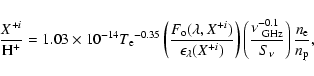
![\begin{displaymath}\left ( {[S {\sc iii}]_{33.4} \over [S {\sc iii}]_{18.7}} \ri...
...ilon_{33.4} \over \epsilon_{18.7}} {{S_4} \over {S_{\rm 3C}}},
\end{displaymath}](/articles/aa/full/2003/33/aah3840/img224.gif)
![\begin{figure}
\par\includegraphics[width=8.5cm,clip]{H3840F10.EPS}
\end{figure}](/articles/aa/full/2003/33/aah3840/img227.gif)
![\begin{figure}
\par\includegraphics[width=17cm,clip]{H3840F11.EPS}
\end{figure}](/articles/aa/full/2003/33/aah3840/img240.gif)