A&A 402, 781-789 (2003)
DOI: 10.1051/0004-6361:20030285
A. J. Díaz - R. Oliver - J. L. Ballester
Departament de Física, Universitat de les Illes Balears, 07122 Palma de Mallorca, Spain
Received 23 December 2002 / Accepted 20 February 2003
Abstract
High-resolution observations of quiescent filaments point out
that their fine structure is made of small-scale threads or fibrils.
These fibrils can be represented as thin loops having cool tops, i.e. the
prominence material, while the rest of the loop displays coronal
temperatures. Then, the stacking of these thin loops in the vertical
and horizontal directions gives place to the fine structure of
filaments. On the other hand, two-dimensional, high-resolution
observations of oscillations in filaments suggest that individual
fibrils or groups of fibrils may oscillate independently with their
own periods (Yi et al. 1991). Díaz et al. (2001, hereafter Paper I)
studied the
fast magnetohydrodynamic oscillations of a single and isolated
slab prominence fibril using a two-dimensional model with no
dependence in the y-direction. Here, we introduce a
completely different approach which allows us to build up a 3-dimensional
model for the fast magnetohydrodynamic oscillations of the fibril
configuration used in Paper I. As compared to the results
obtained in Paper I, two relevant new features appear; first of all,
the cut-off frequency varies with the longitudinal wavenumber, so
more modes can be trapped within the fibril; secondly, a much better
confinement of the energy of the modes within the fibril appears,
diminishing the leakage of energy towards neighbouring fibrils and
so difficulting their mutual excitation.
Key words: Sun: oscillations - Sun: magnetic fields - Sun: corona - Sun: prominences
High-resolution observations of quiescent filaments show very fine structures within their body, suggesting that they are composed of small-scale threads or fibrils. The existence of this internal structure in prominences was already suggested by Menzel & Evans (1953), was clarified with the improvement of observational capabilities (Engvold 1976; Engvold et al. 1987), and evidence for the presence of horizontal fine structures within prominences has been provided by Schmieder & Mein (1989), Schmieder et al. (1991) and Engvold (2001).
The existence of small amplitude, periodic velocity oscillations in
quiescent solar prominences is a well-known phenomenon and many
theoretical investigations have been undertaken to explain them (see
Engvold 2001; Oliver & Ballester 2002 for thorough
reviews about observations and theoretical developments). The periods
of oscillation are classified as short (
![]() ),
intermediate (
),
intermediate (
![]() )
and long
(
)
and long
(
![]() )
although this classification does not appear
to reflect the origin of the prominence exciter. In addition, it
appears to be well established that small amplitude, periodic changes
in solar prominences are of local nature, affecting only restricted
prominence areas (Tsubaki & Takeuchi 1986;
Tsubaki et al. 1987; Balthasar et al. 1988a;
Balthasar et al. 1988b; Balthasar et al. 1993; Thompson &
Schmieder 1991; Balthasar & Wiehr 1994; Terradas et al.
2002). Two-dimensional, high-resolution observations (Yi
et al. 1991; Yi & Engvold 1991) have even revealed that
individual fibrils or groups of fibrils may oscillate independently
with their own periods, which range between 3 and 20 min. Hence,
one of the basic questions in prominence seismology that remains
unanswered nowadays is whether periodic changes in prominences are
always associated with their fibril structure or not.
)
although this classification does not appear
to reflect the origin of the prominence exciter. In addition, it
appears to be well established that small amplitude, periodic changes
in solar prominences are of local nature, affecting only restricted
prominence areas (Tsubaki & Takeuchi 1986;
Tsubaki et al. 1987; Balthasar et al. 1988a;
Balthasar et al. 1988b; Balthasar et al. 1993; Thompson &
Schmieder 1991; Balthasar & Wiehr 1994; Terradas et al.
2002). Two-dimensional, high-resolution observations (Yi
et al. 1991; Yi & Engvold 1991) have even revealed that
individual fibrils or groups of fibrils may oscillate independently
with their own periods, which range between 3 and 20 min. Hence,
one of the basic questions in prominence seismology that remains
unanswered nowadays is whether periodic changes in prominences are
always associated with their fibril structure or not.
The first theoretical investigation of periodic prominence
perturbations taking into account the prominence fine structure was
performed by Joarder et al. (1997). In Paper I, a more
in-depth analytical and numerical study of this type of configuration
was performed. Essentially, the equilibrium is similar to that in
Joarder & Roberts (1992) with the difference that the plasma
slab has a limited height, so the configuration is reminiscent of a
thin thread with finite width and thickness. Nevertheless, the fibril
is infinite in the longitudinal (y-) direction of the structure. To
further simplify the problem, the influence of plasma pressure is
neglected in Joarder et al. (1997) and in Paper I (zero-![]() limit) and consequently the slow mode is
absent. Thus, one is left with the Alfvén and fast modes in a
plasma threaded by a transverse magnetic field and with no
longitudinal propagation (ky=0). The most important
conclusions extracted from Paper I are that prominence fibrils can
only support a few modes of oscillation, those with smaller frequency,
since only a few harmonics at most can be trapped inside the thin loop, and
that the spatial structure of the fundamental even and odd kink modes is
such that the velocity amplitude outside the fibril takes large values
over long distances.
limit) and consequently the slow mode is
absent. Thus, one is left with the Alfvén and fast modes in a
plasma threaded by a transverse magnetic field and with no
longitudinal propagation (ky=0). The most important
conclusions extracted from Paper I are that prominence fibrils can
only support a few modes of oscillation, those with smaller frequency,
since only a few harmonics at most can be trapped inside the thin loop, and
that the spatial structure of the fundamental even and odd kink modes is
such that the velocity amplitude outside the fibril takes large values
over long distances.
![\begin{figure}
\par\includegraphics[height=7cm,width=14cm,clip]{h4191f1.eps}\end{figure}](/articles/aa/full/2003/17/aah4191/img22.gif) |
Figure 1:
Sketch of the equilibrium configuration used in this study.
The grey zone represents the cold part of the loop, modeling the prominence
fibril. The density in the fibril,
|
| Open with DEXTER | |
In this paper, we have considered the same equilibrium model as in
Paper I, but the approach followed to study the fast MHD oscillations
of the fibril is completely different. Using the total pressure as the
dependent variable instead of the velocity components, a 3-dimensional wave
equation is obtained and by solving it we
construct a fully 3-dimensional model for the fast MHD modes of oscillation of
the fibril. Here, the simplest example is considered:
an equilibrium invariant in the y-direction (that leads to waves
propagating with dependence in the form
![]() ), while the
investigation of the effects of adding structure in this direction is
left for further work.
), while the
investigation of the effects of adding structure in this direction is
left for further work.
Our paper is organized as follows: in Sect. 2 the equilibrium model and the basic assumptions are described and also the fast wave equations obtained using our new approach are reviewed; in Sect. 3 the analytical solution suitable for this model is deduced and applied to the special case of independence on the y-coordinate to point out that this procedure leads to the same results as in Paper I; then, in Sect. 4 the results are presented and discussed, and finally in Sect. 5 our conclusions are drawn.
Following Paper I, we consider a single isolated fibril
which is modeled as a straight slab of total length 2L, made of a cold and
dense part (the prominence fibril itself) with length 2W and density
![]() ,
and a less dense coronal gas with density
,
and a less dense coronal gas with density
![]() occupying the rest of the thin loop. The width of the
structure is 2b, and it is embedded in the coronal environment,
with density
occupying the rest of the thin loop. The width of the
structure is 2b, and it is embedded in the coronal environment,
with density
![]() .
The loop is anchored in the
photosphere, so its footpoints are subject to line-tying conditions. Finally,
the plasma is permeated by a uniform magnetic field directed along the
prominence fibril. Because gravity is neglected, all other physical variables
(
.
The loop is anchored in the
photosphere, so its footpoints are subject to line-tying conditions. Finally,
the plasma is permeated by a uniform magnetic field directed along the
prominence fibril. Because gravity is neglected, all other physical variables
(![]() ,
T and p) are also uniform in each of the three regions. We also
assume invariance in the y-direction (Fig. 1).
,
T and p) are also uniform in each of the three regions. We also
assume invariance in the y-direction (Fig. 1).
As numerical values for the parameters defining the equilibrium model,
we have considered the thickness and length of the prominence
fibril
![]() -500 km and
-500 km and
![]() km, respectively,
and the total length of magnetic field lines
km, respectively,
and the total length of magnetic field lines
![]() -100 000 km, so that
-100 000 km, so that
![]() -0.01and
-0.01and ![]() 0.1-0.2. Moreover, typical density values are such
that
0.1-0.2. Moreover, typical density values are such
that
![]() and
and
![]() .
.
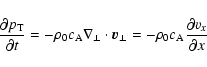
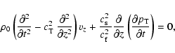
To derive a wave equation for this model the starting point are the perturbation
equations from Roberts (1991). We consider a uniform, static plasma with
unperturbed density ![]() and equilibrium magnetic field
and equilibrium magnetic field
![]() .
Next, linear, adiabatic perturbations about this equilibrium are
introduced and the magnetic field and pressure perturbations,
.
Next, linear, adiabatic perturbations about this equilibrium are
introduced and the magnetic field and pressure perturbations, ![]() and p,
are eliminated in favour of the velocity and the total pressure perturbations,
and p,
are eliminated in favour of the velocity and the total pressure perturbations,
![]() and
and
![]() ,
so the following equations are obtained,
,
so the following equations are obtained,
where the symbol ![]() stands for the components of the perturbed
velocity and the gradient perpendicular to
stands for the components of the perturbed
velocity and the gradient perpendicular to ![]() ,
,
![]() is the
sound speed,
is the
sound speed,
![]() the Alfvén speed and the other characteristic speeds are
defined as
the Alfvén speed and the other characteristic speeds are
defined as
![]() and
and
![]() .
.
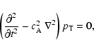
Next, we consider the limit
![]() ,
which implies
,
which implies
![]() ,
,
![]() and
and
![]() .
Notice also
that the total pressure is equal to the magnetic pressure, but
we are going to use the variable
.
Notice also
that the total pressure is equal to the magnetic pressure, but
we are going to use the variable
![]() through the paper.
Under this assumption, which is quite acceptable for coronal plasmas,
from Eq. (3) the component of
the perturbed velocity along the magnetic field, vz, is identically zero,
showing that the slow mode is absent in this low-
through the paper.
Under this assumption, which is quite acceptable for coronal plasmas,
from Eq. (3) the component of
the perturbed velocity along the magnetic field, vz, is identically zero,
showing that the slow mode is absent in this low-![]() plasma approximation.
plasma approximation.
Now, if we assume dependence of the variables on the y-coordinate and
select the velocity components as our dependent variables, a pair
of coupled partial differential equations are obtained. However, it is still
possible to write our expressions in terms of the total pressure perturbation
and have only one partial differential equation to solve (see Díaz et al. 2002). For this
reason,
![]() will be our main dependent variable in the following. Using the
result vz=0 and using Eq. (2) to eliminate
will be our main dependent variable in the following. Using the
result vz=0 and using Eq. (2) to eliminate
![]() from Eq. (1), the resulting equations are
from Eq. (1), the resulting equations are
so the oscillatory properties of the system can be determined by solving
Eq. (4) to obtain
![]() ,
after which all other perturbed
variables can be calculated (e.g. Eq. (5) gives
,
after which all other perturbed
variables can be calculated (e.g. Eq. (5) gives
![]() in terms of the total pressure perturbation).
We are only interested in oscillatory perturbations, so in
what follows a temporal dependence of the form
in terms of the total pressure perturbation).
We are only interested in oscillatory perturbations, so in
what follows a temporal dependence of the form
![]() is considered.
is considered.
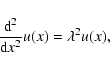
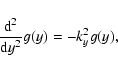
The standard method for solving partial differential equations like
Eq. (4) in a finite region is separation of variables.
Writing
![]() leads to the ordinary differential equations
leads to the ordinary differential equations
Next, we apply the boundary conditions, namely evanescence of perturbations
away from the
fibril in the x-direction (but not in the y-direction),
line-tying at ![]() and the jump conditions at the boundaries
and the jump conditions at the boundaries ![]() and
and ![]() .
This issue has been extensively treated in Paper I,
so we need not repeat all the details here. Nevertheless, it must be mentioned
that some of the boundary
conditions involve the perturbed velocity, which from Eq. (5) can
be eliminated in favour of
.
This issue has been extensively treated in Paper I,
so we need not repeat all the details here. Nevertheless, it must be mentioned
that some of the boundary
conditions involve the perturbed velocity, which from Eq. (5) can
be eliminated in favour of
![]() and so one ends up with restrictions on the
functions u(x) and h(z) (also see Díaz et al. 2002 for more
information).
and so one ends up with restrictions on the
functions u(x) and h(z) (also see Díaz et al. 2002 for more
information).
Owing to the symmetries about x=0 and
z=0, the problem can be solved in the region ![]() ,
,
![]() only. Following Joarder et al. (1997) and Paper I,
solutions with vx even/odd in x will be hereafter referred to as
kink/sausage modes. Moreover, there are two regions where
Eqs. (6)-(8) are to be solved, the fibril
one (labelled "l'') and the coronal one (labelled "c''). The fibril in turn
comprises the cool prominence material (labelled "p'') and the evacuated part
with hot coronal plasma (labelled "e''). When imposing the
boundary conditions at x=b it turns out that the solution of
Eq. (4) must
be a superposition of all the basis functions coming from
Eqs. (6)-(8), see Paper I and Díaz et al. (2002).
This superposition can be written in the form
only. Following Joarder et al. (1997) and Paper I,
solutions with vx even/odd in x will be hereafter referred to as
kink/sausage modes. Moreover, there are two regions where
Eqs. (6)-(8) are to be solved, the fibril
one (labelled "l'') and the coronal one (labelled "c''). The fibril in turn
comprises the cool prominence material (labelled "p'') and the evacuated part
with hot coronal plasma (labelled "e''). When imposing the
boundary conditions at x=b it turns out that the solution of
Eq. (4) must
be a superposition of all the basis functions coming from
Eqs. (6)-(8), see Paper I and Díaz et al. (2002).
This superposition can be written in the form
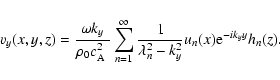
where the basis functions un(x), g(y) and hn(z) can be expressed as
(for even kink modes)
where ![]() is a normalization constant, An and Bn are constant
coefficients and
is a normalization constant, An and Bn are constant
coefficients and
![]() ,
,
![]() and
and
![]() are defined as
are defined as
with
![]() and
and ![]() substituted by the corresponding values in each of
the three regions (corona, prominence fibril and evacuated part of the loop).
This expression is different from that in Paper I because of
the inclusion of the wavenumber in the y-direction (ky).
substituted by the corresponding values in each of
the three regions (corona, prominence fibril and evacuated part of the loop).
This expression is different from that in Paper I because of
the inclusion of the wavenumber in the y-direction (ky).
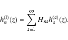
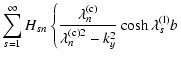
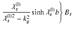
In order to fulfill the line-tying conditions, the outer solution must satisfy
The perturbed velocity can also be calculated from Eq. (5) and
turns out to be
Moreover, to match the solutions at x=b one should use
the Sturm-Liouville theorem, which states that the solutions to Eq. (8) with the line-tying boundary condition
are a complete basis set, so we can expand the inner z-dependent
functions in terms of the outer ones in the form
Therefore, the main differences with the analytical solution of Paper I
are that here the total pressure is used as the dependent variable, that
perturbations now have
y-dependence (see Eqs. (9), (11), (17) and
(18)) and that
![]() ,
,
![]() and
and
![]() in Eq. (13) have an extra contribution coming from the wavelength
in the y-direction. Consequently, the same applies to the dispersion
relation, Eq. (21).
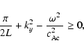
The first noticeable effect is that the cut-off
frequency is no longer a fixed value, but depends on ky. To show this point,
one needs to take into account that a mode
becomes leaky when
in Eq. (13) have an extra contribution coming from the wavelength
in the y-direction. Consequently, the same applies to the dispersion
relation, Eq. (21).
The first noticeable effect is that the cut-off
frequency is no longer a fixed value, but depends on ky. To show this point,
one needs to take into account that a mode
becomes leaky when
![]() and the first basis
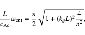
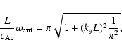
function to satisfy this condition is the one with n=1. Hence, the cut-off
appears when
and the first basis
function to satisfy this condition is the one with n=1. Hence, the cut-off
appears when
![]() ,
so using
Eqs. (13)-(15) the frequencies of trapped modes must satisfy (even modes)
,
so using
Eqs. (13)-(15) the frequencies of trapped modes must satisfy (even modes)
![\begin{figure}
\par\includegraphics[width=6.1cm,clip]{h4191f2a.eps}\hspace*{1.4c...
...eps}\hspace*{1.4cm}
\includegraphics[width=6.1cm,clip]{h4191f2d.eps}\end{figure}](/articles/aa/full/2003/17/aah4191/img97.gif) |
Figure 2:
Frequency of the kink even modes vs. ky for the set of
parameters W/L=0.1,
|
| Open with DEXTER | |
The solution developed in the last section can be checked in the limiting case
ky=0, which was the case solved in Paper I. However, the analytical
procedure here is different from that adopted in Paper I since we are now
solving a partial differential equation for
![]() ,
while the perturbed velocity
can only be obtained after the total pressure perturbation has been calculated.
We now prove that both solutions agree in spite of using different dependent
variables, which provides with a fine check of the present analysis.
,
while the perturbed velocity
can only be obtained after the total pressure perturbation has been calculated.
We now prove that both solutions agree in spite of using different dependent
variables, which provides with a fine check of the present analysis.
If we assume no dependence on the y-coordinate (ky=0), then from
Eq. (16) vy is identically zero and from Eq. (1) and
in the low-beta limit we obtain
Going back to
![]() ,
the system of equations in Eq. (21) now takes the simple form
,
the system of equations in Eq. (21) now takes the simple form
Finally, it is straightforward to show that the x- and z-dependence of the
perturbations in Paper I agree with those given by Eqs. (10) and
(12). It is only necessary to take into account that here un(x)appears in the total pressure perturbation, while in Paper I a function
with the same name appears in vx. Nevertheless the two functions are
different since we have seen, Eq. (25), that
![]() is related to the
derivative of vx with respect to x.
is related to the
derivative of vx with respect to x.
After having discussed some general properties of the modes, we turn our
attention to the solutions of the dispersion relation. First of all, the
variation
of the frequency of the modes with respect to the longitudinal
wavenumber, ky, is studied. Figure 2 shows this
behaviour for a set of fibril parameters in which the fibril thickness
(b/L) is modified.
![\begin{figure}
\par\includegraphics[width=6.5cm,clip]{h4191f3.eps}\end{figure}](/articles/aa/full/2003/17/aah4191/img101.gif) |
Figure 3:
Frequency of the fundamental kink even mode vs.
ky L, for the set of parameters W/L=0.1,
|
| Open with DEXTER | |
![\begin{figure}
\par\includegraphics[width=6.3cm,clip]{h4191f4.eps}\end{figure}](/articles/aa/full/2003/17/aah4191/img102.gif) |
Figure 4:
Frequency of the kink even modes vs. the fibril thickness,
b/L, for the set of parameters W/L=0.1,
|
| Open with DEXTER | |
The first important point to remark is that the cut-off frequency depends on
the y-component of the wavenumber (ky) in the form given by
Eq. (23). Therefore, the larger ky, the more non-leaky modes
can exist. Notice, however, that the frequency of the modes depends on ky
very slightly, except for some modes as they approach the cut-off frequency or
for very large ky (
![]() ,
say; Fig. 3).
As a consequence, the introduction
of propagation in the y-direction does not change drastically the frequency
of non-leaky modes, but makes it possible to trap other modes that are leaky in
the limit ky=0 for the same set of parameters (Paper I).
,
say; Fig. 3).
As a consequence, the introduction
of propagation in the y-direction does not change drastically the frequency
of non-leaky modes, but makes it possible to trap other modes that are leaky in
the limit ky=0 for the same set of parameters (Paper I).
These two effects (slight dependence of the frequency on ky and apparition of new trapped modes) can be appreciated in Fig. 4. The overall picture does not change very much when adding propagation in the y-direction to the model, except that the cut-off frequency is raised. In fact, if a parameter set different from that used in Fig. 4 is taken, the result is again that the existing mode frequencies for ky=0 (described in Paper I) are not noticeably affected, while the raising of the cut-off allows more modes to become trapped.
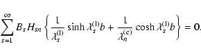
 |
Figure 5:
Surface plots of the fundamental kink even mode for the set of
parameters b/L=0.1, W/L=0.1,
|
| Open with DEXTER | |
![\begin{figure}
\par\includegraphics[width=7cm,clip]{h4191f6a.eps}\vspace*{4mm}
\...
...b.eps}\vspace*{4mm}
\includegraphics[width=7.2cm,clip]{h4191f6c.eps}\end{figure}](/articles/aa/full/2003/17/aah4191/img105.gif) |
Figure 6:
Cut across the centre of the fibril (z=0) of the solutions
in Fig. 5. Because of the jump conditions imposed at the interface
x=b, the derivative of both
|
| Open with DEXTER | |
Following the above discussion about the dispersion relation, the spatial
profiles of the different solutions are next studied. Here it should be
remarked that for
![]() all modes have both vx and vy non-zero,
see Eqs. (17) and (18). The spatial structure of the
fundamental kink even mode in an unrealistically thick fibril is displayed in
Fig. 5. Such as was mentioned before, the symmetries in the solutions
allow us to concentrate on the region
all modes have both vx and vy non-zero,
see Eqs. (17) and (18). The spatial structure of the
fundamental kink even mode in an unrealistically thick fibril is displayed in
Fig. 5. Such as was mentioned before, the symmetries in the solutions
allow us to concentrate on the region
![]() ,
,
![]() ,
although a finite spatial range across the fibril is used in our plots since
solutions decay exponentially in this direction. It can be seen in
Figs. 5 and 6 that the total pressure perturbation,
,
although a finite spatial range across the fibril is used in our plots since
solutions decay exponentially in this direction. It can be seen in
Figs. 5 and 6 that the total pressure perturbation,
![]() ,
and the x-component of the velocity, vx, are not derivable at the boundary
x=b and that vy is not even continuous there. It is also worthwhile
to remark that the higher ky, the more marked the discontinuity in the
derivative with respect to x of
,
and the x-component of the velocity, vx, are not derivable at the boundary
x=b and that vy is not even continuous there. It is also worthwhile
to remark that the higher ky, the more marked the discontinuity in the
derivative with respect to x of
![]() and vx at x=b. The normalization
constant in these figures has been fixed by the condition
and vx at x=b. The normalization
constant in these figures has been fixed by the condition
![]() .
.
![\begin{figure}
\par\includegraphics[width=7.2cm,clip]{h4191f7a.eps}\vspace*{4mm}...
...b.eps}\vspace*{4mm}
\includegraphics[width=7.2cm,clip]{h4191f7c.eps}\end{figure}](/articles/aa/full/2003/17/aah4191/img107.gif) |
Figure 7:
Cut across the centre of the fibril (z=0) of a)
|
| Open with DEXTER | |
The number of extrema and the spatial couplings that are found now are quite similar to those in Paper I: when two modes (with different spatial structure and thus with different number of extrema) approach in frequency because of the variation of a parameter, like b/L, there is a coupling and the modes exchange their spatial structure (i.e. the number of extrema in each direction).
![\begin{figure}
\par\includegraphics[width=7cm,clip]{h4191f8a.eps}\vspace*{4mm}
\includegraphics[width=7cm,clip]{h4191f8b.eps} .\end{figure}](/articles/aa/full/2003/17/aah4191/img108.gif) |
Figure 8:
Plots of vx for the fundamental kink
even mode, a) is a cut across the fibril at z=0 in logarithmic scale
and b) is a cut along the fibril at x=0. The parameters used are
b/L=0.001, W/L=0.1,
|
| Open with DEXTER | |
At this point one may wonder which is the reasonable range of values for ky.
So far we have concentrated in dimensionless values of this parameter of order
unity, but larger values of ky have also been considered. Hence,
we study how the relative amplitudes of the three relevant
magnitudes (
![]() from Eqs. (9), (17)
and (18)) change when ky is modified (Fig. 7).
First of all, if
from Eqs. (9), (17)
and (18)) change when ky is modified (Fig. 7).
First of all, if
![]() then
then
![]() and
and
![]() (in dimensionless units), so the velocity component in the
x-direction dominates. On the other hand, if
(in dimensionless units), so the velocity component in the
x-direction dominates. On the other hand, if
![]() then
then
![]() and
and
![]() ,
since
,
since
![]() from Eq. (13) so
from Eq. (13) so
![]() is small compared with
ky or
is small compared with
ky or ![]() in Eqs. (17) and (18), and as a
consequence both velocity polarisations are of the same order and quite large
in front of the
total pressure perturbation. Notice also that for ky large the modes tend to
become a surface wave as those in Roberts (1981).
However, for realistic values of b/L this transition is not noticeable unless
ky is rather large (about
in Eqs. (17) and (18), and as a
consequence both velocity polarisations are of the same order and quite large
in front of the
total pressure perturbation. Notice also that for ky large the modes tend to
become a surface wave as those in Roberts (1981).
However, for realistic values of b/L this transition is not noticeable unless
ky is rather large (about
![]() for b/L=0.001).
for b/L=0.001).
![\begin{figure}
\par\includegraphics[width=7.3cm,clip]{h4191f9a.eps}\hspace*{7mm}
\includegraphics[width=7.3cm,clip]{h4191f9b.eps}\end{figure}](/articles/aa/full/2003/17/aah4191/img119.gif) |
Figure 9:
Cut of vx a) in the z=0 direction and b) in
the x=0 direction, of the first kink even harmonic. The equilibrium
parameters are
b/L=0.01, W/L=0.1,
|
| Open with DEXTER | |
The most relevant fact coming from the inclusion of ky is that the cut-off
is raised, so we next study the variation of the spatial structure of the modes
near that frequency for ![]() .
In Paper I, only one confined mode
was present for a realistic range of parameters; this is clearly shown in
Fig. 4d with ky=0. Furthermore, for low values of ky(
.
In Paper I, only one confined mode
was present for a realistic range of parameters; this is clearly shown in
Fig. 4d with ky=0. Furthermore, for low values of ky(
![]() ,
say) there is still only one non-leaky mode in the system.
Figure 8 gives a comparison between
vx with ky=0 (Paper I), which from Eq. (25) is
continuous and derivable at the boundary x=b,
and vx with
,
say) there is still only one non-leaky mode in the system.
Figure 8 gives a comparison between
vx with ky=0 (Paper I), which from Eq. (25) is
continuous and derivable at the boundary x=b,
and vx with
![]() ,
which is not derivable at x=L.
The solution becomes more
confined as ky is increased, but it still has a long tail and attains
non-negligible values at a distance 100 times the fibril thickness for kyL=3.
,
which is not derivable at x=L.
The solution becomes more
confined as ky is increased, but it still has a long tail and attains
non-negligible values at a distance 100 times the fibril thickness for kyL=3.
It is also worthwhile studying the new array of confined modes that arise for
![]() .
As an example, we concentrate on the first harmonic in
Fig. 2c and plot cuts of the spatial
structure of vx (Fig. 9). This variable has three extrema in the
range
.
As an example, we concentrate on the first harmonic in
Fig. 2c and plot cuts of the spatial
structure of vx (Fig. 9). This variable has three extrema in the
range
![]() (Fig. 9b), but when the frequency goes far
from the cut-off as a consequence
of propagation in the y-direction, some structure develops
outside the fibril in the x-direction (Fig. 9a), because
the second basis
function, u2(x), also has a long decaying length. Again, the larger ky,
the more
confined the mode is in the x-direction (although perturbations reach large
distances from the fibril axis). On the other hand, in the z-direction
the amplitude in the evacuated part is larger than the amplitude in the dense
part (similar to what was found for some modes in Paper I). As ky is
increased, this effect becomes more noticeable, making this kind
of modes harder to detect because of their small amplitude in the prominence
plasma.
(Fig. 9b), but when the frequency goes far
from the cut-off as a consequence
of propagation in the y-direction, some structure develops
outside the fibril in the x-direction (Fig. 9a), because
the second basis
function, u2(x), also has a long decaying length. Again, the larger ky,
the more
confined the mode is in the x-direction (although perturbations reach large
distances from the fibril axis). On the other hand, in the z-direction
the amplitude in the evacuated part is larger than the amplitude in the dense
part (similar to what was found for some modes in Paper I). As ky is
increased, this effect becomes more noticeable, making this kind
of modes harder to detect because of their small amplitude in the prominence
plasma.
In this paper we present an analytical framework which allows us to set up a
3-dimensional
model for the study of fast modes in an isolated Cartesian fibril.
The problem has been solved using the same analytical techniques as in
Paper I, although following Díaz et al. (2002) the total
pressure perturbation has now been used as the main unknown.
In our discussion of the results we have emphasized the behaviour of
the dispersion relations and the spatial structure of the modes.
The inclusion of propagation in the y-direction (![]() )
in the model
has two relevant effects with respect to the results of Paper I:
)
in the model
has two relevant effects with respect to the results of Paper I:
Acknowledgements
A. J. Díaz, J. L. Ballester and R. Oliver acknowledge the financial support received from Spanish MCyT under grant BFM2000-1329.


 +
+ = 0,
= 0,