A&A 401, 1215-1222 (2003)
DOI: 10.1051/0004-6361:20030200
C. Sbarra1 - E. Carretti1 - S. Cortiglioni1 - M. Zannoni2 - R. Fabbri3 - C. Macculi1 - M. Tucci4
1 - IASF-CNR Bologna, via P. Gobetti 101, 40129 Bologna, Italy
2 -
IASF-CNR Milano, via Bassini 15, 20133 Milano, Italy
3 -
Dipartimento di Fisica, Università di Firenze, via Sansone 1,
50019 Sesto Fiorentino, Italy
4 -
Instituto de Fisica de Cantabria, Avda. Los Castros s/n,
39005 Santander, Spain
Received 18 December 2002 / Accepted 13 February 2003
Abstract
We describe a simple but effective iterative procedure
specifically designed to destripe Q and U Stokes parameter data as those collected
by the SPOrt experiment onboard the International Space Station (ISS).
The method is general enough to be useful for other experiments, both
in polarization and total intensity.
The only requirement for the algorithm to work properly is that the
receiver knee frequency must be lower than the
signal modulation frequency, corresponding in our case
to the ISS orbit period.
Detailed performances of the technique are presented in the
context of the SPOrt experiment, both in terms of added rms noise
and residual correlated noise.
Key words: cosmic microwave background - polarization - cosmology: observations - methods: data analysis - methods: numerical
Low frequency noise is known to affect all radiometers and to
induce correlations among successive samples of the measured signal,
leading to typical striping effects when producing sky maps.
It is characterised by a power-law
spectrum
![]() ,
with
,
with ![]() roughly in
the range
roughly in
the range
![]() depending on the noise
source. The total instrumental
noise power spectrum is usually specified in terms of
the knee frequency,
depending on the noise
source. The total instrumental
noise power spectrum is usually specified in terms of
the knee frequency, ![]() ,
at which the white and
low frequency components of
the noise are equal:
,
at which the white and
low frequency components of
the noise are equal:
For present and future space experiments primarily dedicated to
Cosmic Microwave Background (CMB) anysotropy
measurements, like MAP![]() and PLANCK
and PLANCK![]() ,
destriping techniques have already been set up to clean the Time
Ordered Data (TOD) from low
frequency noise. The impact of different scanning strategies
on the quality of final maps has been studied as well (Delabrouille 1998;
Maino et al. 1999).
,
destriping techniques have already been set up to clean the Time
Ordered Data (TOD) from low
frequency noise. The impact of different scanning strategies
on the quality of final maps has been studied as well (Delabrouille 1998;
Maino et al. 1999).
The problem of removing 1/f noise from the data stream
is even more important for experiments attempting measurements of CMB polarization (CMBP), where even a tiny amount of
residual correlated noise, at a
level negligible for investigations of CMB temperature anysotropy
(
![]() ), might distort the signal characteristics:
in the most favourable case the expected polarization level is
only in the order of 10% of the
temperature fluctuations. The first algorithm specifically designed
for destriping polarization data has been proposed by
Revenu et al. (2000), who extended to polarization data ideas previously
studied to destripe PLANCK anisotropy data (Delabrouille 1998).
), might distort the signal characteristics:
in the most favourable case the expected polarization level is
only in the order of 10% of the
temperature fluctuations. The first algorithm specifically designed
for destriping polarization data has been proposed by
Revenu et al. (2000), who extended to polarization data ideas previously
studied to destripe PLANCK anisotropy data (Delabrouille 1998).
![\begin{figure}
\par\includegraphics[angle=90,width=8.8cm]{h4185_f1a.ps}\par\vspace*{2mm}
\includegraphics[angle=90,width=8.8cm]{h4185_f1b.ps}
\end{figure}](/articles/aa/full/2003/15/aah4185/img18.gif) |
Figure 1:
Top: the sky, in Celestial coordinates, as scanned by SPOrt in
few orbits. Bottom:
pixel observing time (seconds) for 388 days of data taking.
The pixel size is about |
| Open with DEXTER | |
The SPOrt![]() experiment
onboard the ISS (Cortiglioni et al. 2002; Carretti et al. 2003)
is equipped with 4 correlation
polarimeters directly measuring the Q and U Stokes parameters in the 22-90 GHz frequency range, with
experiment
onboard the ISS (Cortiglioni et al. 2002; Carretti et al. 2003)
is equipped with 4 correlation
polarimeters directly measuring the Q and U Stokes parameters in the 22-90 GHz frequency range, with
![]() .
Besides providing polarization maps of Galactic
synchrotron, SPOrt
will try a first detection of CMBP on large angular scales
(
.
Besides providing polarization maps of Galactic
synchrotron, SPOrt
will try a first detection of CMBP on large angular scales
(
![]() ),
where the CMB E-mode power spectrum is particularly sensitive to the value
of the optical depth of the reionized medium
(Seljak 1997; Zaldarriaga et al. 1997). Such information cannot be
extracted from CMB temperature anisotropy data, nor from CMBP data taken by
balloon and ground-based experiments looking at small sky patches.
This makes CMBP
measurements on large angular scale of the utmost importance.
The algorithm presented here is particularly suited to SPOrt,
acting directely on Q and U Stokes parameter data.
),
where the CMB E-mode power spectrum is particularly sensitive to the value
of the optical depth of the reionized medium
(Seljak 1997; Zaldarriaga et al. 1997). Such information cannot be
extracted from CMB temperature anisotropy data, nor from CMBP data taken by
balloon and ground-based experiments looking at small sky patches.
This makes CMBP
measurements on large angular scale of the utmost importance.
The algorithm presented here is particularly suited to SPOrt,
acting directely on Q and U Stokes parameter data.
The SPOrt radiometers are
based on InP HEMT amplifiers, for which the low frequency noise
is known to have a 1/f-like spectrum (
![]() )
dominated
by transistor gain fluctuations (Wollack 1995), with knee frequencies
in the range 100-1000 Hz. However,
when using correlation techniques, the knee frequency is reduced
by a factor
)
dominated
by transistor gain fluctuations (Wollack 1995), with knee frequencies
in the range 100-1000 Hz. However,
when using correlation techniques, the knee frequency is reduced
by a factor
![]() ,
with
,
with
![]() and
and
![]() the instrumental offset and the system noise temperature,
respectively (Wollack & Pospiesalski 1998;
Carretti et al. 2001). The present state of the instrument already guarantees
a value
the instrumental offset and the system noise temperature,
respectively (Wollack & Pospiesalski 1998;
Carretti et al. 2001). The present state of the instrument already guarantees
a value
![]() Hz (Carretti et al. 2003),
close to the goal knee frequency of one tenth of the ISS
orbit frequency, i.e.
Hz (Carretti et al. 2003),
close to the goal knee frequency of one tenth of the ISS
orbit frequency, i.e.
![]() Hz.
Hz.
The SPOrt scanning strategy is bound to the ISS motion. The ISS orbit is tilted by
![]() with respect to the
Celestial equator and is characterized by a frequency
with respect to the
Celestial equator and is characterized by a frequency
![]() Hz.
The SPOrt antennae, looking at the zenit, will cover about 80% of the
sky under precessing circles intersecting each other. The nominal sampling
rate is 1 Hz, and
a sky map will be provided every 70 days in a
mission lasting at least 18 months.
Further details about the SPOrt sky coverage are shown in
Fig. 1.
Hz.
The SPOrt antennae, looking at the zenit, will cover about 80% of the
sky under precessing circles intersecting each other. The nominal sampling
rate is 1 Hz, and
a sky map will be provided every 70 days in a
mission lasting at least 18 months.
Further details about the SPOrt sky coverage are shown in
Fig. 1.
The iterative algorithm described in this paper has been specifically designed to destripe Q and U Stokes parameter data. It is general enough to be valid for any experiment where data are taken by scanning the sky at a frequency higher than the receiver knee frequency, and where different scans intersect each other in a sufficient number of points. Measurements of scalar quantities are easily handled.
The description of the algorithm is provided in Sect. 2, whereas Sect. 3 presents various tests of its performances and Sect. 4 summarises our conclusions.
The only assumptions our algorithm relies upon is that the radiometer is stable during the signal modulation period (the time needed to complete one orbit in case of SPOrt), so that the instrumental offset does not change significantly during this time, and there is enough overlap between different orbits. In such a case the noise can be split in two parts: for time scales shorter than the orbit period (high frequencies) it is essentially white, whereas for longer timescales (low frequencies) it also contains the 1/f component, which we model as a different constant offset for each orbit. A simple iterative procedure is then applied to remove these offsets from the TOD before map-making. The map-making itself consists in averaging the cleaned TOD corresponding to the same sky pixel after rotating them into a fixed reference frame. Parallel transport to the center of each pixel is also implemented, as described by Bruscoli et al. (2002), before averaging, and can optionally be switched on, though it is not strictly necessary for the portion of sky covered by SPOrt. It would be mandatory if polar caps were included in the accessible region. The time needed to simulate 1 year of SPOrt data taking with the nominal sampling rate of 1 Hz, destripe the TOD and produce Q and U clean maps is about 10 min on a 1.3 GHz Pentium III equipped with a 4 GB RAM when using 10 destriping cycles, and increases by 2.5 min for each additional bunch of 10 iteration cycles.
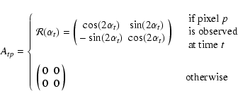
Each datum consists of a (![]() ,
,
![]() )
pair as measured
in the polarimeter
reference frame: the same sky point, when seen from different orbits, shows
different (
)
pair as measured
in the polarimeter
reference frame: the same sky point, when seen from different orbits, shows
different (![]() ,
,
![]() )
values even in absence of noise. The standard longitude-latitude
fixed reference frame (Berkhuijsen 1975) is used
when considering the real sky emission, which is projected into an N-pixel
map.
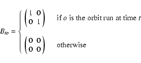
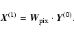
Our M TOD, collected during R orbits about
the Earth, are used to build an M-vector Y
of measured (
)
values even in absence of noise. The standard longitude-latitude
fixed reference frame (Berkhuijsen 1975) is used
when considering the real sky emission, which is projected into an N-pixel
map.
Our M TOD, collected during R orbits about
the Earth, are used to build an M-vector Y
of measured (![]() ,
,
![]() )
pairs:
)
pairs:
 |
(3) |
 |
(4) |
 |
(5) |
 |
(6) |
 |
(7) |
 |
(8) |
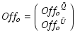
If we knew the sky emission vector X we could use it to obtain the offset
vector OFF
by inverting Eq. (2).
Of course, estimating the noise offsets would not be worthwhile if we
already knew the true sky
emission. However, to start we can guess a 0-order sky emission
![]() ,
the most neutral choice being a null vector; then obtain a 0-order offset
estimate, and subtract it from our measurements to get a 0-order
cleaned TOD; from this compute
,
the most neutral choice being a null vector; then obtain a 0-order offset
estimate, and subtract it from our measurements to get a 0-order
cleaned TOD; from this compute
![]() ,
the 1st-order
estimate of the real sky emission, and iterate the cycle.
,
the 1st-order
estimate of the real sky emission, and iterate the cycle.
Starting from Eq. (2) and
following Tegmark (1997b), the best
estimators for the offset vector and the signal matrix
can be written:
| |
= | (9) | |
| = | (10) |
| |
= | (11) | |
| = | (12) |
In the more general case of non-uniform white noise, i.e.
when the noise covariance
matrix
![]() has unequal diagonal elements,
the matrices
has unequal diagonal elements,
the matrices
![]() and
and
![]() become (Tegmark 1997b)
become (Tegmark 1997b)
| |
= | (13) | |
| = | (14) |
In any case the first offset estimate writes:
| (15) |
| (16) |
 |
(17) |
| |
= | (18) | |
| = | (19) |
The proof that the procedure is effective has been obtained numerically,
as described in detail in the next section. Destriping measurements of total
intensity (or, in general, any other
scalar quantity) can be simply
performed by replacing pairs with scalars in the
previously
defined vectors, and rotation matrices with scalar 1.
The average sky signal is lost when destriping maps
of scalar quantities. However, for maps of polarization data like Q and Uit can be kept provided the polarimeter
reference frame rotates about the fixed frame while running along each
orbit, as in the case of SPOrt. This is a nice feature, especially
when measuring foreground contributions.
![\begin{figure}
\par\includegraphics[width=8.8cm,clip]{h4185_f2.eps}
\end{figure}](/articles/aa/full/2003/15/aah4185/img67.gif) |
Figure 2:
|
| Open with DEXTER | |
We test the method with numerical simulations of the data stream expected from about one year of SPOrt data taking.
As real sky emission we consider both CMB and synchrotron radiation, both
convolved with a ![]() Gaussian beam. Other foregrounds are
expected to be less important at the frequencies and
angular scales covered by SPOrt (Tegmark et al. 2000; Lazarian
& Prunet 2002) and are not included.
Gaussian beam. Other foregrounds are
expected to be less important at the frequencies and
angular scales covered by SPOrt (Tegmark et al. 2000; Lazarian
& Prunet 2002) and are not included.
CMB emission is generated by the
CMBFAST![]() package
according to a
package
according to a ![]() CDM cosmological model
with
CDM cosmological model
with
![]() ,
,
![]() ,
,
![]() ,
,
![]() ,
,
![]() and no contributions from gravitational waves.
For the synchrotron radiation
we use Q and U map templates at 22 GHz
developed by Bernardi et al. (2003) and featuring a
and no contributions from gravitational waves.
For the synchrotron radiation
we use Q and U map templates at 22 GHz
developed by Bernardi et al. (2003) and featuring a
![]() K.
The
polarized intensity
peak emission
is about 130
K.
The
polarized intensity
peak emission
is about 130 ![]() K.
The main ingredients of the template are total intensity low frequency data
(Haslam et al. 1982; Reich 1982),
from which the syncrothron polarized intensity is extracted,
and optical starlight data (Heiles 2000), from which polarization
angles are derived.
The template frequency has been chosen to correspond to the
SPOrt channel where synchrotron emission is expected to be most important.
K.
The main ingredients of the template are total intensity low frequency data
(Haslam et al. 1982; Reich 1982),
from which the syncrothron polarized intensity is extracted,
and optical starlight data (Heiles 2000), from which polarization
angles are derived.
The template frequency has been chosen to correspond to the
SPOrt channel where synchrotron emission is expected to be most important.
Noise streams to be added to the sky signal are built in the frequency
space, where their Fourier coefficients are generated
according to the spectrum defined in Eq. (1),
with ![]() ,
and transported to the time domain via FFT.
Our code allows us to calculate the angle between our polarimeters
and the longitude-latitude fixed reference frame for each data sample, and
to set the sampling
frequency from the nominal rate (1 Hz) to any other rate while keeping the
SPOrt nominal istantaneous sensitivity of
,
and transported to the time domain via FFT.
Our code allows us to calculate the angle between our polarimeters
and the longitude-latitude fixed reference frame for each data sample, and
to set the sampling
frequency from the nominal rate (1 Hz) to any other rate while keeping the
SPOrt nominal istantaneous sensitivity of
![]() (Carretti et al. 2003).
In the tests described here the sampling rate
was set to 1 Hz, and the SPOrt observing time was about 1 year.
The final output of our simulations are TOD and noise arrays,
clean Q and U signal maps to investigate the effects of SPOrt partial
sky survey, Q and U maps containing both signal and noise before and after
destriping as well as a hit map to evaluate the time spent over each
map pixel.
We use the HEALPix
(Carretti et al. 2003).
In the tests described here the sampling rate
was set to 1 Hz, and the SPOrt observing time was about 1 year.
The final output of our simulations are TOD and noise arrays,
clean Q and U signal maps to investigate the effects of SPOrt partial
sky survey, Q and U maps containing both signal and noise before and after
destriping as well as a hit map to evaluate the time spent over each
map pixel.
We use the HEALPix![]() pixelisation scheme (Gorski et al. 1998)
with
pixelisation scheme (Gorski et al. 1998)
with
![]() to
ensure the effects of pixelisation are negligible when compared to the
antenna beam (the pixel size of the output maps is
to
ensure the effects of pixelisation are negligible when compared to the
antenna beam (the pixel size of the output maps is ![]()
![]() ).
We test the destriping efficiency on simulated maps
by evaluating the residual low frequency noise
in terms of added rms noise with respect to the white noise case,
angular correlation functions
).
We test the destriping efficiency on simulated maps
by evaluating the residual low frequency noise
in terms of added rms noise with respect to the white noise case,
angular correlation functions
![]() (X=Q,U) and
power spectra
(X=Q,U) and
power spectra
![]() (Y=E,B).
(Y=E,B).
![\begin{figure}
\par\includegraphics[angle=90,width=8.8cm,clip]{h4185_f3a.ps}\par...
...ce*{2mm}
\includegraphics[angle=90,width=8.8cm,clip]{h4185_f3b.ps}
\end{figure}](/articles/aa/full/2003/15/aah4185/img82.gif) |
Figure 3:
Noise simulated maps before (top) and after (bottom) destriping, for
the case
|
| Open with DEXTER | |
![\begin{figure}
\par\includegraphics[width=18cm,clip]{h4185_f4.eps}
\end{figure}](/articles/aa/full/2003/15/aah4185/img83.gif) |
Figure 4:
Average and 1 |
| Open with DEXTER | |
To avoid edge effects due to partial sky coverage and to efficiently take
into account the presence of noise, even in case of non uniform sky coverage,
we primarly test our destriping technique by studying the two-point
correlation functions
![]() (X=Q,U) measured from our simulated
maps. We sample the correlation functions with about one degree of angular
resolution according to the expression:
(X=Q,U) measured from our simulated
maps. We sample the correlation functions with about one degree of angular
resolution according to the expression:
 |
(20) |
 |
(21) |
The
![]() power spectra can be recovered from the measured
correlation functions by
integration (Kamionkowski et al. 1997; Zaldarriaga 1998):
power spectra can be recovered from the measured
correlation functions by
integration (Kamionkowski et al. 1997; Zaldarriaga 1998):
![\begin{displaymath}C_{\ell}^{E}=\int^{\pi}_0\left[C^{ Q}(\theta)F^1_{\ell,2}(\th...
...U}(\theta)F^2_{\ell,2}(\theta)\right]\sin\theta~ {\rm d}\theta
\end{displaymath}](/articles/aa/full/2003/15/aah4185/img90.gif) |
(22) |
![\begin{displaymath}C_{\ell}^{B}=\int^{\pi}_0\left[C^{ U}(\theta)F^1_{\ell,2}(\th...
...Q}(\theta)F^2_{\ell,2}(\theta)\right]\sin\theta~ {\rm d}\theta
\end{displaymath}](/articles/aa/full/2003/15/aah4185/img91.gif) |
(23) |
![\begin{figure}
\par\includegraphics[width=17.2cm,clip]{h4185_f5.eps}
\end{figure}](/articles/aa/full/2003/15/aah4185/img96.gif) |
Figure 5: Average of noise power spectra measured from the same maps used to make Fig. 4 (top). In the bottom panel the residual noise in percentage of the measured white noise level is shown as a function of the multipole. |
| Open with DEXTER | |
To check for the presence of spurious correlations introduced by our algorithm
and depending on the underlying signal,
as a first test we run the destriping code over CMB and Synchrotron
maps containing no
noise. The test confirms our algorithm subtracts the average signal
from the input map when dealing with scalar quantities
(CMB temperature in our case), whereas
nothing is lost in our Q and U maps.
We then analyse the difference between the destriped and the original maps
as a function of the number of iterations of the destriping cycle.
Should no residual
effects be present, these differences would asimptotically
become null for Q and U maps, and a
constant number corresponding to the average of
the input signal for scalar maps.
Indeed, the maximum pixel-to-pixel difference,
which depends on the level of the underlying signal, decreases
with increasing number of iterations.
In particular, the spurious noise introduced when destriping maps of
synchrotron emission at 22 GHz, i.e. the SPOrt frequency where
the Galactic contribution is expected to be higher, becomes negligible
also for CMBP after about 20 loops, reaching the tiny level of
few nK after 30 loops. More details are shown in
Table 1, both in terms of
peak-to-peak amplitude and rms of spurious noise. For comparison, the
peak-to-peak amplitude and rms of the
underlying signal maps are shown as well.
|
|
cmb | sync | ||
| peak-to-peak | rms | peak-to-peak | rms | |
| amplitude [ |
[ |
amplitude [ |
[ |
|
| 10 |
|
|
1.1 | 0.3 |
| 20 |
|
|
|
|
| 30 |
|
|
|
|
| 40 |
|
|
|
|
| 3 | 0.5 | 170 | 20 | |
The same conclusions can be derived by
inspecting the angular correlation functions
![]() (X=Q,U) of
the spurious noise: they are not flat, but
deviations from a flat null function decrease with increasing number of
iteration cycles and can be made negligible after
about 10 (20) loops when destriping CMB (synchrotron) Q, U maps.
(X=Q,U) of
the spurious noise: they are not flat, but
deviations from a flat null function decrease with increasing number of
iteration cycles and can be made negligible after
about 10 (20) loops when destriping CMB (synchrotron) Q, U maps.
The effectiveness of our destriping technique is then tested on simulated maps containing only noise, in the following cases:
One possible way to quantify the residual correlated noise
after destriping is measuring
the fractional excess pixel noise with respect to the
case of purely white noise. Results are shown in Table 2
for two different values of
the knee frequency, corresponding to the SPOrt goal knee frequency,
![]() Hz, and the SPOrt orbit frequency,
Hz, and the SPOrt orbit frequency,
![]() Hz,
the latter representing a very conservative case.
Hz,
the latter representing a very conservative case.
|
|
Before Destriping | After Destriping |
|
|
310% | 6% |
|
|
35% | <1% |
Another way to quantify the residual correlated noise is
measuring and inspecting the two-point correlation
functions
![]() of
simulated Q and U noise maps.
Averages and 1
of
simulated Q and U noise maps.
Averages and 1![]() bands of 500 correlation functions
bands of 500 correlation functions
![]() measured from maps containing both white and 1/f noise, before and
after destriping, are compared
to the purely white noise case in Fig. 4 for the
same knee frequencies as in the previous test.
The correlation functions
measured from maps containing both white and 1/f noise, before and
after destriping, are compared
to the purely white noise case in Fig. 4 for the
same knee frequencies as in the previous test.
The correlation functions
![]() are similar and are not shown.
As expected, the correlated noise is strongly reduced by the destriping
procedure, the residuals falling within the statistical error of
the white noise case for
are similar and are not shown.
As expected, the correlated noise is strongly reduced by the destriping
procedure, the residuals falling within the statistical error of
the white noise case for
![]() .
The correlation functions for the case of purely 1/f noise are similar
to the white plus 1/f case everywhere but at 0 distance, and
are not shown.
.
The correlation functions for the case of purely 1/f noise are similar
to the white plus 1/f case everywhere but at 0 distance, and
are not shown.
If the noise statistical properties are known, its two-point correlation
function after destriping
can be calculated with Monte Carlo techniques and subtracted
from the measured values before integrating, the recovering of
signal power spectra presenting no huge problems.
However, the residual correlated noise also increases
the expected error on measured quantities. In our case the rms
of correlation functions measured from many noise maps
is increased by roughly 4% (11%), for
![]() Hz
(
Hz
(
![]() Hz),
with respect to the case of purely
white noise.
Hz),
with respect to the case of purely
white noise.
For completeness, and to ease the comparison with other
methods, average noise power spectra, obtained from the correlation functions
used to make Fig. 4, are
shown in Fig. 5, though they carry the same information
as the correlation functions.
As expected, even for the largest knee frequency
the
![]() power spectrum
of the residual noise is close to that of purely white noise.
The region of low multipoles is the most sensitive to low frequency
residuals, some
contributions being always found here also after the application of
other destriping
techniques (Maino et al. 1999).
The excess noise, in percentage of the measured white noise level,
is shown in the bottom panel of Fig. 5 as a function
of the multipole.
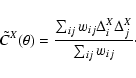
The theoretical white noise level can be calculated as follows:
power spectrum
of the residual noise is close to that of purely white noise.
The region of low multipoles is the most sensitive to low frequency
residuals, some
contributions being always found here also after the application of
other destriping
techniques (Maino et al. 1999).
The excess noise, in percentage of the measured white noise level,
is shown in the bottom panel of Fig. 5 as a function
of the multipole.
The theoretical white noise level can be calculated as follows:
 |
(24) |
Finally, Fig. 6 shows the increment,
due to the presence
of residual correlated noise, in the rms of measured noise power
spectra, after destriping, in percentage of the rms of purely
white noise power spectra, again as a function of the multipole.
![\begin{figure}
\par\includegraphics[width=8.8cm,clip]{h4185_f6.eps}
\end{figure}](/articles/aa/full/2003/15/aah4185/img121.gif) |
Figure 6: Increment, due to the presence of residual correlated noise, in the rms of measured noise power spectra, after destriping, as a function of the multipole, in percentage of the rms of purely white-noise power spectra. |
| Open with DEXTER | |
The performances of the technique,
studied on simulated SPOrt data by analysing both the measured
![]() two-point correlation functions and
the measured
two-point correlation functions and
the measured
![]() power
spectra, are comparable to those of other methods
based on
power
spectra, are comparable to those of other methods
based on ![]() minimisation.
Computer time is not an issue, no matrix
inversions being involved.
minimisation.
Computer time is not an issue, no matrix
inversions being involved.
Power spectra are recovered from the measured two-point correlation functions by integration, this method being implemented here for the first time for polarization data. It has the advantages of avoiding edge problems arising when using the ANAFAST code and to allow for pixel weighting in case of non uniform sky coverage.
Acknowledgements
This work has been carried out in the context of the SPOrt program, which is funded by the Italian Space Agency. We thank B. Audone and F. Amisano for useful discussions and the anonimous referee for good suggestions. We acknowledge the use of CMBFAST and HEALPix packages.
![\begin{displaymath}S(f)=\sigma_0^2\left[1+\left(\frac{f_{\rm k}}{f}\right)^{\beta}\right]
\end{displaymath}](/articles/aa/full/2003/15/aah4185/img14.gif)