 |
(1) |
A&A 387, 1153-1160 (2002)
DOI: 10.1051/0004-6361:20020379
J. E. R. Costa 1,2 - A. V. R Silva2 - A. Lüdi3 - A. Magun3
1 - INPE - Instituto Nacional de Pesquisas Espaciais,
S. J. Campos, SP - Brazil
2 -
CRAAM - Universidade Presbiteriana Mackenzie, S. Paulo, SP - Brazil
3 -
IAP, University of Bern - Switzerland
Received 31 January 2002 / Accepted 4 March 2002
Abstract
Beam patterns of radio telescopes with moderate (arcmin)
angular resolution in the millimeter and sub-millimeter range are difficult to
measure as only weak sources are available in that spectral range. This
limitation can be overcome with the deconvolution of radial scans over the
knife edge of the solar limb which provides beam profiles down to secondary
lobe levels. Numerous applications, such as quick adjustments and checkups of
telescope optics, efficiency estimates and the reconstruction of partially
unresolved structures such as active regions, become possible. We investigate
here the inverse problem of the beam profile reconstruction from the beam
convolution with the solar limb. With simple derivatives of solar radial scans
we obtained line integrals of the beam profile under different scanning
angles. Reconstruction methods used in tomography of filtered reverse
projection allowed us then to obtain beam profiles down to the level of
secondary lobes. Tests of the algorithm were carried out with simulated data
and solar scans that are verified by planet observations and terrestrial
beam pattern measurements.
Key words: instrumentation: miscellaneous - telescopes - Sun: radio radiation
Theoretical calculations of the antenna gain and beam patterns for reflectors are only guidelines for the characterization of antenna beams and must therefore be verified with external radio sources. Direct (Lüdi et al. 2000) or holographic measurements (Fuhr et al. 1979) in the mm/sub-mm range over horizontal propagation paths with powerful transmitters provide a high dynamic range. However, at sub-mm wavelengths the atmospheric absorption becomes significant in the far field of typically several kilometers. Therefore, occasionally, transmitters on board satellites are used, whenever available (Baars 1973 and references therein). Problems can arise from the coherent nature of the test signal (standing waves in the telescope optics), and a precise determination of the absolute antenna gain is not possible.
On the other hand, only a few celestial, point-like radio sources such as Jupiter, Venus and Mars are available for beam measurements of antennas with intermediate angular (arc minute) resolution. However, for these relatively weak sources and low antenna sensitivities, long integration times are required.
Therefore the Sun has also been explored to obtain beam profiles from the deconvolution of solar scans (Baars 1973) and dual beam measurements (Lindsey & Roellig 1991). This method takes advantage of the sharp knife edge of the solar limb and the large signal available. Solar observations are in general possible when a radome or other setups are available that prevent overheating of the front-end. Thus, deconvolved beams can be used in many calibration and image reconstruction issues, as has already been mentioned by Baars (1973) and Lindsey & Roellig (1991). Although the precise adjustment of antenna optics is best done with strong point sources, changes in the coma side lobes during axial focusing (Ruze 1965; Baars 1973) can be detected from solar scans once the beam profile has been determined. The measurement of beam efficiency and gain needs external sources with known brightness temperatures. These can be provided by quiet Sun regions and the Moon.
Besides presenting a sharp knife edge for beam measurements, the solar disc can also be used in the cm, mm and sub-mm range for pointing purposes, as it has a very accurately known position, and no extended emission from the corona is expected to disturb the circular limb fit, e.g. Costa et al. (1999), Lindsey & Roellig (1991). The width of limb brightening or darkening features is typically far below the telescope resolution of a few arc minutes and those features are consequently smeared out by beam convolution.
Our analysis will focus on the capabilities and the limitations of the tomographic method for reconstructing the beam shape from simple derivatives of solar scans. The Solar Submillimetric Telescope, SST (Kaufmann et al. 2001), provided solar scan data for beam reconstruction. Its designed beam width of 4 and 2 arcmin at the observing frequencies of 212 GHz and 405 GHz respectively, and its collecting area of 1.8 m2 fits well for the beam pattern determination from solar scans. For comparison, also observations with Venus and direct beam pattern measurements with a transmitter have been included in our study.
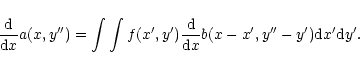
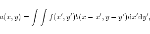
The convolution and deconvolution is mathematically well described in many text
books (e.g., Bracewell 1965). In the bi-dimensional case of a beam pattern
f(x,y) convolved with an extended source b(x,y) the convolved (measured)
pattern is given by
![\begin{figure}
\includegraphics[width=7.2cm,clip]{2332f1.eps}
\end{figure}](/articles/aa/full/2002/21/aa2332/img8.gif) |
Figure 1:
Schematic representation of solar radial scans, crossing the
circular solar disc brigthness distribution b(x,y) at the center.
A beam contour, f(x,y), is shown at the scanning angle
|
| Open with DEXTER | |
| (5) |
![\begin{figure}
\includegraphics[width=9cm,clip]{2332f2.eps}\end{figure}](/articles/aa/full/2002/21/aa2332/img13.gif) |
Figure 2: The effects of the limb shape on the convolution between a circular beam (with zero brightness outside the beam) and a circular (R and L) and respectively straight solar limb (V). The two circular limbs represent the opposite sides of the Sun crossing the beam (inset b)). A ratio of 0.25 between the beam (8 arcmin) and the solar disk (32 arcmin) diameters has been assumed. Part a) presents the convolution for V (solid line) as well as for R and L (dotted and dashed lines). In the center we show the relative errors of the averages for R and L in relation to the convolution (V). In part c) we show the maximum relative error as a function of the ratio between beam and solar disk diameter. |
| Open with DEXTER | |
In order to explore the effects of limb curvature on the measured scan values, a
numerical convolution between a constant circular beam profile and different
solar limb shapes has been carried out (Fig. 2). Inset b, illustrates
the limbs of a circular solar disk (R and L) and a solar disk with a straight
limb (V). Scans are carried out in radial directions. The convolution results
are shown as a solid (V) and dashed/dotted lines (R and L) in Fig. 2a for a beam diameter of 8 arcmin (beam to solar diameter ratio
equals 0.25). For small ratios, effects of curvature can be minimized by
averaging scans crossing the limb from opposite sides (R and L). This is
illustrated by the small difference (in %) between the average convolution
and the convolution with a straight solar limb. The total rms error (as a
consequence of the assumption of a straight limb) versus the beam to solar
diameter ratio is shown in Fig. 2c. For a ratio of less than .25
the error is less than 1%.
![\begin{figure}
\includegraphics[width=9cm,clip]{2332f3.eps}
\end{figure}](/articles/aa/full/2002/21/aa2332/img14.gif) |
Figure 3: Reconstruction of a structured test beam pattern (top left) with 8 radial cuts whose profiles are shown as solid lines. Dashed lines represent the reconstructed beam profiles for a straight limb. The polar angles of the scan profiles are shown in the top-right corner of each plot and the test pattern. |
| Open with DEXTER | |
The scan signal is contaminated by noise which is of radiometric and
atmospheric origin. It severely limits the accuracy with which beam patterns
can be reconstructed. The relative noise of a receiver is given by the
radiometer formula,
![]() .
The receivers used
for solar scanning have a bandwidth B of 1 GHz and an integration time
.
The receivers used
for solar scanning have a bandwidth B of 1 GHz and an integration time ![]() of 2 ms. The solar signal
of 2 ms. The solar signal ![]() is in our setup approximately half the total
noise signal
is in our setup approximately half the total
noise signal ![]() .
From this follows a relative error
.
From this follows a relative error
![]() of approximately 10-3 that, theoretically, can be decreased by longer
integration. At the same time, however, the scan time must be increased by the
same factor if spatial resolution is not to deteriorate. Unfortunately, longer
scan times lead to an increase in noise levels due to atmospheric
scintillation (Lüdi & Magun 2000). It increases with scanning time and can not
easily be predicted. It must be therefore measured separately between sets of
scans as it depends on atmospheric conditions and scan duration. For short
scan times of only a few seconds and a non-turbulent atmosphere we found that
for an integration time of up to 100 ms, the relative error in atmospheric noise
can be neglected, so that an error of 10-4 for a 100 ms integration time
is realistic.
of approximately 10-3 that, theoretically, can be decreased by longer
integration. At the same time, however, the scan time must be increased by the
same factor if spatial resolution is not to deteriorate. Unfortunately, longer
scan times lead to an increase in noise levels due to atmospheric
scintillation (Lüdi & Magun 2000). It increases with scanning time and can not
easily be predicted. It must be therefore measured separately between sets of
scans as it depends on atmospheric conditions and scan duration. For short
scan times of only a few seconds and a non-turbulent atmosphere we found that
for an integration time of up to 100 ms, the relative error in atmospheric noise
can be neglected, so that an error of 10-4 for a 100 ms integration time
is realistic.
![\begin{figure}
\includegraphics[width=9cm,clip]{2332f4.eps}\end{figure}](/articles/aa/full/2002/21/aa2332/img20.gif) |
Figure 4: Reconstructed beams from solar radial scan maps for four of the SST beams after the repair of the antenna (April 18, 2001). Beam 5 operates at 405 GHz, the remaining at 212 GHz. The isocontours are 10, 20, 30, 40, 50, 60, 70, 80, 90, and 99% levels. |
| Open with DEXTER | |
In order to explore our reconstruction algorithm with noise contaminated test
data, we have generated an artificial, highly structured beam profile as
shown in the top-left corner of Fig. 3 without noise,
to which white Gaussian
noise of varying amplitude has later been added (Table 1).
A circular, constant
emission source with a diameter of 32 arcmin was
convolved with the test beam in 18 radial directions (scans) every 10![]() and
reconstructed by using the filtered backprojection described in
Kak (1979). An example of the reconstructed beam (dashed line) is
presented in Fig. 3 (without noise), together with the original
input (solid line).
Eight cross sections of the reconstructed beam are shown, with the polar angle
of the slices printed in the top right corner. The differences between the
two profiles are small,
approximately 4.6% rms (-13.4 dB), with maximum errors up to 12% (-9.2 dB) relative to beam maximum. The errors are certainly due to the limb
curvature because if a straight solar limb is used the reconstruction is
perfect. Although the full beam width of 5.12 arcmin is used and the beam
pattern is highly structured, spatial details down to approximately 20 arcsec can be recovered.
and
reconstructed by using the filtered backprojection described in
Kak (1979). An example of the reconstructed beam (dashed line) is
presented in Fig. 3 (without noise), together with the original
input (solid line).
Eight cross sections of the reconstructed beam are shown, with the polar angle
of the slices printed in the top right corner. The differences between the
two profiles are small,
approximately 4.6% rms (-13.4 dB), with maximum errors up to 12% (-9.2 dB) relative to beam maximum. The errors are certainly due to the limb
curvature because if a straight solar limb is used the reconstruction is
perfect. Although the full beam width of 5.12 arcmin is used and the beam
pattern is highly structured, spatial details down to approximately 20 arcsec can be recovered.
By adding noise, the reconstruction will quickly be destroyed when the
relative error rises significantly for error levels above 10-4. Table 1 summarizes the errors in the reconstructed test beam for different
relative noise levels in the fictive input scan data for a 19.2 arcsec
sampling step.
|
|
Max. Error (dB) | rms (dB) |
| 10-3 | -1.1 | -5.1 |
| 10-4 | -8.5 | -12.2 |
| 10-5 | -8.9 | -14.0 |
We have also repeated the reconstruction of Fig. 3 using a limb brightening in the hypothetical solar brightness distribution. Using a 10% limb brightening with 1.5 arcmin width the differences between the two reconstructions are negligible (<0.1%).
The Solar Submillimetric Telescope, SST (Kaufmann et al. 2001) operates
with 6 receivers, 4 at 212 GHz and 2 at 405 GHz with system noise
temperatures of about 3000 K when looking onto the sky. Due to the
requirement that the 212 GHz beams intersect at half power levels
beams 2, 3, and 4 have a taper of 3 dB only, which leads to enhanced side
lobe levels. The expected nominal beam patterns were 4 and 2 arcmin wide
at 212 GHz and 405 GHz respectively. They have been measured by scanning
an intense transmitter in the far field Lüdi et al. (2000) of
the antenna, with
planet and solar scans. The latter were used to reconstruct beam patterns
which then were compared to the transmitter and planet measurements.
![\begin{figure}
\includegraphics[width=9cm,clip]{2332f5.eps}\end{figure}](/articles/aa/full/2002/21/aa2332/img23.gif) |
Figure 5: Comparison of the reconstructed SST beam from solar scans with the observation of Venus on April 18, 2001. The panels represent integrated scans of Venus in azimuth and elevation (thick solid line) with one sigma error bars on the left. For comparison, slices in azimuth and elevation of the beam patterns, reconstructed from solar radial scans (regular solid line), are superimposed. |
| Open with DEXTER | |
![\begin{figure}
\includegraphics[width=13cm,clip]{2332f6.eps}\end{figure}](/articles/aa/full/2002/21/aa2332/img24.gif) |
Figure 6: Comparison of a SST beam pattern (beam 2), reconstructed (left panel) from solar maps with the transmitter measurements (right panel), obtained in September 1999, before the antenna was repaired. The spatial sampling frequency for the reconstructed beam is 24 arcsec, that of the transmitter map 75 and 47 arcsec in azimuth and elevation, respectively (right panel). The contour levels shown are from 0.2 through 0.9 with a step width of 0.1. |
| Open with DEXTER | |
For a source size much smaller than the beam diameter, the convolution of the beam with the source provides the beam shape. In April 2001, several scans of planet Venus were done just after a map of the Sun was obtained. The latter consists of 18 radial scans, each with a duration of 16 s and a sampling step of 46 arcsec. Each solar scan was normalized at Sun center in order to minimize signal fluctuations caused by atmospheric scintillation and changes in opacity due the movement of the Sun. The reconstructed patterns for the four central beams on this day are shown as contour plots in Fig. 4. The coma lobe with less than 10% observed in the top right corner of each panel is probably caused by a small axial and/or lateral offset of the sub-reflector from the focal point. In order to compare the reconstructed beams with planet scans, we have obtained slices in azimuth and elevation from the reconstructed beam. These are plotted as thick solid lines in Fig. 5. Since the planet emission is too weak to be observed in a single scan, 200 scans (40 min of total duration) had to be integrated, resulting in a rms uncertainty that is represented by vertical bars in each panel. The averaged scans in azimuth and elevation are shown as thin lines for the 4 central beams. The spatial resolution for these averages is 43 arcsec (spatial resolution), similar to that of the solar scans used for the reconstruction of the beam.
As can be seen from Fig. 5, the agreement of the overall beam shape is generally good with a deviation of less than 10% of peak maximum. The elevation scans of Venus show prominent side lobes, mainly in beams 2 and 5. Although the differences are compatible with the error bars, the reconstructed profiles here are, in general, smoother probably due to the spatial under sampling of the observations. Nevertheless, these secondary features are partially evident in the reconstruction although with lower intensity.
Yet another check of the reconstruction algorithm from solar scans is by comparing the recovered beams with those obtained by direct beam pattern measurements with the help of strong transmitters, placed in the far field (Lüdi et al. 2000). The measurements were carried out at the astronomical site of El Leoncito (2550 m asl) with excellent atmospheric seeing conditions.
The solar maps, used for reconstruction, consist of 18 radial scans. The reconstructed map of beam 2, as an example, is shown in Fig. 6, the left panel. This map was taken in September 1999, before the SST antenna was repaired. On the same day, a few hours later, the antenna pattern was measured with the transmitter (Fig. 6, right) for comparison. Although not all radial solar scans crossed the Sun center (offsets up to 1 arcmin) the reconstructed and directly measured beam shapes agree well down to -7 db of the beam maximum and show that the reconstruction is capable of detecting side lobes down to a level of 20%. Meanwhile the beam shape has improved noticeably since the last optimization campaign which occurred on October 2000, as clearly evident from Fig. 4.
For small diameter antennas, the radio telescope sensitivity in the mm/sub-mm range strongly limits the direct beam shape determination with planets, especially when low side lobe levels are of concern. In this respect, simple derivatives of raster scans of the Sun or the Moon can be useful. However, a much better beam determination can be achieved when using the beam reconstruction technique presented here. Limb curvature imposes systematic errors, which for a ratio of beam width to the solar diameter of .25 (present case study), are less than approximately 0.2%. Thus, for noiseless measurements of the beam shape, typical reconstruction scenarios, as presented in our simulation, can recover spatial structures in the beam down to the level of -12.0 dB rms.
Another important source of (statistical) errors is receiver noise and the variation of the measured signal due to atmospheric scintillation. For an integration time of 100 ms and a scan time of not more than a few seconds, atmospheric noise can be neglected. Under good seeing conditions the relative noise level in the scan data is 10-4. According to Table 1 this noise level leads to a mean statistical error in the beam reconstruction of approximately 0.5% rms (-12 db), that quickly increases for higher noise levels. Fast scans with a high sampling rate can reduce the atmospheric noise and at the same time allow either further integration or higher spatial resolution. The magnitude of the systematic and statistical errors corresponds well with what has been found from our tests.
Further improvements of the proposed beam reconstruction can be done by (a) combining radial scans with scans in azimuth and elevation or other cross sections; (b) by optimizing the scan duration and integration time and (c) by taking advantage of the multi beam capability of SST that may be used to correct for atmospheric effects. We emphasize that the beam reconstruction from solar scans, as presented here, is very useful when beam mapping with a strong transmitter in the antenna far field is not possible, or if long integration times for planet measurements cannot be tolerated. This is especially true for the quick optimization of telescope optics down to side lobe levels of the order of -10 db.
Acknowledgements
We are grateful to P. Kaufmann for stimulating this research and to all members of the SST team, in particular to J.-P. Raulin, E. Correia, A. Marun and P. Pereyra for their participation in the April 2001 observations after the antenna was repaired. We also thank C. G. Giménez de Castro for important discussions and digital solutions for the SST control programs. SST is partially supported by Brazilian agency FAPESP.