A&A 385, 337-364 (2002)
DOI: 10.1051/0004-6361:20011817
Cosmological hydrodynamics with adaptive mesh refinement
A new high resolution code called RAMSES
R. Teyssier
Commissariat à l'Énergie Atomique, Direction
des Sciences de la Matière, Service d'Astrophysique,
Centre d'Études de Saclay, L'orme des Merisiers, 91191 Gif-sur-Yvette Cedex, France
and
Numerical Investigations in Cosmology (NIC group), CEA Saclay, France
Received 18 June 2001 / Accepted 12 December 2001
Abstract
A new N-body and hydrodynamical code, called RAMSES, is presented. It
has been designed to study structure formation in the universe with
high spatial resolution. The code is based on Adaptive Mesh
Refinement (AMR) technique, with a tree-based data structure allowing
recursive grid refinements on a cell-by-cell basis. The N-body solver
is very similar to the one developed for the ART code
(Kravtsov et al. 1997), with minor differences in the exact
implementation. The hydrodynamical solver is based on a second-order
Godunov method, a modern shock-capturing scheme known to compute
accurately the thermal history of the fluid component. The accuracy
of the code is carefully estimated using various test cases, from pure
gas dynamical tests to cosmological ones. The specific refinement
strategy used in cosmological simulations is described, and potential
spurious effects associated with shock waves propagation in the
resulting AMR grid are discussed and found to be negligible. Results
obtained in a large N-body and hydrodynamical simulation of structure
formation in a low density  CDM universe are reported,
with 2563 particles and
CDM universe are reported,
with 2563 particles and
 cells in the AMR grid,
reaching a formal resolution of 81923. A convergence analysis of
different quantities, such as dark matter density power spectrum, gas
pressure power spectrum and individual haloe temperature profiles,
shows that numerical results are converging down to the actual
resolution limit of the code, and are well reproduced by recent
analytical predictions in the framework of the halo model.
cells in the AMR grid,
reaching a formal resolution of 81923. A convergence analysis of
different quantities, such as dark matter density power spectrum, gas
pressure power spectrum and individual haloe temperature profiles,
shows that numerical results are converging down to the actual
resolution limit of the code, and are well reproduced by recent
analytical predictions in the framework of the halo model.
Key words:
gravitation - hydrodynamics - methods: numerical - cosmology:
theory -
cosmology: large-scale structure of Universe
1 Introduction
Numerical simulations of structure formation in the universe are now
widely used to understand the highly non-linear nature of
gravitational clustering. Dark matter is believed to be the dominant
component in the mass of the cosmological density field, with only a small
fraction (say 10%) in baryons. At intermediate scales, such as
galaxy clusters, dark matter still dominates the total gravitational
mass, but the introduction of a gaseous component appears to be
unavoidable, since X-ray or Sunyaev-Zeldovich observations of the hot
intracluster medium give us strong constraints on the structure of
galaxy clusters. On smaller scales, gas cooling and fluid dynamics
play a dominant role in the structure of galaxy-size object. Although
baryons can be described to first order as a hydrostatic ionized
plasma trapped in dark matter potential wells, the complexity of
hydrodynamical processes such as shock heating, atomic radiation
cooling and, ultimately, star formation requires an accurate treatment
of the baryonic component.
For a cosmological simulation to be realistic, high mass and spatial
resolution are needed. While the former is related to the initial
number of degrees of freedom (usually "particles'' or
"wavelengths'') in the computational volume, the latter is usually
related to the numerical method specifically used to compute the
particles trajectory. For a  universe, using a sufficiently
large volume of, say, 100 Mpc h-1 aside, we need at least 2563particles to describe
universe, using a sufficiently
large volume of, say, 100 Mpc h-1 aside, we need at least 2563particles to describe  galaxies with 100 particles. In
order to resolve the internal radial structure of such haloes with at
least 10 resolution elements, we need a spatial resolution of 10 kpc h-1 or equivalently a dynamical range of 104.
galaxies with 100 particles. In
order to resolve the internal radial structure of such haloes with at
least 10 resolution elements, we need a spatial resolution of 10 kpc h-1 or equivalently a dynamical range of 104.
The Particle-Mesh method (Hockney & Eastwood 1981; Klypin & Shandarin 1983) is perhaps the
simplest and fastest N-body algorithm for solving gravitational
dynamics, but it is limited by computer resources to a dynamical range
of 103. The P3M method (Hockney & Eastwood 1981; Efstathiou et al. 1985) can reach a higher
spatial resolution, by adding a small scale component to the PM force,
directly computed from the two-body interactions ("Particle-Particle'')
between neighboring particles. This method suffers however from a
dramatic increase in CPU time as clustering develops and as short
range forces become dominant. An improvement of this method was
therefore developed for the AP3M code (Couchman 1991): a hierarchy
of recursively refined rectangular grids is placed in clustered
regions where a local PM solver is activated to speed up the PP
calculations. Another N-body method which can achieve high dynamical
range is the TREE code (Barnes & Hut 1986; Bouchet & Hernquist 1988), which properly sort
neighboring particles in a recursive tree structure. Long-range
interactions are computed using multipole expansion and low resolution
nodes of the tree, while short range interactions are computed using a
PP approach between particles belonging to the same leaf of the tree.
The idea of using Adaptive Mesh Refinement (AMR) for N-body methods
appears as a natural generalization of both AP3M and TREE codes, since
they use a hierarchy of nested grids to increase the spatial
resolution locally. The recently developed ART code
(Kravtsov et al. 1997) offers, in this respect, the first implementation
of a grid-based high-resolution N-body code, where the mesh is defined
on a recursively refined spatial tree. ART takes advantage of both
the speed of a mesh-based Poisson solvers and the high-dynamical range
and flexibility obtained with a tree structure. Since no PP force is
considered in the ART method, the resolution is not uniform (as
opposed to AP3M and TREE codes), but proportional to the local cell
size of the grid. The grid is continuously refined or de-refined in
the course of the simulation, to ensure that the mean number of
particles par cell remains roughly constant (around 10). This
"quasi-Lagrangian'' approach ensures that two-body relaxation remains
unimportant (Knebe et al. 2000).
The gaseous component, baryons, can be described using one of several
hydrodynamical methods widely used today in cosmology. They can be
divided into three groups: Lagrangian schemes, Eulerian schemes and
intermediate schemes.
1- Lagrangian schemes or quasi-Lagrangian schemes (Gnedin 1995; Pen 1995) are based on a moving mesh that closely follows the geometry of
the flow for a constant number of grid points. The grid adapts itself
to collapsing fluid elements, but suffers from severe mesh distortion
in the non linear stage of gravitational clustering
(Gnedin & Bertschinger 1996). The coupling with one of the aformentioned N-body
solvers is also non-trivial (ibid).
2- Eulerian schemes are usually based on a uniform Cartesian mesh, which
make them suitable for a coupling with the traditional, low-resolution
PM solver (Cen 1992; Ryu et al. 1993; Teyssier et al. 1998; Chieze et al. 1998). They suffer
however from limited dynamic range.
3- Smooth Particles Hydrodynamics (SPH) can be thought as an
intermediate solution. This is a particle-based method, which follows
the Lagrangian evolution of the flow, but in which resolution elements
are defined as appropriate averages over 50 neighboring particles
(Gingold & Monaghan 1977; Evrard 1988; Hernquist & Katz 1989). This ``smoothing kernel''
defines the effective Eulerian resolution of the method. The SPH
method offers also the possibility of a straightforward coupling to
particle-based N-body solver like the AP3M or TREE codes. The main
drawback of the SPH method is its relative poor discontinuity
capturing capabilities (one needs at least 50 particles per resolution
element in order to properly describe sharp features, like shock waves
or contact surfaces) and the fact that it relies on the
artificial viscosity method to capture shock waves.
One of the most promising hydrodynamical methods at this time is the
AMR scheme, described originally in Berger & Oliger (1984) and
Berger & Collela (1989). The original AMR method is an Eulerian hydrodynamics
scheme, with a hierarchy of nested grids covering high-resolution
regions of the flow. The building blocks of the computational grid
are therefore rectangular patches of various sizes, whose positions
and aspects ratio are optimized with respect to flow geometry, speed
and memory constraints. Let's call this spatial structure
"patch-based AMR''. An alternative method was proposed by several
authors (see Khokhlov and reference therein) where parent
cells are refined into children cells, on a cell-by-cell basis. As
opposed to the original patch-based AMR, let us call this last method
"tree-based AMR'', since the natural data structure associated to
this scheme is a recursive tree structure. The resulting grid follows
complex flow geometry more closely, at the price of a data management
which is more complicated than patch-based AMR. These two different
adaptive mesh structures can be coupled to any grid-based fluid
dynamics scheme. It is worth mentioning that modern high-resolution
shock capturing methods are all grid-based and have number of
interesting features: they are stable up to large Courant numbers,
they are striclty conservative for the Euler equations and they
are able to capture discontinuities within only few cells. Among
several schemes, higher order Godunov methods appear to be more
accurate and to be easy to generalize in 3 dimensions.
The original patch-based AMR, based on the Piecewise Parabolic Method
(PPM: a third-order Godunov scheme), was recently adapted to cosmology
(Bryan & Norman 1997; Abel et al. 2000). The hydrodynamical scheme was coupled to
the AP3M N-body solver (without using the PP interaction module).
This choice is natural since both codes use a set of rectangular
patches to cover high-resolution regions of the flow.
In this paper, an alternative solution is explored: coupling a
tree-based AMR hydrodynamical scheme to the N-body solver developed
for the ART code (Kravtsov et al. 1997). This solution seems indeed more
suitable for the hierarchical clustering picture where a very complex
geometry builds up, with a large number of small clumps merging
progressively to form large virialized haloes and filaments. The
number of grids required to cover efficiently all these small haloes
is so large, that it renders a patch-based approach less efficient.
In this paper, a newly developed N-body and hydrodynamical code,
called RAMSES, is presented. It is a tree-based AMR using the "Fully
Threaded Tree'' data structure of Khokhlov (1998). The N-body
solver is largely inspired by the ART code (Kravtsov et al. 1997), with
some differences in the final implementation. The hydrodynamical
solver is a second-order Godunov scheme for perfect gases (also called
Piecewise Linear Method or PLM). In Sect. 2, the
N-body and hydrodynamical algorithms developed for RAMSES are briefly
described, with emphasis put on the original solutions discovered in
the course of this work. In Sect. 3, results obtained
by RAMSES for standard test cases are presented, demonstrating the
accuracy of the method. Pure hydrodynamical problems are considered
first, showing that shocks and contact surfaces are well captured by
the tree-based AMR scheme.
Great care is taken to demonstrate that refining the mesh in shock
fronts can be avoided in cosmological contexts. Indeed, potentially
spurious effects associated to the AMR grid remains low enough to
apply the method safely using refinements in high density regions
only. In Sect. 4, results of a large cosmological
simulation using 2563 particles, with coupled gas and dark matter
dynamics, are reported and compared to various analytical
predictions. In Sect. 5, the results presented in
this paper are summarized, and future projects are discussed.
2 Numerical methods
The modules used in RAMSES can be divided into 4 parts: the AMR
service routines, the Particle Mesh routines, the Poisson solver
routines and the hydrodynamical routines. The dimensionality, noted
 ,
can be anything among 1, 2 or 3.
,
can be anything among 1, 2 or 3.
The fundamental data structure in RAMSES is called a "Fully Threaded
Tree'' (FTT) (Khokhlov 1998). Basic elements are not single cells,
but rather groups of
 sibling cells called octs.
Each oct belongs to a given level of refinement labeled
sibling cells called octs.
Each oct belongs to a given level of refinement labeled  .
A
regular Cartesian grid, called the coarse grid, defines the base of
the tree structure (
.
A
regular Cartesian grid, called the coarse grid, defines the base of
the tree structure ( ). In order to access all octs of a given
level, octs are sorted in a double linked list. Each oct at level
points to the previous and the next oct in the level linked
list, but also to the parent cell at level
). In order to access all octs of a given
level, octs are sorted in a double linked list. Each oct at level
points to the previous and the next oct in the level linked
list, but also to the parent cell at level  ,
to the
,
to the
 neighboring parent cells at level
and to
the
child octs at level
neighboring parent cells at level
and to
the
child octs at level  .
If a cell has no
children, it is called a leaf cell, and the pointer to the
child oct is set to null. Otherwise, the cell is called a
split cell. In order to store this particular tree structure
in memory, one needs therefore 17 integers per oct for
.
If a cell has no
children, it is called a leaf cell, and the pointer to the
child oct is set to null. Otherwise, the cell is called a
split cell. In order to store this particular tree structure
in memory, one needs therefore 17 integers per oct for
 ,
or equivalently 2.125 integers per cell.
,
or equivalently 2.125 integers per cell.
In RAMSES, time integration can be perfomed in principle for each
level independantly. Only two time stepping algorithms have been
implemented so far: a single time step scheme and an adaptive time
step scheme. The single time step algorithm consists in integrating
the equations from t to
 ,
with the same time step
,
with the same time step
 for all levels. The adaptive time step algorithm, on the
other hand, is similar to a "W cycle'' in the multigrid terminology.
Each level is evolved in time with its own time step, determined by a
level dependant CFL stability condition. Consequenty, when level
is advanced in time using one coarse time step, level
for all levels. The adaptive time step algorithm, on the
other hand, is similar to a "W cycle'' in the multigrid terminology.
Each level is evolved in time with its own time step, determined by a
level dependant CFL stability condition. Consequenty, when level
is advanced in time using one coarse time step, level
 is advanced in time using two time steps, level
  using 4 time steps, and so on. An additional constraint on these
level dependant time steps comes from synchronization, namely
using 4 time steps, and so on. An additional constraint on these
level dependant time steps comes from synchronization, namely
 .
.
Within one time step and for each level, each operation is perfomed in
the following way: a sub-sample of octs is first gathered from the
tree. Gathered cells can then be modified very efficiently on vector
or parallel architectures. Finally, updated quantities are scattered
back to the tree. When one needs to access neighboring cells (in
order to compute gradients for example), it is straightforward to
obtain the neighboring oct addresses from the tree, and then to
compute the neighboring cell addresses.
The two main routines used to dynamically modify the AMR structure at
each time step are now described.
2.1.1 Building the refinement map
The first step consists of marking cells for refinement according to
user-defined refinement criteria, within the constraint given
by a strict refinement rule: any oct in the tree structure has to be
surrounded by
 neighboring parent cells. Thanks to
this rule, a smooth transition in spatial resolution between levels is
enforced, even in the diagonal directions. Practically, this step
consists in three passes through each level, starting from the finer
level
neighboring parent cells. Thanks to
this rule, a smooth transition in spatial resolution between levels is
enforced, even in the diagonal directions. Practically, this step
consists in three passes through each level, starting from the finer
level
 down to the coarse grid .
- 1.
- If a split cell contains a children cell that is marked or
already refined, then mark it for refinement;
- 2.
- Mark the
neighboring cells;
- 3.
- If any cell satisfies the user-defined refinement criteria,
then mark it for refinement.
One key ingredient still missing in this procedure is the so-called
"mesh smoothing''. Usually, refinement are activated when gradients
(or second derivatives) in the flow variables exceed a given
threshold. The resulting refinement map tends to be "noisy'',
especially in smooth part of the flow where gradients fluctuates
around the threshold. Khokhlov (1998) describes a very
sophisticated method based on a reaction-diffusion operator applied on
the refinement map. I prefer to use here the simpler approach of
Kravtsov et al. (1997) in the ART code, where a cubic buffer is expanded
several times around marked cells. The number of times one
applies the smoothing operator on the refinement map is obviously a
free parameter. This parameter is noted
 .
In the ART
code, this operator is applied twice at each time step. In RAMSES, it
is usually applied only once, since, as we see below, boundary
conditions are defined for each level in a slightly more sophisticated
way than in ART, using buffer regions (see Sect. 2.2.3).
Therefore, the extra mesh smoothing used in ART can be thought as a
way of creating the equivalent of the buffer regions in RAMSES.
.
In the ART
code, this operator is applied twice at each time step. In RAMSES, it
is usually applied only once, since, as we see below, boundary
conditions are defined for each level in a slightly more sophisticated
way than in ART, using buffer regions (see Sect. 2.2.3).
Therefore, the extra mesh smoothing used in ART can be thought as a
way of creating the equivalent of the buffer regions in RAMSES.
Note that the exact method implemented here and in the ART code leads
to a convex structure for the resulting mesh, that is likely to
increase the overall stability of the algorithm. Note also that only
refinement criteria are necessary in RAMSES: no de-refinement
criteria need to be specified by the user. This is an important
difference compared to other approaches (Khokhlov 1997; 1998).
The next step consists in splitting or destroying children cells
according to the refinement map. RAMSES performs two passes through
each level, starting from the coarse grid ,
up to the finer
grid
 :
:
- 1.
- If a leaf cell is marked for refinement,
then create its child oct;
- 2.
- If a split cell is not marked for refinement,
then destroy its child oct.
Creating or destroying a child oct is a time-consuming step, since it
implies reorganizing the tree structure. Thanks to the double linked
list associated to the FTT tree structure, this is done very
efficiently by first disconnecting the child oct from the list, and
then reconnecting the list in between the previous and next octs.
Note however that this operation can not be vectorized. It is
important to stress that this operation is applied at each time step,
but for a very small number of octs. In other word, at each
time step, the mesh structure is not rebuilt from scratch, but it is
slightly modified, in order to follow the evolution of the flow.
Since the refinement map has been carefully built during the last
step, the refinement rule should be satisfied by construction. This is
however not the case if one uses the adaptive time step method
described in Sect. 2.3.2. In this case, a final check
is performed before splitting leaf cells. If the refinement rule is
about to be violated, leaf cells are not refined.
The N-body scheme used in RAMSES is similar in many aspects to the ART
code of Kravtsov et al. (1997). Since the ART code was not publicily
available at the time this work was initiated, a new code had to be
implemented from scratch. I briefly recall here the main ingredients
of the method, outlining the differences between the two
implementations.
A collisionless N-body system is described by the Vlasov-Poisson
equations, which, in terms of particles (labeled by "p''), reads
 |
(1) |
Grid-based N-body schemes, such as the standard PM, are usually
decomposed in the following steps:
- 1.
- Compute the mass density
 on the mesh using a "Cloud-In-Cell''
(CIC) interpolation scheme;
on the mesh using a "Cloud-In-Cell''
(CIC) interpolation scheme;
- 2.
- Solve for the potential
 on the mesh using the Poisson equation;
- 3.
- Compute the acceleration on the mesh using a standard finite-difference
approximation of the gradient;
- 4.
- Compute each particle acceleration using an inverse
CIC interpolation scheme;
- 5.
- Update each particle velocity according to its acceleration;
- 6.
- Update each particle position according to its velocity.
The specific constraints of a tree-based AMR N-body solver are now
discussed in more details.
Since we are dealing with an AMR grid, we need to know which particle
is interacting with a given cell. This is done thanks to a particle
linked list. Particles belong to a given oct, if their position fits
exactly into the oct boundaries. All particles belonging to the same
oct are linked together. In order to build this linked list, we have
to store the position of each oct in the tree structure. Moreover,
each oct needs to have access to the address of the first particle in
the list and to the total number of particles contained in its
boundaries. We need therefore to store these two new integers in the
FTT tree structure.
The particle linked list is built in a way similar to the TREE code:
particles are first divided among the octs sitting at the coarse level
.
Each individual linked list is then recursively divided
among the children octs, up to the finer level
 .
Going from level
to level
implies removing from the
linked list particles sitting within split cell boundaries. Going
from level
to level
implies reconnecting the children
linked lists to the parent one. In the adaptive time step case, in
order to avoid rebuilding the whole tree from the coarse level,
particle positions are checked against parent octs boundaries and, if
necessary, are passed to neighboring octs using the information stored
in the FTT tree.
.
Going from level
to level
implies removing from the
linked list particles sitting within split cell boundaries. Going
from level
to level
implies reconnecting the children
linked lists to the parent one. In the adaptive time step case, in
order to avoid rebuilding the whole tree from the coarse level,
particle positions are checked against parent octs boundaries and, if
necessary, are passed to neighboring octs using the information stored
in the FTT tree.
The density field is computed using the CIC interpolation scheme
(Hockney & Eastwood 1981). For each level, particles sitting inside level
boundaries are first considered. This can be done using the level
particle linked list. Particles sitting outside the current
level, but whose clouds intersect the corresponding volume are then
taken into account. This is done by examining particles sitting
inside neighboring parent cells at level .
Note that in
this case the size of the overlapping cloud is the one of level particles. In this way, for a given set of particle positions, the
resulting density field at level
is exactly the same as that of
a regular Cartesian mesh of equivalent spatial resolution.
2.2.3 Solving the Poisson equation
Several methods are described in the literature to solve for the
Poisson equation in the adaptive grids framework (Couchman 1991; Jessop et al. 1994; Kravtsov et al. 1997; Almgren et al. 1998; Truelove et al. 1998). In RAMSES, as in the ART
code, the Poisson equation is solved using a "one-way interface''
scheme (Jessop et al. 1994; Kravtsov et al. 1997): the coarse grid solution never
"sees'' the effect of the fine grids. The resulting accuracy is the
same as if the coarse grid were alone. Boundary conditions are passed
only from the coarse grid to the fine grid by a linear interpolation.
For each AMR level, the solution should therefore be close to the one
obtained with a Cartesian mesh of equivalent spatial resolution, but
it can not be better in any way. A better accuracy would be
obtained using a two-way interface scheme, as the one described for
example in Truelove et al. (1998). Such a sophisticated improvement
of the Poisson solver is left for future work.
The Poisson equation at the coarse level is solved using standard Fast
Fourier Transform (FFT) technique (Hockney & Eastwood 1981), with a Green
function corresponding to Fourier transform of the
 -points finite difference approximation of the Laplacian. For
fine levels (
-points finite difference approximation of the Laplacian. For
fine levels ( ), the potential is found using a relaxation
method similar to the one developed for the ART code: the Poisson
equation is solved using the
-points finite difference
approximation of the Laplacian, with Dirichlet boundary conditions. In
RAMSES, boundary conditions are defined in a temporary buffer region
surrounding the level domain, where the potential is computed from
level
through a linear reconstruction.
), the potential is found using a relaxation
method similar to the one developed for the ART code: the Poisson
equation is solved using the
-points finite difference
approximation of the Laplacian, with Dirichlet boundary conditions. In
RAMSES, boundary conditions are defined in a temporary buffer region
surrounding the level domain, where the potential is computed from
level
through a linear reconstruction.
Using these specific boundary conditions, the potential can be
computed using any efficient relaxation method. In RAMSES, the
Gauss-Seidel (GS) method with Red-Black Ordering and Successive Over
Relaxation (Press et al. 1992) is used. In two dimensions, for unit mesh
spacing, the basic GS writes as
 |
(2) |
This iteration is applied first to update the potential for "black''
cells defined by i odd and j odd or i even and j even, and
then to update the potential for "red'' cells defined by i odd and
j even or i even and j odd. Finally, the result is
"over-corrected'' using the so-called over-relaxation parameter

 |
(3) |
The speed of the algorithm relies on the correct choice for both
and the initial guess
 .
For a regular
.
For a regular
 Cartesian mesh, the optimal over-relaxation parameter is known to be
(Press et al. 1992)
Cartesian mesh, the optimal over-relaxation parameter is known to be
(Press et al. 1992)
 |
(4) |
where  for Dirichlet boundary conditions and
  for
periodic boundary conditions. For an irregular AMR grid, the situation
is more complicated, since the computational volume is covered by
irregular mesh patches. The over-relaxation parameter has to be found
empirically. An interesting way of determining the optimal value for
is to estimate the average size <L> of these patches, and
to use it in formula (4) in place of N. It was found to
work very well in practice.
for
periodic boundary conditions. For an irregular AMR grid, the situation
is more complicated, since the computational volume is covered by
irregular mesh patches. The over-relaxation parameter has to be found
empirically. An interesting way of determining the optimal value for
is to estimate the average size <L> of these patches, and
to use it in formula (4) in place of N. It was found to
work very well in practice.
The initial guess is obtained from the coarser level
through
a linear reconstruction of the potential. In this way, the solution
at large scale is correctly captured at the very beginning of the
relaxation process. Only the shortest wavelengths need to be further
corrected.
A question that arises naturally is: when do we reach convergence?
Since our Poisson solver is coupled to a N-body system, errors due to
the CIC interpolation scheme are dominant in the force calculation. As
soon as the residuals are smaller than the CIC induced errors, further
iterations are unnecessary. For cosmological simulations, this is
obtained by specifying that the 2-norm of the residual has to be
reduced by a factor of at least 103.
Let us consider a 1283 coarse grid, completely refined in a 2563underlying fine grid. Solving first the Poisson equation on the coarse
level using FFT, the solution is injected to the fine grid as a first
guess. In this particular example, the optimal over-relaxation
parameter is
 (using Eq. (4) with
)
and 60 iterations are needed to damped the errors
sufficiently.
(using Eq. (4) with
)
and 60 iterations are needed to damped the errors
sufficiently.
Let us now consider a more practical example, in which a typical AMR
grid is obtained from a cosmological simulation. In this case, the
average AMR patch size was empirically found to be roughly
 cells. Equation (4) with
gives
cells. Equation (4) with
gives
 .
20 iterations only are needed for the iterative solver
to converge sufficiently. Note that for the ART code, the optimal
value was found to be
.
20 iterations only are needed for the iterative solver
to converge sufficiently. Note that for the ART code, the optimal
value was found to be
 (Kravtsov et al. 1997), using however
a different approach to set up boundary conditions.
(Kravtsov et al. 1997), using however
a different approach to set up boundary conditions.
Using the potential, the acceleration is computed on the mesh using
the 5-points finite difference approximation of the gradient. As for
the potential, the acceleration is cell-centered and the gradient
stencil is symmetrical in order to avoid self-forces
(Hockney & Eastwood 1981). Buffer regions defined during the previous
step are used here again to give correct boundary conditions. The
acceleration is interpolated back to the particles of the current
level, using an inverse CIC scheme. Only particles from the linked
list whose cloud is entirely included within the level boundary are
concerned. For particles belonging to level ,
but whose cloud
lies partially outside the level volume, the acceleration is
interpolated from the mesh of level .
This is the same for
the ART code: "In this way, particles are driven by the coarse
force until they move sufficiently far into the finer mesh''
(Kravtsov et al. 1997).
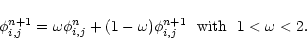
2.2.5 Time integration
One requirement in a coupled N-body and hydrodynamical code is the
possibility to deal with variable time steps. The stability conditions
for the time step is indeed given by the Courant Friedrich Levy (CFL)
condition, which can vary in time. The standard leapfrog scheme
(Hockney & Eastwood 1981), though accurate, does not offer this possibility.
In RAMSES, a second-order midpoint scheme has been implemented, which
reduces exactly to the second order leapfrog scheme for constant time
steps. Since the acceleration
 is known at time
tn from particle positions
is known at time
tn from particle positions
 ,
positions and velocities
are updated first by a predictor step
,
positions and velocities
are updated first by a predictor step
 |
|
|
(5) |
 |
|
|
(6) |
and then by a corrector step
 |
|
|
(7) |
In this last equation, the acceleration at time tn+1 is
needed. In order to avoid an extra call to the Poisson solver, this
last operation is postponed to the next time step. The new velocity is
computed as soon as the new potential is obtained. In RAMSES, it is
possible to have either a single time step for all particles, or
individual time steps for each level. In the latter case, when a
particle exits level
with time step
 ,
the
corrector step is applied at level ,
using
in place of
,
the
corrector step is applied at level ,
using
in place of
 .
Therefore, the "past history'' of
all particles has to be known in order to apply correctly the
corrector step. This is done in RAMSES by introducing one extra
integer per particle indicating its current level. This particle
"color'' is eventually modified at the end of the corrector step.
.
Therefore, the "past history'' of
all particles has to be known in order to apply correctly the
corrector step. This is done in RAMSES by introducing one extra
integer per particle indicating its current level. This particle
"color'' is eventually modified at the end of the corrector step.
Usually, the time step evolution is smooth, making our
integration scheme second-order in time. However, if one uses the
adaptive time step scheme instead of the more accurate (but time
consuming) single time step scheme, the time step changes abruptly by
a factor of two for particles crossing a refinement boundary. Only
first order accuracy is retained along those particle trajectories.
This loss of accuracy has been analyzed in realistic cosmological
conditions (Kravtsov & Klypin 1999; Yahagi & Yoshii 2001) and turns out to have a small
effect on the particle distribution, when compared to the single time
step case.
2.3 Hydrodynamical solver
In RAMSES, the Euler equations are solved in their conservative form:
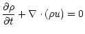 |
|
|
(8) |
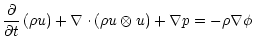 |
|
|
(9) |
![$\displaystyle \frac{\partial}{\partial t} \left( \rho {\rm e} \right) +
\nabla ...
...\rho {u} \left( {\rm e} + p/\rho \right) \right]
= - \rho {u} \cdot \nabla \phi$](/articles/aa/full/2002/13/aa1593/img56.gif) |
|
|
(10) |
where
is the mass density, u is the fluid velocity, e
is the specific total energy, and p is the thermal pressure, with
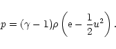 |
(11) |
Note that the energy equation (Eq. (10)) is conservative
for the total fluid energy, if one ignores the source terms due to
gravity. This property is one of the main advantages of solving the
Euler equations in conservative form: no energy sink due to numerical
errors can alter the flow dynamics. Gravity is included in the system
of equation as a non stiff source term. In this case, the system
is not explicitly conservative and the total energy (potential +
kinetic) is conserved at the percent level (see Sect. 4.3).
Let Uni denote a numerical approximation to the cell-averaged
value of
 at time tn and for cell
i. The numerical discretization of the Euler equations with
gravitational source terms writes:
at time tn and for cell
i. The numerical discretization of the Euler equations with
gravitational source terms writes:
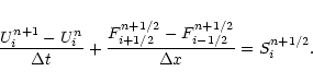 |
(12) |
The time centered fluxes
Fn+1/2i+1/2 across cell interfaces
are computed using a second-order Godunov method (also known as
Pieceweise Linear Method), with or without directional splitting
(according to the user's choice), while gravitational source terms
are included using a time centered, fractional step approach:
| |
|
Sn+1/2i = |
|
| |
|
 |
(13) |
A general description of Godunov and fractional step methods can be
found in Toro (1997). The present implementation is based on the
work of Collela (1990) and Saltzman (1994). For sake of
brevity, only its basic features are recalled here.
In this section, I describe the basic hydrodynamical scheme used in
RAMSES to solve Eqs. (8-10) at a given
level. It is assumed that proper boundary conditions have been
provided: the hydrodynamical scheme requires 2 ghost zones in each
side and in each direction, even in the diagonal directions. Since in
RAMSES the Euler equations are solved on octs of
cells
each,
similar neighboring octs are required to define
proper boundary conditions. The basic stencil of the PLM scheme
therefore contains
 cells. This is not the case for PPM
(Collela & Woodward 1984) for which 4 ghost zones are required in each side
and in each direction. Since the AMR structure in RAMSES is based on
octs (
cells), PPM would be to expensive to implement in
many aspects. One solution would be to modify the basic tree element
and increase the number of cells per oct from
cells to
cells. This is not the case for PPM
(Collela & Woodward 1984) for which 4 ghost zones are required in each side
and in each direction. Since the AMR structure in RAMSES is based on
octs (
cells), PPM would be to expensive to implement in
many aspects. One solution would be to modify the basic tree element
and increase the number of cells per oct from
cells to
 cells. The resulting AMR structure would however loose
part of its flexibility to adapt itself to complex flow geometry. The
FLASH code Fryxell et al. (2000) is an example of such an implementation,
using the PPM scheme in a similar recursive tree structure, with
however
cells. The resulting AMR structure would however loose
part of its flexibility to adapt itself to complex flow geometry. The
FLASH code Fryxell et al. (2000) is an example of such an implementation,
using the PPM scheme in a similar recursive tree structure, with
however
 cells per basic tree element.
For a given time step, we need to compute second-order, time-centered
fluxes at cell interfaces. This is done in RAMSES using a Riemann
solver, with left and right states obtained by a characteristics
tracing step. A standard characteristic analysis is done first,
by Taylor expanding the wave equations to second order and projecting
out the waves that cannot reach the interface within the time
step. These states are then adjusted to account for the gravitational
field. If the chosen scheme is not directionally split, transverse
derivative terms are finally added to account for transverse fluxes
(Saltzman 1994). The slopes that enter into the Taylor expansion
are computed using the Min-Mod limiter to ensure the monotonicity of
the solution.
The Riemann solver used to compute the Godunov states is "almost
exact'', in the sense that a correct pressure at the contact
discontinuity is obtained iteratively (typically, for strong shocks 10
Newton-Raphson iterations are required for single-precision
accuracy of 10-7). The only approximation relies in the
assumption that the rarefaction wave has a linear profile. In the
final step, fluxes of the conserved variables are computed using these
Godunov states. The outputs of the single grid algorithm are therefore
fluxes across cell interfaces.
Practically, this single grid module is applied to a large vector of
stencils of
cells each. For a large Cartesian grid of
 cells, the CPU time overhead associated to this solution
is rather large. Since the main time consuming part is the Riemann
solver, the estimated CPU time overhead was found to be roughly 50%,
100% and 200% for
cells, the CPU time overhead associated to this solution
is rather large. Since the main time consuming part is the Riemann
solver, the estimated CPU time overhead was found to be roughly 50%,
100% and 200% for
 ,
2 and 3 respectively. Since in any
useful AMR calculation, the mesh structure is not a regular Cartesian
grid, the actual overhead is much lower, although difficult to
estimate in practice. Moreover, this solution is much easier to
implement than any potentially faster alternative one can think of,
and easy to optimize on vector and parallel supercomputers.
,
2 and 3 respectively. Since in any
useful AMR calculation, the mesh structure is not a regular Cartesian
grid, the actual overhead is much lower, although difficult to
estimate in practice. Moreover, this solution is much easier to
implement than any potentially faster alternative one can think of,
and easy to optimize on vector and parallel supercomputers.
2.3.2 AMR implementation
This section describes how the solution is advanced in time within the
present AMR methodology. Note that this procedure is recursive with
respect to level
(step 3).
- 1.
- Generate new refinements at level
by
conservative interpolation of level
variables;
- 2.
- Compute the new time step
using the CFL
Courant condition and the constraint
 ;
;
- 3.
- Advance the solution in time for level ,
once in the single
time step case, or twice for the adaptive time step case;
- 4.
- Modify the time step
according to the
synchronisation constraint
 for the single time step case or
for the adaptive time step case;
for the single time step case or
for the adaptive time step case;
- 5.
- Compute boundary conditions in a temporary buffer
by conservative interpolation of level
variables;
- 6.
- Compute fluxes using the single grid Godunov solver;
- 7.
- Replace the fluxes at coarse-fine interface by averaging the fluxes
computed at level ;
- 8.
- For leaf cells, update variables using these fluxes;
- 9.
- For split cells, update variables by averaging down the updated variables
of level ;
- 10.
- Build the new refinement map.
In RAMSES, boundary conditions are supplied to fine levels by a
conservative linear reconstruction of coarse cell values (step 5). The
actual interpolation scheme is a 3D generalization of the Min-Mod
limiter (De Zeeuw 1993). The coarse solution is assumed to remain
constant in time during the advance of the fine solution. For fine
cells at coarse-fine boundaries and for the adaptive time step case
only, the accuracy reduces thus from second to first order in time,
but the global solution remains second order (Khokhlov 1998).
The time step is determined for each level independently, using
standard stability constraints for both N-body and hydrodynamical
solvers.
The first constraint comes from the gravitational evolution of the
coupled N-body and hydrodynamical system, imposing that
 should be smaller than a fraction C1<1 of the minimum
free-fall time
should be smaller than a fraction C1<1 of the minimum
free-fall time
 |
(14) |
An additional constraint comes from particle dynamics within the AMR
grid, imposing that particles move by only a fraction C2<1 of the
local cell size.
 |
(15) |
A third constraint is imposed on the time step by specifying that the
expansion factor
 should not vary more than
 over one time step. This constraint is active only at early
times, during the linear regime of gravitational clustering.
over one time step. This constraint is active only at early
times, during the linear regime of gravitational clustering.
 |
(16) |
The last constraint is imposed by the Courant Friedrich Levy stability
condition, which states that the time step should be smaller than
 |
(17) |
where cfl < 1 is the Courant factor. In the coupled N-body and
hydrodynamics case, the actual time step is equal to
 .
.
2.5 Refinement strategy
The refinement strategy is the key issue for any AMR calculation.
Bearing in mind that the overhead associated to the AMR scheme can be
as large as a factor of 2 to 3 (see Sect. 2.3)
compared to the corresponding uniform grid algorithm, the maximum
fraction of the grid that can be refined lies in between 30% to 50%.
One should therefore design a refinement strategy that allows for an
accurate treatment of the underlying physical problem, but minimizes
also the fraction of the volume to be refined.
For the N-body solver, the refinement strategy is based on the
so-called "quasi-Lagrangian'' approach. As in Kravtsov et al. (1997),
the idea is to obtain a constant number of particles per cell. In
this way, two-body relaxation effects can be minimized, as well as the
Poisson noise due to particle discreteness effects. The latter effect
can be damaging when coupling the N-body code to the
hydrodynamics solver. The "quasi-Lagrangian'' approach is
implemented by refining cells at level
if the dark matter
density exceeds a level dependent density threshold, defined as
 |
(18) |
where  is the maximum mass (or number of particles) per cell.
For pure N-body simulations,
is usually chosen around 5-10
particles (Kravtsov et al. 1997), which gives a few particles per cell on
average. For gas dynamics simulations,
should be chosen around
40-80 particles, in order to lower enough the Poisson noise. In this
case, we obtain indeed more than 10 particles per cell on
average. Note also that since for gas dynamics simulations, the total
memory is dominated by the storage associated to the fluid variables,
the number of particles par cell can be chosen much higher than for
pure dark matter simulations.
is the maximum mass (or number of particles) per cell.
For pure N-body simulations,
is usually chosen around 5-10
particles (Kravtsov et al. 1997), which gives a few particles per cell on
average. For gas dynamics simulations,
should be chosen around
40-80 particles, in order to lower enough the Poisson noise. In this
case, we obtain indeed more than 10 particles per cell on
average. Note also that since for gas dynamics simulations, the total
memory is dominated by the storage associated to the fluid variables,
the number of particles par cell can be chosen much higher than for
pure dark matter simulations.
As for the N-body solver, a "quasi-Lagrangian'' approach can be
implemented for the gas component, using level dependent density
thresholds defined by
 |
(19) |
In order to follow the same Lagrangian evolution than the dark matter
component, the typical baryonic mass per cell  can be derived as
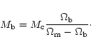 |
(20) |
For pure gas dynamics applications, other refinement criteria can be
used (see Khokhlov 1998 for more examples). In RAMSES, only
refinement criteria based on gradients of the flow variables have been
implemented: for each cell i and for any relevant flow variable q(pressure, density, Mach number...), its gradient is computed using the
neighboring cells. If this gradient, times the
local mesh spacing, exceeds a fraction of the central cell variable
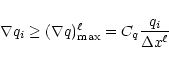 |
(21) |
then cell i is refined. The parameter Cq is a free parameter
that need to be specified by the user. A similar criterion based
on second derivatives of the flow variables has also been
implemented.
The last refinement criterion implemented in RAMSES is purely spatial:
for each level, refinements are not allowed outside a sphere centered
on the box center. This last criterion allows the user to refine the
computational mesh only in the center of the box, in order to follow
properly the formation of a single structure, without spending to much
resources in refining also the surrounding large scale field. The
radius of this spherical region, noted
 ,
can be specified
for each level independently.
,
can be specified
for each level independently.
2.6 Cosmological settings
RAMSES can be used for standard fluid dynamics or N-body problems,
with periodic, reflecting, inflow or outflow boundary conditions. For
the present paper, RAMSES is however used in the cosmological context.
The N-body solver and the hydrodynamics solver are both implemented
using "conformal time'' as the time variable. This allows a
straightforward implementation of comoving coordinates, with minor
changes to the original equations. The details of these so-called
"super-comoving coordinates'' can be found in Martel & Shapiro (1998) and
references therein. The idea is to perform the following change of
variables
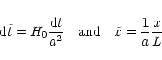 |
(22) |
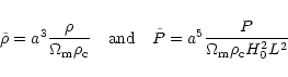 |
(23) |
 |
(24) |
where H0 is the Hubble constant,
 is the matter density
parameter, L is the box size and
is the matter density
parameter, L is the box size and
 is the critical density.
In the specific case
is the critical density.
In the specific case
 ,
Eqs. (1) and (8-10)
remain unchanged, at the exception of the
Poisson equation which now reads
,
Eqs. (1) and (8-10)
remain unchanged, at the exception of the
Poisson equation which now reads
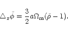 |
(25) |
If
 ,
a single additional source term must be included
in the right-hand side of the energy conservation equation
(Eq. (10)). These "super-comoving coordinates'' simplify
greatly the introduction of comoving variables in the equations.
,
a single additional source term must be included
in the right-hand side of the energy conservation equation
(Eq. (10)). These "super-comoving coordinates'' simplify
greatly the introduction of comoving variables in the equations.
![\begin{figure}
\par\includegraphics[width=16.6cm]{aa1593f1.ps}\end{figure}](/articles/aa/full/2002/13/aa1593/Timg90.gif) |
Figure 1:
Acceleration of massless test particles dropped randomly around single
massive particles, whose positions are also chosen randomly in the
box. The coarse grid has 323 cells. The number of refinement levels
is progressively increased from 0 to 6, with increased spatial
resolution around the massive particles. The radial AMR acceleration
divided by the true acceleration is shown as light grey dots (versus
radius in units of coarse cell size). The same ratio for the
tangential AMR acceleration is shown as dark grey dots. The force
corresponding to an homogeneous sphere with radius equal to the
smallest cell length is also plotted for comparison (solid line). |
| Open with DEXTER |
3 Tests of the code
In this section, I present tests of increasing complexity for both the
N-body solver and the hydrodynamical solver. These tests are also
useful to choose the correct parameters for realistic cosmological
applications described in the last section.
Particles of unit mass are placed randomly in the computational
box, whose coarse grid is defined by
nx = ny
= nz=32. Test particles are then dropped randomly in
order to sample the acceleration around each massive particle. The
AMR grid is built around each central particle. For that purpose,
refinement density thresholds were set to
 for each
level. An increasing number of refinement levels was used, from
for each
level. An increasing number of refinement levels was used, from
 to
to
 ,
the latter case
corresponding to a formal resolution of 20483. Mesh smoothing was
performed with
,
the latter case
corresponding to a formal resolution of 20483. Mesh smoothing was
performed with
 .
.
Figure 1 shows the resulting radial and tangential
accelerations, divided by the true 1/r2 force. The tangential
acceleration gives here an indication of the level of force anisotropy
and accuracy. Note that the acceleration due to the ghost images of
the massive particle (periodic boundary conditions) was substracted
from the computed acceleration (using the Ewald summation method).
For comparison, the acceleration of an homogeneous sphere (with radius
equal to the cell size of the maximum refinement level) is also
plotted in Fig. 1 as a solid line: the AMR acceleration
appears to provide a slightly lower spatial resolution (rouhly 1.5
cell size). At lower radius, the force smoothly goes to zero, exactly
as for a PM code of equivalent dynamical range. At lower radius, the
force anisotropy is also the same as for a PM code of equivalent
dynamical range. On the other hand, at higher radius, the force
anisotropy remains close to 1%. Contrary to a single grid PM
solver, the force error does not decrease monotonically as radius
increases. Here, the error level remains roughly constant (at the
percent level), since the spatial resolution also decreases as radius
increases. In fact, the AMR force on a given particle corresponds to a
single grid PM force whose cell size is equal to that of the
particle's current level. As one goes from one level to the next,
discontinuities in the force remain also at the percent level.
![\begin{figure}
\par\includegraphics[width=16.6cm]{aa1593f2.ps}\end{figure}](/articles/aa/full/2002/13/aa1593/Timg95.gif) |
Figure 2:
Particle positions obtained in a CDM simulation are
considered in this test. Each panel shows the force error for
particles sitting at different levels of refinement. The error is
defined as the difference between the AMR force and the force computed
by a PM code of equivalent spatial resolution. In each panel, the
average and the variance of the error are also shown. |
| Open with DEXTER |
In order to assess the quality of the gravitational acceleration
computed by RAMSES in a cosmological situation, we consider now a set
of 643 particles obtained in a CDM simulation, at redshift
z=0. In this way, we are able to quantify the force errors in a
typical hierarchical clustering configuration, with the corresponding
mesh refinements structure. The coarse grid was defined by
nx=ny=nz=32 and each particle
was assigned a mass
 .
The adaptive mesh was built using
refinement density thresholds
.
The adaptive mesh was built using
refinement density thresholds
 for each
level .
Each cell is therefore refined if it contains more than
40 particles, with a roughly constant number of particles per cell
after each refinement (between 5 and 40). Mesh structures associated
to this particle distribution are shown in the last section of the
paper (Fig. 10).
for each
level .
Each cell is therefore refined if it contains more than
40 particles, with a roughly constant number of particles per cell
after each refinement (between 5 and 40). Mesh structures associated
to this particle distribution are shown in the last section of the
paper (Fig. 10).
For each level of refinement, the AMR force is then compared to the PM
force of equivalent spatial resolution (see Fig. 2). For
particles sitting at the coarse level (), the force is by
construction exactly equal to the PM force with 323 cells (results
not shown in the figure). For levels ,
,
 and
and
 ,
the AMR force is compared to the PM force with respectively
643, 1283, 2563 and 5123 cells. In Fig. 2, each
panel shows the difference between the AMR force and the PM force for
each level. The number of particles sitting at each level is indicated
in the upper-left part of each panel. The mean force error and the
standard deviation is indicated in the lower-left part of each
panel. Although the error distribution is strongly non Gaussian, its
typical magnitude remains at the percent level in all cases. Note
that errors are larger for forces of intermediate and small values,
indicating that those particles might be sensitive to the boundary
conditions (tidal field) imposed on the level boundaries (this is the
main source of inaccuracy in the N-body scheme). On the other hand,
for particles with strong acceleration, the AMR force is almost
indistinguishable from the PM force of equivalent resolution.
,
the AMR force is compared to the PM force with respectively
643, 1283, 2563 and 5123 cells. In Fig. 2, each
panel shows the difference between the AMR force and the PM force for
each level. The number of particles sitting at each level is indicated
in the upper-left part of each panel. The mean force error and the
standard deviation is indicated in the lower-left part of each
panel. Although the error distribution is strongly non Gaussian, its
typical magnitude remains at the percent level in all cases. Note
that errors are larger for forces of intermediate and small values,
indicating that those particles might be sensitive to the boundary
conditions (tidal field) imposed on the level boundaries (this is the
main source of inaccuracy in the N-body scheme). On the other hand,
for particles with strong acceleration, the AMR force is almost
indistinguishable from the PM force of equivalent resolution.
![\begin{figure}
\par\includegraphics[width=16.1cm]{aa1593f3.ps}\end{figure}](/articles/aa/full/2002/13/aa1593/Timg100.gif) |
Figure 3:
Shock Tube Test: density, velocity, pressure and refinement level as a
function of position at time t=0.245. Numerical results are shown as
squares, and compared to the analytical solutions (solid lines). See
text for details. |
| Open with DEXTER |
The initial conditions are defined by a left state given by
 ,
,
 and
and
 and by a right state given by
 ,
,
 and
and
 for a
for a
 fluid. This
test (also called Sod's test) is interesting because it captures all
essential features of one dimensional hydrodynamical flows, namely a
shock wave, a contact discontinuity and a rarefaction wave. While the
latter wave remains continuous, the 2 former features are
discontinuous. Modern shocks capturing methods like the one used in
RAMSES spread shock fronts over 2 to 3 zones. Contact discontinuities
are usually more difficult to capture (say 6 to 10 cells), and the
spreading usually increases with the number of time step.
This
numerical smoothing is responsible for the dissipation of the scheme.
AMR technique allows one to increase the spatial resolution around the
discontinuities and therefore to minimize the numerical dissipation.
In the present application, the refinement criteria are based on
pressure, density and Mach number gradients (see
Sect. 2.5), with parameter
fluid. This
test (also called Sod's test) is interesting because it captures all
essential features of one dimensional hydrodynamical flows, namely a
shock wave, a contact discontinuity and a rarefaction wave. While the
latter wave remains continuous, the 2 former features are
discontinuous. Modern shocks capturing methods like the one used in
RAMSES spread shock fronts over 2 to 3 zones. Contact discontinuities
are usually more difficult to capture (say 6 to 10 cells), and the
spreading usually increases with the number of time step.
This
numerical smoothing is responsible for the dissipation of the scheme.
AMR technique allows one to increase the spatial resolution around the
discontinuities and therefore to minimize the numerical dissipation.
In the present application, the refinement criteria are based on
pressure, density and Mach number gradients (see
Sect. 2.5), with parameter
 .
The maximum number of refinements was set to
,
for a coarse level mesh size nx=64. Mesh
smoothing (see Sect. 2.1.1) is performed using
.
Note that the refined mesh is built before the beginning
of the simulation. The time step is controlled by a Courant number
cfl=0.8. Results are shown at time t=0.245 and compared to the
analytical solution in Fig. 3. The shock front and the
contact surface are refined up to the maximum refinement level: the
formal resolution is therefore 4096. The total number of cells
(counting both split and leaf cells) is only 560, or 14% of the
corresponding uniform mesh size. 69 time steps were necessary at the
coarse level, while 4416 time steps were necessary at level
.
The maximum number of refinements was set to
,
for a coarse level mesh size nx=64. Mesh
smoothing (see Sect. 2.1.1) is performed using
.
Note that the refined mesh is built before the beginning
of the simulation. The time step is controlled by a Courant number
cfl=0.8. Results are shown at time t=0.245 and compared to the
analytical solution in Fig. 3. The shock front and the
contact surface are refined up to the maximum refinement level: the
formal resolution is therefore 4096. The total number of cells
(counting both split and leaf cells) is only 560, or 14% of the
corresponding uniform mesh size. 69 time steps were necessary at the
coarse level, while 4416 time steps were necessary at level  .
It is worth mentioning that pressure and velocity remain remarkably
uniform across the contact discontinuity, and no side effects due to
the presence of discrete refinement ratio are noticeable.
.
It is worth mentioning that pressure and velocity remain remarkably
uniform across the contact discontinuity, and no side effects due to
the presence of discrete refinement ratio are noticeable.
![\begin{figure}
\par\includegraphics[width=16.2cm]{aa1593f4.ps}\end{figure}](/articles/aa/full/2002/13/aa1593/Timg110.gif) |
Figure 4:
Planar Sedov Blast Wave Test: density, velocity, pressure and
refinement level as a function of position for times t=0.05, 0.1,
0.15, 0.2, 0.25 and 0.3. Numerical results are shown as squares, and
compared to the analytical solutions (solid lines). See text for
details. |
| Open with DEXTER |
The last test, though interesting and complete, is not a very
stringent one, since it involves a rather weak shock. In order to test
the ability of RAMSES to handle strong shocks (a common feature in
cosmology), let us consider the planar Sedov problem: the
computational domain is filled with a
fluid with
 ,
u0=0 and
P0=10-5. A total (internal) energy
E0=1/2 is deposited in the first cell only at x=0+. Note that
here again the refined mesh is built before the beginning of the
simulation. Reflexive boundary conditions are considered. The grid is
defined by nx=32 with 6 levels of refinement. The only refinement
criterion used here is based on pressure gradients, with
,
u0=0 and
P0=10-5. A total (internal) energy
E0=1/2 is deposited in the first cell only at x=0+. Note that
here again the refined mesh is built before the beginning of the
simulation. Reflexive boundary conditions are considered. The grid is
defined by nx=32 with 6 levels of refinement. The only refinement
criterion used here is based on pressure gradients, with
 .
Mesh smoothing is guaranteed by
.
The
Courant number is set to cfl=0.8. Very rapidly, a self-similar flow
builds up, following the analytical solution described in
Sedov (1993). Simulation results are shown for different output
times and compared to the analytical solutions. Note that the shock
front propagates exactly at the correct speed. The numerical solution
closely matches the analytical one, without any visible post-shock
oscillations. 239 time steps only were necessary at the coarse level,
but 15296 time steps were necessary at the finest refinement level.
The total number of cells (including split cells) in the adaptive mesh
structure is only 130, to be compared with 2048 cells for the uniform
grid of equivalent spatial resolution (4.3%). Due to the refinement
criterion used here, the adaptive mesh mainly concentrates the
computational effort around the shock front. In one dimension, as it
is the case here, discontinuities like shocks are quite inexpensive to
deal with: if one adds one level of refinement, the total number of
cells increases by a constant (and small) amount. For two- and
three-dimensional calculations, the situation is much more demanding:
since shocks and contacts discontinuities are surface waves,
increasing the resolution by a factor of 2 corresponds to increasing
the total number of cells by a factor of 2 for
.
Mesh smoothing is guaranteed by
.
The
Courant number is set to cfl=0.8. Very rapidly, a self-similar flow
builds up, following the analytical solution described in
Sedov (1993). Simulation results are shown for different output
times and compared to the analytical solutions. Note that the shock
front propagates exactly at the correct speed. The numerical solution
closely matches the analytical one, without any visible post-shock
oscillations. 239 time steps only were necessary at the coarse level,
but 15296 time steps were necessary at the finest refinement level.
The total number of cells (including split cells) in the adaptive mesh
structure is only 130, to be compared with 2048 cells for the uniform
grid of equivalent spatial resolution (4.3%). Due to the refinement
criterion used here, the adaptive mesh mainly concentrates the
computational effort around the shock front. In one dimension, as it
is the case here, discontinuities like shocks are quite inexpensive to
deal with: if one adds one level of refinement, the total number of
cells increases by a constant (and small) amount. For two- and
three-dimensional calculations, the situation is much more demanding:
since shocks and contacts discontinuities are surface waves,
increasing the resolution by a factor of 2 corresponds to increasing
the total number of cells by a factor of 2 for
 and 4 for
.
Therefore, we have to face the possibility of stopping
at some level the refinement hierarchy and investigate what happens to
the numerical solution in this case.
and 4 for
.
Therefore, we have to face the possibility of stopping
at some level the refinement hierarchy and investigate what happens to
the numerical solution in this case.
3.5 Strong shock passing through a Coarse-Fine interface
![\begin{figure}
\par\includegraphics[width=12.6cm,clip]{aa1593f5.ps}\end{figure}](/articles/aa/full/2002/13/aa1593/Timg114.gif) |
Figure 5:
Strong shock passing through a Coarse-Fine interface with Mach number
M=5000 and
,
computed with cfl=0.5. The upper plot
shows the reference case with a 256 cells coarse grid, uniformly
refined up to level
(without any coarse-fine boundary). The
middle figure shows the case where the shock goes through a
fine-to-coarse boundary (located around
 ), while the
bottom figure shows the case where the shock goes to a
coarse-to-fine boundary (located around the same place). In the
latter case, perturbations of the order of 5% are generated in the
post-shock flow. ), while the
bottom figure shows the case where the shock goes to a
coarse-to-fine boundary (located around the same place). In the
latter case, perturbations of the order of 5% are generated in the
post-shock flow. |
| Open with DEXTER |
It is well known that in any AMR calculations, discontinuities in the
flow (like the one discussed in the previous sections) must be refined
up to the maximum level, in order to obtain accurate results
(Berger & Collela 1989; Khokhlov 1998). Unfortunately, it is not always possible
to satisfy this rule because of memory limitations, even on modern
computers. One has therefore to consider cases for which
discontinuities leave or enter regions of different spatial
resolution. The situation is especially sensitive for contact
surfaces, since as soon as the code spreads them over, say, 6 cells,
no matter how much one refines them afterwards, they will preserve
their original thickness. Shock waves, however, have a self-steepening
mechanism that allows them to adapt to the local resolution and
restore their sharp profile over 2 to 3 cells only. The price to pay
for this interesting property is the appearance of post-shock
oscillations after the front has entered a high-resolution region. To
illustrate this, Khokhlov (1998) proposed a simple test based on
the propagation of a strong shock wave across a coarse-fine
interface. Khokhlov's test is reproduced here using the following
parameters: the shock Mach number is set to M=5000 with
.
The base grid resolution is set to nx=256 and the
Courant number is set to cfl=0.5.
The following three cases have been considered:
- 1.
- the whole computational domain is refined up to ;
- 2.
- the computational domain is refined up to
only left to
x=234;
- 3.
- the computational domain is refined up to
right to
x=234 and up to
otherwise.
The resulting density profiles are shown in Fig. 5. While
in the 2 former cases, the density profiles show no visible
oscillations, the latter case does show small oscillations of the
order of 5%. This is a direct consequence of the abrupt change of
spatial resolution between the 2 levels of refinement (see the discussion in 1989). To summarize, if shock waves move from
high- to low-resolution regions, spurious effects associated to the
mesh structure are undetectable. This is not the case in the opposite
situation, which causes spurious (though small) post-shock
oscillations. Note however that for weak shocks the effect is
undetectable (Berger & Collela 1989). In cosmology, it is worth mentioning
that, since the basic features are accretion shocks, we are always in
a favorable situation: strong shocks originate in high-density
(high-resolution) regions, and propagates outwards, in a low-density
(low-resolution) background. To my opinion, this fundamental property
allows us to use safely adaptive mesh technique in cosmological
simulations.
![\begin{figure}
\par\includegraphics[width=16.1cm]{aa1593f6.ps}\end{figure}](/articles/aa/full/2002/13/aa1593/Timg115.gif) |
Figure 6:
Spherical Sedov blast wave test: rescaled density, velocity, pressure
and volume-averaged refinement level as a function of radius for times
t=10-4,
 and
and
 .
Numerical
results (solid lines with error bars) are compared to the
analytical solutions (solid lines). See text for details. .
Numerical
results (solid lines with error bars) are compared to the
analytical solutions (solid lines). See text for details. |
| Open with DEXTER |
We now consider a very difficult test for Cartesian grids like the one
used in RAMSES: the spherical Sedov test. In contrary to the planar,
1D case, the spherical blast wave is now fully three-dimensional and
pretty far from the natural geometry of the code. Moreover, as stated
before, shock waves in 3D are essentially two-dimensional: the total
number of cells necessary to cover the shock front scales with spatial
resolution as
 |
(26) |
where  is the curvature radius of the shock. For
,
one clearly sees that the number of required cells quickly
explodes. On the other hand, for the Sedov blast wave test, it is more
interesting to keep the relative thickness of the shock low
enough to capture the true solution. As we have seen in the last
section, if one degrades the resolution as the shock propagates
outwards, no spurious effects are expected. In RAMSES, we can enforce
a position-dependent spatial resolution by forbidding a given level
of refinement to be activated if the radius of the cell is larger than
a given threshold (see Sect. 2.5). The run
parameters are therefore the followings: the coarse grid size is set
to
nx=ny=nz=32 and the maximum level of refinement is chosen to
be
.
The maximum refinement radius for each level is
given by
is the curvature radius of the shock. For
,
one clearly sees that the number of required cells quickly
explodes. On the other hand, for the Sedov blast wave test, it is more
interesting to keep the relative thickness of the shock low
enough to capture the true solution. As we have seen in the last
section, if one degrades the resolution as the shock propagates
outwards, no spurious effects are expected. In RAMSES, we can enforce
a position-dependent spatial resolution by forbidding a given level
of refinement to be activated if the radius of the cell is larger than
a given threshold (see Sect. 2.5). The run
parameters are therefore the followings: the coarse grid size is set
to
nx=ny=nz=32 and the maximum level of refinement is chosen to
be
.
The maximum refinement radius for each level is
given by
 |
(27) |
We use refinement criteria based on pressure gradients with CP=0.5and mesh smoothing parameter
.
The fluid is
supposed initially at rest with
and
P0=10-5. A total
(internal) energy E0=1 is deposited in the 8 central cells
only. The refined mesh is here again built before the beginning of the
time integration. We assume cfl=0.8 and
.
We use here a
single time step for all levels, since in this particular case, this
is the fastest solution.
Results are shown in Fig. 6 and compared to the analytical
solutions of Sedov (1993) for 3 different output times. Each
quantity represents a volume-average value over spherical bins, whose
thicknesses correspond to the local resolution. Each quantity was also
rescaled according to the (time-dependent) analytical post-shock
values (labeled with an "s'') for sake of visibility. Error
bars are computed using the standard deviation of the numerical
solution from the mean value in each spherical bin. The agreement
with the analytical solution is remarkable, considering that the mesh
has a Cartesian geometry. The main departure is found in the velocity
profile at a radius around 60% of the shock radius. Similar results
were obtained by Fryxell et al. (2000). An easy way of solving this
problem would be to lower the pressure gradients threshold  ,
which would directly increase the resolution in this region, at the
expense of increasing the total number of cells. Oscillations due to
spurious mesh reflections are not visible in the radial profiles.
Direct inspection of the 3D data shows that the only systematic effect
is the departure from spherical symmetry due to the Cartesian nature
of the mesh. In Fig. 6, the volume-averaged refinement
level is shown as a function of radius for different times. Due to
the maximum refinement radii we used (Eq. (27)), the adaptive
mesh evolution is also self-similar, though in a piecewise constant
manner. The total number of cells (and therefore the memory used)
remains roughly constant over the calculation (around 106 cells,
including split cells). The interest of using a tree-based approach
for building the adaptive mesh appears clearly in this test, since the
mesh structure follows as closely as possible the spherical shape of
the shock front.
,
which would directly increase the resolution in this region, at the
expense of increasing the total number of cells. Oscillations due to
spurious mesh reflections are not visible in the radial profiles.
Direct inspection of the 3D data shows that the only systematic effect
is the departure from spherical symmetry due to the Cartesian nature
of the mesh. In Fig. 6, the volume-averaged refinement
level is shown as a function of radius for different times. Due to
the maximum refinement radii we used (Eq. (27)), the adaptive
mesh evolution is also self-similar, though in a piecewise constant
manner. The total number of cells (and therefore the memory used)
remains roughly constant over the calculation (around 106 cells,
including split cells). The interest of using a tree-based approach
for building the adaptive mesh appears clearly in this test, since the
mesh structure follows as closely as possible the spherical shape of
the shock front.
![\begin{figure}
\par\includegraphics[width=16.6cm]{aa1593f7.ps}\end{figure}](/articles/aa/full/2002/13/aa1593/Timg120.gif) |
Figure 7:
Zel'dovich Pancake Test: density, velocity, pressure and refinement
level as a function of position from the pancake mid-plane at z=0.
The solid line shows AMR results if refinements are activated using
both density thresholds and pressure gradients. This explains why the
2 accretion shocks are refined. The squares show AMR results if
refinements are activated using only density thresholds. See text for
details. |
| Open with DEXTER |
In this section, typical conditions encountered in cosmological
simulations are addressed using the Zel'dovich pancake test. This test
is widely used to benchmark cosmological hydrodynamics codes
(Cen 1992; Ryu et al. 1993; Bryan & Norman 1997; Teyssier et al. 1998), since it encompasses all
the relevant physics (gravity, hydrodynamics and expansion). It can be
thought as a single mode analysis of the collapse of random density
perturbations, a first step towards the study of the fully
three-dimensional case. The initial conditions are defined for a given
starting redshift  in an Einstein-de Sitter universe
(
in an Einstein-de Sitter universe
(
 ,
,
 ), using a sinusoidal density
perturbation of unit wavelength, i.e. of the form
), using a sinusoidal density
perturbation of unit wavelength, i.e. of the form
 |
(28) |
where x is the comoving distance to the pancake mid-plane (from now
on, we always use super-comoving coordinates, as defined in
Sect. 2.6). The initial velocity field is set according
to the linear theory of gravitational instability
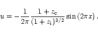 |
(29) |
The collapse redshift is chosen to be
 and the initial
redshift is
and the initial
redshift is
 .
The initial baryons temperature was set to a
very low arbitrary value, consistent with a negligible background
temperature.
.
The initial baryons temperature was set to a
very low arbitrary value, consistent with a negligible background
temperature.
The coarse grid is defined by nx=32. We use
 particles for
the dark matter component. The maximum level of refinement was set to
,
corresponding to a formal resolution of 2048. Two
different cases are investigated: in the first run, both pressure
gradients and gas density thresholds (quasi-Lagrangian mesh) are used
to build the adaptive mesh, with
particles for
the dark matter component. The maximum level of refinement was set to
,
corresponding to a formal resolution of 2048. Two
different cases are investigated: in the first run, both pressure
gradients and gas density thresholds (quasi-Lagrangian mesh) are used
to build the adaptive mesh, with
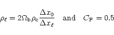 |
(30) |
while in the second case, only gas density thresholds are used to
trigger new refinements.
Results are shown in Fig. 7 for both cases. For the first
case, the two accretion shock fronts are refined up to the maximum
refinement level, and are therefore very sharp. For the second case,
however, the shock fronts are not refined at all. The shock waves are
traveling outwards, from the high-resolution region in the pancake
center, to the low-resolution background. In light of what have been
discussed in the previous sections, this explains why no oscillations
(due to potential spurious reflections at level boundaries) are
visible. It is worth mentioning that both sets of profiles are almost
indistinguishable in the center of the pancake. This last test is very
encouraging, since it allows us to avoid refining shock fronts in
cosmological simulations. The opposite situation would have been
dramatic, because of the large filling factor of cosmic shock waves
(especially in 3D), which would result in a very large memory
overhead, and because it would trigger collisionality in the dark
matter particles distribution.
3.8 Spherical secondary infall
![\begin{figure}
\par\includegraphics[width=16.4cm]{aa1593f8.ps}\end{figure}](/articles/aa/full/2002/13/aa1593/Timg130.gif) |
Figure 8:
Secondary Infall Test: rescaled density, velocity, pressure and
volume-averaged refinement level as a function of radius (in units of
coarse cells length) for expansion factors a=64ai, 512ai and
4096ai. Numerical results (solid lines with error bars) are
compared to the analytical solutions of Bertschinger (1985) (solid
lines). See text for details. |
| Open with DEXTER |
The last test, while interesting, is not very stringent, since it is
very close to the natural, Cartesian geometry of the code. An
analytical solution describing the fully non-linear collapse of
spherical density perturbations was found by Bertschinger (1985),
for both pure dark matter and pure baryons fluids. The initial
conditions defining the system are the followings: a completely
homogeneous Einstein-de Sitter universe (with
)
contains a
single mass perturbation
 at some initial epoch
t0. Surrounding this initial seed, shells of matter with increasing
radius starts expanding within the Hubble flow, but finally decouples
from the expansion at some "turn around'' time, and the corresponding
turn around proper radius, given by
at some initial epoch
t0. Surrounding this initial seed, shells of matter with increasing
radius starts expanding within the Hubble flow, but finally decouples
from the expansion at some "turn around'' time, and the corresponding
turn around proper radius, given by
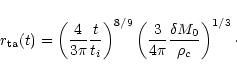 |
(31) |
Since in the problem, no other time- or length-scale are involved,
the overall evolution is self-similar.
In Kravtsov et al. (1997), the secondary infall test was successfully
passed by the ART code for the pure dark matter case. Results obtained
by RAMSES are very close to the ones obtained by the ART code, which
is reassuring, since both codes have almost the same N-body
solver. They are not presented here. Rather, we investigate the purely
baryonic self-similar infall, so as to validate the hydrodynamics
solver coupled to gravity and cosmological expansion.
The periodic box is initially filled with a critical density cold gas
with
.
A single dark matter particle with mass
is placed as initial seed in the center of the computational
domain. The coarse grid is defined by
nx=ny=nz=32 and the maximum
level of refinement was set to
 ,
providing us a
formal spatial resolution of 20483. Before the beginning of time
integration, the mesh is refined around the central seed using a
maximum refinement radius for each level given by
,
providing us a
formal spatial resolution of 20483. Before the beginning of time
integration, the mesh is refined around the central seed using a
maximum refinement radius for each level given by
 |
(32) |
in units of coarse cell size. The resulting mesh structure can be seen
in Fig. 8 in a volume-averaged radial representation, with
roughly 105 cells in the AMR tree, including split cells. No
pressure gradients criterion is used, so that shock fronts are not
refined. We use a Courant factor cfl=0.5. Starting at expansion
factor
ai=10-5, three output times were analyzed
(
 ,
512ai and 4096ai). The final epoch was reached
in 86 coarse time steps only, but 5504 time steps at the maximum level
of refinement.
,
512ai and 4096ai). The final epoch was reached
in 86 coarse time steps only, but 5504 time steps at the maximum level
of refinement.
The resulting rescaled density, pressure and velocity profiles
are plotted in Fig. 8 and compared to the analytical
solution of Bertschinger (1985). Error bars are computed using
the standard deviation of the numerical solution with respect to the
average radial value. The scaling relations for velocity, density and
pressure are obtained using their "turn around'' values
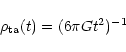 |
(33) |
 |
(34) |
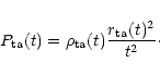 |
(35) |
We find a very good agreement between numerical and analytical
profiles, down to a radius of 2 fine cells, the actual resolution
limit of the code. As the shock propagates outwards, no spurious
reflection appears, as expected.
4 Application to cosmology: Structure formation in a
CDM universe
In this section, results obtained by RAMSES for a N-body and
hydrodynamical simulation of structure formation in a CDM
universe are reported. The box size was set to
 Mpc, as a good compromise between cosmic variance and resolution. The
influence of the chosen box size on the results are not investigated
in this paper. On the other hand, the convergence properties of the
solution are examined by varying the mass and spatial resolution using
6 different runs, whose parameters are listed in Table 1
below. Numerical results are also compared to analytical results
obtained in the framework of the halo model. This simple theory
predicts various quantities for both gas and dark matter
distributions, and has already proven to successfully reproduce
results obtained in various numerical simulations (see
Sect. 4.5). A careful comparison between the
analytical and the numerical approach will serve us as a guide to
investigate our understanding of structure formation in the universe.
Mpc, as a good compromise between cosmic variance and resolution. The
influence of the chosen box size on the results are not investigated
in this paper. On the other hand, the convergence properties of the
solution are examined by varying the mass and spatial resolution using
6 different runs, whose parameters are listed in Table 1
below. Numerical results are also compared to analytical results
obtained in the framework of the halo model. This simple theory
predicts various quantities for both gas and dark matter
distributions, and has already proven to successfully reproduce
results obtained in various numerical simulations (see
Sect. 4.5). A careful comparison between the
analytical and the numerical approach will serve us as a guide to
investigate our understanding of structure formation in the universe.
An initial Gaussian random field was generated for the highest
resolution run on a 2563 particle grid and (periodic) box length
 Mpc. The transfer function of Ma (1998) for a
flat CDM universe was used and normalized to the COBE data
(White & Bunn 1995), with the following cosmological parameters
Mpc. The transfer function of Ma (1998) for a
flat CDM universe was used and normalized to the COBE data
(White & Bunn 1995), with the following cosmological parameters
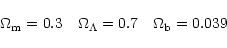 |
(36) |
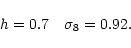 |
(37) |
The high resolution grid was then degraded twice (down to 1283 and
643) to provide consistent initial conditions for our low
resolution runs. In this way, a direct comparison between the 3
simulations is made possible. The corresponding mass resolution
(corresponding to individual particle masses for a pure dark matter
universe) is

 (
(
 and
and
 ). Particles were
initially displaced according to the Zel'dovich approximation up to a
starting redshift 1+zi=72 (51, 36) for the 2563 (1283,
643) grid. The initial gas density and velocity field was perturbed
according to the linear theory of gravitational clustering, using the
same density and displacement fields as for dark matter. The initial
gas temperature was set to
T = 548(1+zi)-2 K, in order to
recover the correct thermal history of baryons after recombination,
when neglecting re-ionization. The adiabatic index was set to
,
and a fully ionized, primordial
). Particles were
initially displaced according to the Zel'dovich approximation up to a
starting redshift 1+zi=72 (51, 36) for the 2563 (1283,
643) grid. The initial gas density and velocity field was perturbed
according to the linear theory of gravitational clustering, using the
same density and displacement fields as for dark matter. The initial
gas temperature was set to
T = 548(1+zi)-2 K, in order to
recover the correct thermal history of baryons after recombination,
when neglecting re-ionization. The adiabatic index was set to
,
and a fully ionized, primordial  and
and  plasma was considered, with mean molecular weight
 .
.
Table 1:
RAMSES parameters for our six CDM simulations. In each case,
the box size was set to L=100 h-1 Mpc.
|
|
The main ingredient in the cosmological simulations presented here is
the refinement strategy. In order to increase the spatial resolution
within collapsing regions, a quasi-Lagrangian mesh evolution was
naturally chosen, using level dependent dark matter and gas density
thresholds, as explained in Sect. 2.5. To be
more specific, the level dependent density thresholds for the dark
matter component were set to
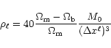 |
(38) |
while for the baryonic component, they were set to
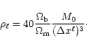 |
(39) |
In this way, a roughly constant number of particles per cell (between
5 and 40) is obtained, minimizing both collisionality and particle
discreteness effects. Note that this number is higher than the pure
dark matter simulations performed in Kravtsov et al. (1997), where 5
particles were used to trigger new refinements, instead of 40 in this
paper. As explained above, this choice has basically two reasons: 1-
we prefer to minimize as much as possible the effect of particle
discreteness effect (Poisson noise) on fluid dynamics, 2- since the
memory storage is dominated by fluid variables, we can increase the
number of particles per cell by one order of magnitude for a given
spatial resolution. The number 40 was finally retained to allow
for a simple comparison with the more standard refinement threshold of
Kravtsov et al. (1997), namely a factor of 2 decrease in spatial
resolution.
Shock refinements, as discussed above, was not retained for these
cosmological simulations. This choice has two reasons. First, the
memory overhead associated to shock refinements would have been very
large, since shock fronts occur everywhere in the hierarchical
clustering picture. Since shock front are essentially two-dimensional,
the number of cells required to cover the shock surfaces would have
been completely out of reach, even for modern computers. Secondly,
refining the mesh in low density regions where shock waves eventually
propagate would violate the non-collisionality condition for dark
matter dynamics. On the other hand, the AMR dynamics of shock fronts
in this case (no shock refinements) was carefully investigated in the
last sections. It turned out that as soon as shock waves travels from
high-resolution to low-resolution regions, no spurious effects
occurs. This last conditions turns out to be satisfied in cosmological
simulations, as discussed in the next section.
The 3 different initial particle grids considered here (643,
1283 and 2563) defines also the coarse level ()
of the
AMR hierarchy in each run. The maximum level of refinement was set to
3, 4 and 5 respectively. This corresponds to a formal resolution of
5123, 20483 and 81923 in the highest resolution regions. The
corresponding spatial resolution is 195, 48 and 12 h-1 kpc. In
all cases, adaptive time stepping was activated, with the following
time step control parameters
C1=C2=cfl=0.5. In order to measure
the advantage of adaptive mesh in cosmological simulations, these 3
runs were also performed without refinement (
).
4.3 Energy conservation and adaptive mesh evolution
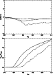 |
Figure 9:
Top: energy conservation as a function of expansion factor for run
P256L5 (solid line), P128L4 (dotted line) and P064L3 (dashed
line). Bottom: total number of cells in the AMR grid hierarchy
(including split cells) divided by the initial number of coarse cells
as a function of expansion factor for the same 3 runs. |
| Open with DEXTER |
A standard measure of the quality of a numerical simulation is to
check for total energy conservation errors. Since Euler equations are
solved in conservative form in RAMSES, the main source of energy
conservation errors comes from the gravitational source terms, for
both baryons and dark matter components. Figure 9
shows the total energy conservation (in the form of the Layzer-Irvine
conservation equation for an expanding universe) for the 3 AMR
runs. The maximum errors are found to be 2%, 1% and 0.5% for
P064L3, P128L4 and P256L5 respectively. The maximum error in the
energy conservation occurs when a significant number of refinements
are built for the first time, around
 ,
3 and 5 for
P064L3, P128L4 and P256L5 respectively.
,
3 and 5 for
P064L3, P128L4 and P256L5 respectively.
In Fig. 9 is also shown the total number of cells
in the AMR tree structure (including split cells), in units of the
number of coarse cells. It is worth noticing that this numbers should
have remained exactly equal to 1 for a strict Lagrangian mesh like the
ones described in Gnedin (1995) and Pen (1995). At the end of
the simulations, as clustering develops, the final number of mesh
points has increased by a factor of 2.5. This overhead is related to
the mesh smoothing operator (see Sect. 2.1.1). The mesh
evolution is therefore only "quasi'' Lagrangian.
![\begin{figure}
\par\includegraphics[width=15.3cm]{fig11.ps}\end{figure}](/articles/aa/full/2002/13/aa1593/Timg155.gif) |
Figure 10:
Gray scale images of the gas temperature (
T > 105 K), the gas
density (
 )
and the dark matter density ( )
and the dark matter density (
 )
in a planar cut through the computational volume
for run P256L5. The mesh structure within the plane is plotted in the
upper right panel (only octs boundaries are shown for
visibility). For sake of comparison, the density and temperature maps
obtained for run P256L0 (same initial conditions without refinements)
are shown in the 2 lower panels. )
in a planar cut through the computational volume
for run P256L5. The mesh structure within the plane is plotted in the
upper right panel (only octs boundaries are shown for
visibility). For sake of comparison, the density and temperature maps
obtained for run P256L0 (same initial conditions without refinements)
are shown in the 2 lower panels. |
| Open with DEXTER |
The adaptive mesh is dynamically modified at each time step during the
course of the simulation. Both hydrodynamics and N-body solvers take
advantage of the increased spatial resolution to improve the accuracy
of the solution in the refined regions.
Figure 10 illustrates this by comparing the gas and
dark matter density fields in a slice cutting through the
computational volume for run P256L5 (2563 particles with 5 levels
of refinements) with the density fields in the same slice for run
P256L0 (same initial conditions without refinements). Only overdense
cells are shown (
for baryons and
 for dark matter). One clearly sees that
both gas and dark matter density fields are much more dense and clumpy
when refinements are activated. On the other hand, it is reassuring to
see that both simulations agree with each other on large scale.
for dark matter). One clearly sees that
both gas and dark matter density fields are much more dense and clumpy
when refinements are activated. On the other hand, it is reassuring to
see that both simulations agree with each other on large scale.
The corresponding mesh structure is shown in the upper right part of
Fig. 10. The interest of using a tree-based
approach for defining the AMR hierarchy is striking: the grid
structure closely follows the geometry of the density field, from a
typical filamentary shape at large scale, to a more spherical and
compact shape in the higher density haloes cores. If one examines the
central filament connecting the 2 massive haloes in the images of
Fig. 10, one sees that it follows a typical
pancake-like structure, with 2 dark matter caustics on each side of a
gas filament. This structure, though interesting, is not dense enough
to be refined by our refinement strategy. We could have lowered the
density thresholds to trigger new refinements in this region, at the
price of an increased collisionality for dark matter. This would
result in a spurious fragmentation of the pancake structure
(Melott et al. 1997).
The temperature map (T > 105 K) in the same planar cut exhibits the
typical flower-like structure of strong cosmological accretion shocks
around large haloes. These strong shocks propagates exclusively in
large voids in between filaments that intersect each other at the
central halo position: this is due to the higher gas pressure within
the filaments that inhibits shock propagation in the direction aligned
with the filaments. This property of cosmological shock waves is of
great importance here, since it implies that strong shocks propagates
almost exclusively from high to low resolution regions of the grid. On
the other hand, weak shocks occurring during sub-halo mergers along
the filaments can enter high resolution regions of the mesh as
clustering develops. Since the oscillatory behavior outlined in
Sect. 3.5 disappears completely for weak shocks
(Berger & Collela 1989; Khokhlov 1998), we can conclude that cosmological shocks
propagation remains free from spurious effects associated to the
adaptive mesh structure.
4.5 The halo model
In order to analyze the results of the simulations in a more
quantitative way, I will use a powerful analytical theory: the so
called halo model. Several authors (Seljak 2000; Ma & Fry 2000; Scoccimarro et al. 2001; Cooray et al. 2000; Cooray 2001; Refregier & Teyssier 2001) have recently explored
the idea that both dark matter and baryons distributions can be
described by the sum of two contributions: (1) a collection of
virialized, hydrostatic haloes with overdensity  200 and described
by the Press & Schechter mass function and (2) a smooth background
with overdensity
200 and described
by the Press & Schechter mass function and (2) a smooth background
with overdensity  10 described by the linear theory of
gravitational clustering. The purpose of this paper is not to improve
upon earlier works on this halo model, but rather to use it as an
analyzing tool for our simulations. Therefore, the basic ingredients
of the halo model are only briefly recalled and will not be discussed
in great details. From now on, we consider only results obtained at
the final redshift z=0. The redshift evolution of the halo model is
discussed and compared to numerical simulations elsewhere
(Refregier et al. 2000; Refregier & Teyssier 2001).
10 described by the linear theory of
gravitational clustering. The purpose of this paper is not to improve
upon earlier works on this halo model, but rather to use it as an
analyzing tool for our simulations. Therefore, the basic ingredients
of the halo model are only briefly recalled and will not be discussed
in great details. From now on, we consider only results obtained at
the final redshift z=0. The redshift evolution of the halo model is
discussed and compared to numerical simulations elsewhere
(Refregier et al. 2000; Refregier & Teyssier 2001).
Haloes are defined as virialized clump of gas and dark matter, with
total mass defined as the Virial mass
 |
(40) |
where the Virial density contrast
 is related to the
Virial overdensity by
is related to the
Virial overdensity by
 .
For
.
For
 and z=0, one has
 (Eke et al. 1998). The dark matter follows the Navarro et al.
(NFW; Navarro et al. 1996) density profile
(Eke et al. 1998). The dark matter follows the Navarro et al.
(NFW; Navarro et al. 1996) density profile
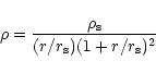 |
(41) |
whose parameters are connected to the halo Virial mass by
![\begin{displaymath}M_{\rm vir} = 4\pi \rho_{\rm s} r_{\rm s}^3 \left[ \ln (1+c) - \frac{c}{1+c}
\right]\cdot
\end{displaymath}](/articles/aa/full/2002/13/aa1593/img165.gif) |
(42) |
The only remaining free parameter (apart from
 )
is the so
called concentration parameter
)
is the so
called concentration parameter
 .
This parameter
exhibits a good correlation with halo mass in numerical simulations
that can be fitted analytically to match the numerical results
(Ma & Fry 2000). The final ingredient is to assume that the halo
distribution is described by the Press & Schechter mass function
(Press & Schechter 1974).
.
This parameter
exhibits a good correlation with halo mass in numerical simulations
that can be fitted analytically to match the numerical results
(Ma & Fry 2000). The final ingredient is to assume that the halo
distribution is described by the Press & Schechter mass function
(Press & Schechter 1974).
The total mass power spectrum can then computed as the sum of 2
components
P(k) = P1(k) +P2(k), where P1(k) is a non-linear
term corresponding to the mass correlation within halos, and P2(k)is a linear term corresponding to the mass correlation between 2
halos. Both terms have relatively straightforward analytical
expressions that are not recalled here (Seljak 2000; Ma & Fry 2000; Scoccimarro et al. 2001).
The gas distribution within halos is supposed to follow the isothermal
hydrostatic equilibrium. The temperature remains constant within the
halo Virial radius, and is taken equal to the halo Virial temperature
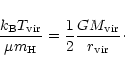 |
(43) |
Note that temperature profiles determined in numerical simulations are
neither isothermal nor equal to the Virial temperature. Therefore,
the halo model can only be considered as a crude approximation,
describing the gas distribution in a statistical sense only. Moreover,
the temperature profiles observed in large X-ray clusters is more or
less affected by cooling flows in the central regions. Including all
physical ingredients that might affect the thermal structure in the
core of virialized halos is beyond the scope of this paper. Only
adiabatic hydrodynamics is considered here.
Solving the hydrostatic equilibrium equation in the isothermal case
(using the NFW mass distribution) leads to the following gas density
profile (Suto et al. 1998)
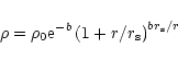 |
(44) |
where the dimensionless parameter b is given by
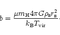 |
(45) |
The central density  is computed by specifying that the total
baryons mass within the Virial radius is equal to
is computed by specifying that the total
baryons mass within the Virial radius is equal to
 .
.
In the next section, the gas pressure power spectrum is computed from
RAMSES numerical simulations and compared to the halo model
predictions. The pressure power spectrum is quite an interesting
quantity in cosmology, since it is directly related to the
Sunyaev-Zeldovich induced Cosmic Microwave Background
anisotropies
angular power spectrum (Sunyaev & Zeldovich 1980; Rephaeli 1995). It can be computed within
the halo model framework using the same two terms as for the total
mass density power spectrum
P(k) = P1(k) +P2(k). Exact analytical
expressions can be found in Cooray (2001) and Refregier & Teyssier (2001).
![\begin{figure}
\par\includegraphics[width=15.5cm]{fig12.ps}\end{figure}](/articles/aa/full/2002/13/aa1593/Timg173.gif) |
Figure 11:
Dark matter density (left panels) and gas pressure (right panels)
power spectra for RAMSES runs with refinements (upper panels) and
without refinements (lower panels). In each plot, the solid line
corresponds to the halo model prediction, while the dotted line
(dashed and dot-dashed) corresponds to numerical results with 2563(1283 and 643) particles. Label "AMR'' stands for AMR runs
(P256L5, P128L4 and P64L3), while label "PM'' stands for runs without
refinement (P256L0, P128L0 and P64L0). For each power spectrum, the
curve ends at the Nyquist frequency corresponding to the formal
resolution of the simulation (
 in
Table 1).
in
Table 1). |
| Open with DEXTER |
In this section, both dark matter density and gas pressure power
spectra are computed and compared to the halo model predictions. In
order to study the convergence properties of the numerical solution,
results obtained with different mass and spatial resolutions are
examined.
Computing power spectra for simulations with such high dynamical range
requires to go beyond traditional methods based on regular Cartesian
meshes: recall that our highest resolution run has a formal resolution
of 81923. We use instead a multi-grid method based on a hierarchy of
nested cubic Cartesian grids (Jenkins et al. 1998; Kravtsov & Klypin 1999). Each
level of the hierarchy corresponds to the code AMR levels (from
to
)
and covers the whole computational
volume with  cubic grids of size nx3. At a given level,
a dark matter density field is computed for each grid using CIC
interpolation, and all grids are stacked together in a single,
co-added density field. This density field is then Fourier analyzed
using FFT technique. From the resulting power spectrum, only modes
spanning the range
cubic grids of size nx3. At a given level,
a dark matter density field is computed for each grid using CIC
interpolation, and all grids are stacked together in a single,
co-added density field. This density field is then Fourier analyzed
using FFT technique. From the resulting power spectrum, only modes
spanning the range
![$2^\ell \times \left[ k_{\rm min}, k_{\rm max}
\right]$](/articles/aa/full/2002/13/aa1593/img175.gif) are kept as reliable estimations of the true power spectrum,
with
are kept as reliable estimations of the true power spectrum,
with
 and
and
 .
The Nyquist frequency
.
The Nyquist frequency
 depends on the size
of the cubic grid, chosen here equal to the coarse grid size
nx3, so that
depends on the size
of the cubic grid, chosen here equal to the coarse grid size
nx3, so that
 .
At the 2 extreme
spatial scales, we have however
.
At the 2 extreme
spatial scales, we have however
 (for
)
and
(for
)
and
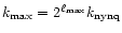 (for
). The maximum frequency considered in the
present analysis corresponds therefore to the formal Nyquist
frequency of each simulation
(for
). The maximum frequency considered in the
present analysis corresponds therefore to the formal Nyquist
frequency of each simulation
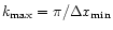 (see Table 1). The same procedure is applied to the
pressure field, except that CIC interpolation is no longer needed.
(see Table 1). The same procedure is applied to the
pressure field, except that CIC interpolation is no longer needed.
4.6.2 Results
The resulting power spectra are shown in Fig. 11
for the 3 runs with refinements (labeled "AMR'') and without
refinements (labeled "PM''). For comparison, the dark matter and
pressure power spectra predicted by the halo model are plotted as
solid lines.
The dark matter power spectrum shows a striking agreement with the
halo model prediction, down to the formal resolution limit. Note that
the halo model free parameters has been tuned in order to recover
simulations results (Ma & Fry 2000). Results obtained here are therefore
consistent with those obtained by other authors (Jenkins et al. 1998; Kravtsov & Klypin 1999), and can be considered as a powerful integrated test of
the code. For each mass resolution, the power spectrum is plotted up
to the formal Nyquist frequency. For AMR runs with refinements
activated, the numerical power spectrum is dominated at high wave
numbers by the Poisson noise due to particle discreteness effects (see
the small increase of power around
). We can conclude
that the numerical power spectrum has converged for each run, down to
the limit imposed by the finite mass resolution, without being
affected by the finite spatial resolution. For runs without
refinements, the limited dynamical range has a noticeable effect on
the resulting power spectrum at much larger scale: the spatial
resolution is therefore a strong limiting factor in this case.
Let us now examine the gas pressure power spectrum
(Fig. 11). The overall agreement of the numerical
results with the halo model predictions is relatively good: the
correct behavior is captured at all scales within a factor of 2 for
our highest resolution run (P256L5). Note that the halo model has no
free parameters for the gas distribution, as soon as the dark matter
parameters are held fixed. At large scale, the numerical power
spectrum appear to converge to the halo model predictions (run P128L4
and run P256L5 give exactly the same results). Note that a rather high
mass resolution is needed for this convergence to occur (>1283particles), as opposed to the dark matter density power spectrum for
which the correct large scale power is recovered even with 643particles. At intermediate scales (around 1 h Mpc-1), the halo
model predictions slightly underestimate the pressure power spectrum.
Since numerical results have also converged at these scales, this
discrepancy might be due to the fact that intermediate density regions
(
 )
are completely neglected in the halo model. These
regions are believed to be composed of warm filaments, whose pressure
obviously cannot be completely neglected.
)
are completely neglected in the halo model. These
regions are believed to be composed of warm filaments, whose pressure
obviously cannot be completely neglected.
At small scales, the situation remains quite unclear. On one hand, one
clearly sees in Fig. 11 that an increased
dynamical range has a dramatic effect on the resulting pressure power
spectra. The power is much higher on small scales for AMR runs than
for runs without refinements. On the other hand, for AMR runs, the
convergence of the numerical results to the "true'' solution is not
as fast as that of the dark matter power spectrum. Some hints of
convergence between run P128L4 and run P256L5 can be seen in
Fig. 11. Indeed, without refinements (runs P64L0,
P128L0 and P256L0), the cut off in the pressure power spectrum is
directly proportional to the spatial resolution of the simulation. The
same is true between runs P64L3 and P128L4, while for run P256L5, the
effect of spatial resolution appears to weaken slightly. More
interesting is the large discrepancy in slope at large k between the
halo model and the solution obtained by run P256L5. As discussed in
the next section, this is probably due to the assumption of
isothermality in the halo model, which is ruled out by simulation
results for individual halo temperature profiles.
![\begin{figure}
\par\includegraphics[width=18cm]{fig13.ps}\end{figure}](/articles/aa/full/2002/13/aa1593/Timg184.gif) |
Figure 12:
Color maps showing various projected quantities for the 5 most massive
halos extracted from run P256L5. The projected volume is in each case
a cube of 6.25 h-1 Mpc aside. The color coding is based on a
logarithmic scale for each plot. From top to bottom: 1- Projected dark
matter particle distribution (the color coding corresponds to the
local particle density). 2- X-ray emissivity map. 3- X-ray (emission
weighted) temperature map. 4- Sunyaev-Zeldovich decrement parameter
(equivalent to the integrated pressure along the line of sight). 5-
Projected adaptive mesh structure (only oct boundaries are shown). |
| Open with DEXTER |
![\begin{figure}
\par\includegraphics[width=17.2cm]{fig14.ps}\end{figure}](/articles/aa/full/2002/13/aa1593/Timg185.gif) |
Figure 13:
Radial profiles for the 5 most massive halos showing various
quantities averaged along radial bins. In each plot, the dotted line
(dashed and dot-dashed) comes from run P256L5 (P128L4 and P64L3). From
top to bottom: 1- Dark matter overdensity profile (the best-fit NFW
analytical profile is shown as a solid line). 2- Gas overdensity
profile (the corresponding "hydrostatic isothermal model'' analytical
profile is also shown as a solid line). 3- Mass averaged temperature
profile (the corresponding "hydrostatic beta model'' analytical
profile is also shown as a solid line). 4- Pressure profile (the
corresponding "hydrostatic isothermal model'' analytical profile is
also shown as a solid line). 5- Volume averaged refinement levels. |
| Open with DEXTER |
The internal structure of the 5 largest halos found in the highest
resolution run (P256L5) is now examined in great detail. It is worth
mentioning that this analysis is made possible thanks to the large
dynamical range obtained in our simulation (
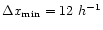 kpc), although it was not optimized to study individual halo
properties. The next step to go beyond what is presented here would be
to perform so called "zoom simulations'', with nested, higher
resolution, initial conditions particle grids centered on single halos
(Bryan & Norman 1997; Eke et al. 1998; Yoshida et al. 2000; Abel et al. 2000). The main advantage of the
present "brute force'' approach is to combine both large and small
scale results in the analysis. In order to study the convergence
properties of individual halo profiles, results obtained for runs
P256L5, P128L4 and P64L3 are compared. Recall that a direct
comparison of the same halo at different mass and spatial resolution
is possible, since the same initial conditions were used (and degraded
to the correct mass resolution) for each run. Runs without refinement
(P256L0, P128L0 and P64L0) are discarded from this analysis, because
they completely lack the necessary dynamical range to resolve the
internal structure of individual halos.
kpc), although it was not optimized to study individual halo
properties. The next step to go beyond what is presented here would be
to perform so called "zoom simulations'', with nested, higher
resolution, initial conditions particle grids centered on single halos
(Bryan & Norman 1997; Eke et al. 1998; Yoshida et al. 2000; Abel et al. 2000). The main advantage of the
present "brute force'' approach is to combine both large and small
scale results in the analysis. In order to study the convergence
properties of individual halo profiles, results obtained for runs
P256L5, P128L4 and P64L3 are compared. Recall that a direct
comparison of the same halo at different mass and spatial resolution
is possible, since the same initial conditions were used (and degraded
to the correct mass resolution) for each run. Runs without refinement
(P256L0, P128L0 and P64L0) are discarded from this analysis, because
they completely lack the necessary dynamical range to resolve the
internal structure of individual halos.
Table 2:
Global properties of the 5 largest halos extracted from the highest
resolution run P256L5.
|
|
Haloes were detected in the dark matter particles distribution at the
final output time (z=0) using the Spherical Overdensity algorithm
(Lacey & Cole 1993), with overdensity threshold
 .
Only the 5
most massive haloes of the resulting mass function are considered for
the present analysis. Their global properties are listed
in Table 2. For each halo, the center is defined as the
location of the maximum in the dark matter density field. For
regular, relaxed haloes, this definition also corresponds to the
maximum in the baryons density field, and to the halo center of mass.
This is however not the case for irregular, not yet relaxed haloes, for
which this definition of the halo center is less robust.
.
Only the 5
most massive haloes of the resulting mass function are considered for
the present analysis. Their global properties are listed
in Table 2. For each halo, the center is defined as the
location of the maximum in the dark matter density field. For
regular, relaxed haloes, this definition also corresponds to the
maximum in the baryons density field, and to the halo center of mass.
This is however not the case for irregular, not yet relaxed haloes, for
which this definition of the halo center is less robust.
Cubic regions 6.25 h-1 Mpc aside are then extracted around each
halo center. The resulting projected color maps for various relevant
quantities are shown in Fig. 12. Clusters 1 and 5
appear to be the most relaxed halos of our sample, while clusters 2, 3
and 4 show more substructures and irregularities within their Virial
radii. The adaptive mesh structure, also shown in
Fig. 12, closely matches the clumpy structure of
each halo. Note that the maximum level of refinement ( )
is
activated in the halo cores, where the formal spatial resolution
reaches 12 h-1 kpc (barely visible in Fig. 12).
The physical properties of these 5 haloes are now discussed
quantitatively.
)
is
activated in the halo cores, where the formal spatial resolution
reaches 12 h-1 kpc (barely visible in Fig. 12).
The physical properties of these 5 haloes are now discussed
quantitatively.
The projected dark matter particles distribution is shown in
Fig. 12, with a color coding corresponding to the
local particle overdensity. The dark matter distribution is far from
being smooth and spherically symmetric. It is however interesting to
compute the radial density profile and compare it to the NFW
analytical prediction. The result is shown in
Fig. 13, for our 3 different mass resolutions
(runs P256L5, P128L4 and P64L3). The density profile obtained in the
highest resolution run (P256L5) was fitted to the NFW profile, using
the concentration parameter c as fitting parameter. Best fit values
are listed in Table 2: they are fully consistent with
expected values for a CDM universe (Kravtsov et al. 1997; Eke et al. 1998).
The quality of the fit is impressive for clusters 1 and 5, which are
also the more relaxed haloes of our sample. The poorest fit was
obtained for cluster 4, with deviations as large as 50% at a radius
of 150 h-1 kpc. A close examination of the corresponding map in
Fig. 12 confirms that this halo is poorly relaxed in
its central region. By comparing the profiles obtained for different
mass resolution, one sees that the numerical profiles agree with each
other down to their resolution limit. This is in complete agreement
with our conclusion concerning the dark matter power spectrum:
simulated power spectra match closely the halo model prediction down
to their formal Nyquist frequency.
The baryons distribution within the selected haloes is similar on large
scales to the dark matter distribution. In Fig. 12,
simulated X-ray emission maps (using
 )
are good
tracers of the gas overdensity projected along the line of sight. One
can notice however that the hot gas is more smoothly distributed than
dark matter. This is even more striking in the central region of all
clusters, where the gas density reaches a plateau, reminiscent of a
)
are good
tracers of the gas overdensity projected along the line of sight. One
can notice however that the hot gas is more smoothly distributed than
dark matter. This is even more striking in the central region of all
clusters, where the gas density reaches a plateau, reminiscent of a
 model density profile. It is worth noticing that overdensities
(substructures) in the gas distribution usually appears as cold spots
in the X-ray (emission weighted) temperature map. On the other hand,
the cluster cores are significantly hotter than the surrounding gas in
most cases. We will come back to this point later.
model density profile. It is worth noticing that overdensities
(substructures) in the gas distribution usually appears as cold spots
in the X-ray (emission weighted) temperature map. On the other hand,
the cluster cores are significantly hotter than the surrounding gas in
most cases. We will come back to this point later.
Using the halo center as defined above, gas overdensity, mass weighted
temperature and pressure profiles were computed as a function of
radius and plotted in Fig. 13. For that
purpose, conserved variables such as mass and internal energy are
averaged into radial bins of increasing thickness, starting from the
formal resolution (12 h-1 kpc for run P256L5) up 3 times this
value at the Virial radius. The volume averaged refinement level is
also plotted in Fig. 13, giving some hints of
the effective spatial resolution as a function of radius. Based on the
results obtained during the Spherical Secondary Infall test presented
in Sect. 3.8, the actual resolution of the code
corresponds roughly to twice its formal resolution. For run P256L5
(P128L4 and P64L3), this gives a limiting radius of 24 (96 and 384) h-1 kpc,
above which numerical results are fully reliable.
Since dark matter density profile are well fitted for each halo by the
NFW analytical profile, the corresponding gas density profile can be
computed using Eq. (44). Recall that in the halo
model, the gas temperature is assumed to remain constant within the
Virial radius, and equal to the Virial temperature
(Eq. (43)). This is obviously not the case for our simulated
clusters (see Fig. 13), and explains why the halo
model profile is much more peaked in the central region than for
simulated profiles. For the pressure profiles, the situation is
however less dramatic, though still unsatisfactory. It is interesting
to notice that here again, the behavior of the pressure profiles is
fully consistent with previous results concerning the pressure power
spectrum: the isothermal halo model overestimates the pressure power
on small scales. This translates in to a much steeper slope at low
radii, as for the pressure power spectrum at large k. Moreover,
numerical results for the gas distribution within haloes have clearly
not converged yet, although the dependance of the computed profiles
with respect to the spatial resolution seems to weaken slightly
between run P128L4 and run P256L5, in exactly the same way as the
pressure power spectrum did in
Sect. 4.6.2. Conclusions are therefore similar: numerical
results show good evidence of converging at scales greater than 50 h-1 kpc.
Similar conclusions were obtained by Bryan & Norman (1997)
for a "zoom'' simulation of a single cluster. These authors obtained
very similar gas density and temperature profiles, with quite the same
convergence properties as the one obtained here. Consequently, the
isothermal halo model is likely to fail at scales less than 250 h-1 kpc.
As noted by several authors (Bryan & Norman 1997; Eke et al. 1998), the typical gas
density profile obtained in numerical simulations is much more
accurately described by the
model analytical solution
(Cavaliere & Fusco-Femiano 1976)
![\begin{displaymath}\rho = \rho_0 \left[ 1 + (r/r_{\rm core})^2 \right]
^{-3\beta_{\rm fit}/2}.
\end{displaymath}](/articles/aa/full/2002/13/aa1593/img192.gif) |
(46) |
Although the numerical results presented here have not fully converged
yet, it is worth exploring an alternative to the isothermal halo
model. The gas overdensity profile obtained in run P256L5 was thus
fitted with the
model formula, using both
 and
and
 as fitting parameters. Best fit values are listed
in Table 2 and are consistent with typical numbers
quoted by other authors (e.g. Eke et al. 1998). It is worth mentioning
that the quality of the fit is excellent in each case, except for
cluster 4, as expected from the previous analysis on the dark matter
distribution.
as fitting parameters. Best fit values are listed
in Table 2 and are consistent with typical numbers
quoted by other authors (e.g. Eke et al. 1998). It is worth mentioning
that the quality of the fit is excellent in each case, except for
cluster 4, as expected from the previous analysis on the dark matter
distribution.
Since both gas and dark matter density profiles are now determined to
a good accuracy, it is possible to perform a consistency check and
compute the temperature profile resulting from the assumption of
hydrostatic equilibrium. For that purpose, the analytical framework
developed by Varnieres & Arnaud (2001) is exactly what is needed here:
assuming a NFW profile for dark matter and a
model for
baryons, they derived analytically the corresponding hydrostatic
temperature profile. This temperature profile is shown for each
cluster in Fig. 13. The agreement with numerical
results is good: temperature rising towards the halo center is
therefore a direct consequence of hydrostatic equilibrium. After
closer examination, the small (20%) disagreement observed in clusters 2, 3 and 4 is due to the poorer fit of the NFW formula to the dark
matter simulated density profiles.
This non constant behavior of the halo temperature profile have been
already noticed by several authors in numerical simulations
(Bryan & Norman 1997; Eke et al. 1998; Loken et al. 2000) and also in X-ray observations of large
galaxy clusters (Markevitch et al. 1998). Note however that more physics
need to be included in current numerical simulations before performing
a reliable comparison to observations. On the other hand, the
idealized case of adiabatic gas dynamics is still of great theoretical
interest: one can hope to find a self-consistent description of the
gas distribution within haloes using such an approach. The main
ingredient to extend the halo model in this framework is to determine
the typical core radius (as well as
)
as a function
of halo mass and redshift. Eke et al. (1998) have already initiated this
challenging task using high resolution (zoom) SPH simulations for
large mass haloes (
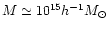 ), but more work
need to be done to probe a larger mass and redshift range. Using the
analytical formula of Varnieres & Arnaud (2001), it would be straightforward
to determine the corresponding temperature profile, and thus to
complete the description of the baryons component within this extended
halo model. This ambitious project will not be addressed here, but
will be considered in a near future.
), but more work
need to be done to probe a larger mass and redshift range. Using the
analytical formula of Varnieres & Arnaud (2001), it would be straightforward
to determine the corresponding temperature profile, and thus to
complete the description of the baryons component within this extended
halo model. This ambitious project will not be addressed here, but
will be considered in a near future.
5 Conclusions and future projects
A new N-body/hydrodynamical code, RAMSES, has been presented and
tested in various configurations. RAMSES has been written in
FORTRAN 90 and optimized on a vectorized hardware, namely the Fujitsu
VPP 5000 at CEA Grenoble. A parallel version was also impemented on
shared-memory systems using OpenMP directives. A distibuted memory
version of RAMSES is currently under construction using a domain
decomposition approach.
The main features of the RAMSES code are the followings:
1- the AMR grid is built on a tree structure, with new refinements
dynamically created (or destroyed) on a cell-by-cell basis. This
allows greater flexibility to match complicated flow geometries. This
property appears to be especially relevant to cosmological
simulations, since clumpy structures form and collapse everywhere
within the hierarchical clustering scenario;
2- the hydrodynamical solver is based on a second order Godunov
method, a modern shock capturing method that ensures exact total
energy conservation, as soon as gravity is not included.
Moreover, shock capturing relies on a Riemann solver, without any
artificial viscosity;
3- the refinement strategy that was retained for cosmological
simulations is based on a "quasi-Lagrangian'' mesh evolution. In this
way, the number of dark matter particles per cell remains roughly
constant, minimizing two-body relaxation and Poisson noise. On the
other hand, this refinement strategy is not optimal for baryons, since
one neglects to refine shock fronts (this would have been too costly
anyway). It has been carefully shown that in this case, as soon as
strong shocks propagate from high to low resolution regions of the
grid, no spurious effects appear.
The code has been tested in standard gas dynamical test cases (Sod's
test and Sedov's test), but also for integrated cosmological tests,
like Zel'dovich pancake collapse or Bertschinger spherical secondary
infall. It has been shown that the actual resolution limit of the
code is equal to roughly twice the cell size of the maximum refinement
level.
The RAMSES code has been finally used to study the formation of
structures in a low-density CDM universe. A careful
convergence analysis has been performed, using the same initial
conditions with various mass and spatial resolutions, for a fixed box
size
L=100 h-1 Mpc. The initial number of cell (at the coarse
level) was set equal to the initial particle grid (643, 1283 or
2563), for a final number of cells only 2.5 larger. The formal
spatial resolution in the largest run was 81923 or 12 h-1 kpc
comoving.
Numerical results have been compared to the analytical predictions of
the so called halo model, for both dark matter and gas pressure power
spectra, as well as individual haloes internal structure. A good
agreement was found between the halo model and the numerical results
for dark matter, down to the formal resolution limit. For the baryons
distribution, numerical results show some evidence of converging at
scales greater than 50 h-1 kpc for our highest resolution run.
The halo model reproduces simulations results only approximatively
(within a factor of 2) at these scales.
A simple extension of the halo model for the fluid component has been
proposed. The idea is to assume that the average gas density profile
within haloes is described by a
model, whose parameters still
need to be determined from first principles or from numerical
simulations and for a rather large mass range, which is far beyond the
scope of this paper (see however Eke et al. 1998). It is then possible
to deduce from hydrostatic equilibrium an analytical temperature
profile (Varnieres & Arnaud 2001) that accurately matches the simulation
results presented in this paper, and should therefore improve
considerably the halo model.
Extending the current work to "zoom'' simulations is currently under
investigation, using a set of nested grids as initial conditions, in
order to improve mass and spatial resolutions inside individual
haloes. This approach seems indeed very natural within the AMR
framework, and has already proven to be successful in recent attempts
(Bryan & Norman 1997; Abel et al. 2000). Future efforts in the RAMSES code development
will be however more focused on including more physics in the
description of the gaseous component, like cooling, star formation and
supernovae feedback.
Acknowledgements
The simulations presented in this paper were performed on the Fujitsu
VPP 5000 system of the Commissariat à l'Energie Atomique (Grenoble).
I would like to thank Philippe Kloos for his help on optimizing the
code. I would like to thank Remy Abgrall for inviting me to the
CEMRACS Summer School 2000 in Luminy (Marseille), where part of this
work was initiated. Special thanks to Alexandre Refregier who has
provided me with the software to compute analytical power spectra predicted
by the halo model, and to Stéphane Colombi who has provided me with the
software to compute numerical power spectra. I would like to thank
Jean-Michel Alimi, Edouard Audit, François Bouchet and Jean-Pierre
Chièze for enlightening discussions about the numerical methods
discussed in this paper. The author is grateful to an anonymous
referee, whose comments greatly improved the quality of the paper.
-
Abel, T., Bryan, G. L., & Norman, M. L. 2000,
ApJ, 540, 39
In the text
NASA ADS
-
Almgren, A. S., Bell, J. B., Colella, P., Howell, L. H., & Welcome,
M. L. 1998,
J. Chem. Phys., 142, 1
In the text
-
Barnes, J., & Hut, P. 1986,
Nature, 324, 446
In the text
NASA ADS
-
Berger, M. J., & Collela, P. 1989,
J. Chem. Phys., 82, 64
In the text
-
Berger, M. J., & Oliger, J. 1984,
J. Chem. Phys., 53, 484
In the text
-
Bertschinger, E. 1985,
ApJS, 58, 39
In the text
NASA ADS
-
Bouchet, F. R., & Hernquist, L. 1988,
ApJS, 68, 521
In the text
NASA ADS
-
Bryan, G. L., & Norman, M. L. 1997,
in ASP Conf. Ser. 123, Computational Astrophysics; 12th Kingston
Meeting on Theoretical Astrophysics, pp. 363-364
In the text
-
Cavaliere, A., & Fusco-Femiano, R. 1976,
A&A, 49, 137
In the text
NASA ADS
-
Cen, R. 1992,
ApJS, 78, 341
In the text
-
Chieze, J., Alimi, J., & Teyssier, R. 1998,
ApJ, 495, 630
In the text
-
Collela, P. 1990,
J. Chem. Phys., 87, 171
In the text
-
Collela, P., & Woodward, P. R. 1984,
J. Chem. Phys., 54, 174
In the text
-
Cooray, A. 2001,
Phys. Rev. D, in press [astro-ph/0005287]
In the text
-
Cooray, A., Hu, W., & Miralda-Escudé, J. 2000,
ApJ, 535, L9
In the text
NASA ADS
-
Couchman, H. M. P. 1991,
ApJ, 368, L23
In the text
NASA ADS
-
De Zeeuw, D. L. 1993,
Ph.D. Thesis, University of Michigan
In the text
-
Efstathiou, G., Davis, M., White, S. D. M., & Frenk, C. S. 1985,
ApJS, 57, 241
In the text
-
Eke, V. R., Navarro, J. F., & Frenk, C. S. 1998,
ApJ, 503, 569
In the text
NASA ADS
-
Evrard, A. E. 1988,
MNRAS, 235, 911
In the text
NASA ADS
-
Fryxell, B., Olson, K., Ricker, P., et al. 2000,
ApJS, 131, 273
In the text
-
Gingold, R. A., & Monaghan, J. J. 1977,
MNRAS, 181, 375
In the text
NASA ADS
-
Gnedin, N. Y. 1995,
ApJS, 97, 231
In the text
-
Gnedin, N. Y., & Bertschinger, E. 1996,
ApJ, 470, 115
In the text
NASA ADS
-
Hernquist, L., & Katz, N. 1989,
ApJS, 70, 419
In the text
-
Hockney, R. W., & Eastwood, J. W. 1981,
Computer Simulation Using Particles,
Computer Simulation Using Particles (New York: McGraw-Hill)
In the text
-
Jenkins, A., Frenk, C. S., Pearce, F. R., et al. 1998,
ApJ, 499, 20
In the text
NASA ADS
-
Jessop, C., Duncan, M., & Chau, W. Y. 1994,
J. Chem. Phys., 115, 339
In the text
-
Khokhlov, A. M. 1998,
J. Chem. Phys., 143, 519
In the text
-
Klypin, A. A., & Shandarin, S. F. 1983,
MNRAS, 204, 891
In the text
NASA ADS
-
Knebe, A., Kravtsov, A. V., Gottlöber, S., & Klypin, A. A. 2000,
MNRAS, 317, 630
In the text
NASA ADS
-
Kravtsov, A. V., & Klypin, A. A. 1999,
ApJ, 520, 437
In the text
NASA ADS
-
Kravtsov, A. V., Klypin, A. A., & Khokhlov, A. M. 1997,
ApJS, 111, 73
In the text
-
Lacey, C., & Cole, S. 1993,
MNRAS, 262, 627
In the text
NASA ADS
-
Loken, C., Norman, M., Nelson, E., et al. 2000,
in American Astronomical Society Meeting, 197, 10721
In the text
-
Ma, C. 1998,
ApJ, 508, L5
In the text
NASA ADS
-
Ma, C., & Fry, J. N. 2000,
ApJ, 543, 503
In the text
NASA ADS
-
Markevitch, M., Forman, W. R., Sarazin, C. L., & Vikhlinin, A. 1998,
ApJ, 503, 77
In the text
NASA ADS
-
Martel, H., & Shapiro, P. R. 1998,
MNRAS, 297, 467
In the text
NASA ADS
-
Melott, A. L., Shandarin, S. F., Splinter, R. J., & Suto, Y. 1997,
ApJ, 479, L79
In the text
NASA ADS
-
Navarro, J. F., Frenk, C. S., & White, S. D. M. 1996,
ApJ, 462, 563
In the text
NASA ADS
-
Pen, U. 1995,
ApJS, 100, 269
In the text
-
Press, W. H., & Schechter, P. 1974,
ApJ, 187, 425
In the text
NASA ADS
-
Press, W. H., Teukolsky, S. A., Vetterling, W. T., & Flannery, B. P.
1992,
Numerical recipes in FORTRAN. The art of scientific computing
(Cambridge: University Press), 2nd ed.
In the text
-
Refregier, A., Komatsu, E., Spergel, D. N., & Pen, U. L. 2000,
Phys. Rev. D, 61, 123001
In the text
-
Refregier, A., & Teyssier, R. 2001,
A&A, submitted [astro-ph/0012086]
In the text
-
Rephaeli, Y. 1995,
ARA&A, 33, 541
In the text
NASA ADS
-
Ryu, D., Ostriker, J. P., Kang, H., & Cen, R. 1993,
ApJ, 414, 1
In the text
NASA ADS
-
Saltzman, J. S. 1994,
J. Chem. Phys., 115, 153
In the text
-
Scoccimarro, R., Sheth, R. K., Hui, L., & Jain, B. 2001,
ApJ, 546, 20
In the text
NASA ADS
-
Sedov, L. I. 1993,
Similarity and Dimensional Methods in Mechanics
(Boca Raton: CRC Press), 10th ed.
In the text
-
Seljak, U. 2000,
MNRAS, 318, 203
In the text
NASA ADS
-
Sunyaev, R. A., & Zeldovich, I. B. 1980,
ARA&A, 18, 537
In the text
NASA ADS
-
Suto, Y., Sasaki, S., & Makino, N. 1998,
ApJ, 509, 544
In the text
NASA ADS
-
Teyssier, R., Chièze, J., & Alimi, J. 1998,
ApJ, 509, 62
In the text
NASA ADS
-
Toro, E. F. 1997,
Riemann Solvers and Numerical Methods for Fluid Dynamics
(Berlin: Springer)
In the text
-
Truelove, J. K., Klein, R. I., McKee, C. F., et al. 1998,
ApJ, 495, 821
In the text
NASA ADS
-
Varnieres, P., & Arnaud, M. 2001,
in preparation
In the text
-
White, M., & Bunn, E. F. 1995,
ApJ, 450, 477
In the text
NASA ADS
-
Yahagi, H., & Yoshii, Y. 2001,
ApJ, 558, 463
In the text
NASA ADS
-
Yoshida, N., Springel, V., White, S. D. M., & Tormen, G. 2000,
ApJ, 535, L103
In the text
NASA ADS
Copyright ESO 2002
![\begin{figure}
\par\includegraphics[width=16.6cm]{aa1593f1.ps}\end{figure}](/articles/aa/full/2002/13/aa1593/img90.gif)
![\begin{figure}
\par\includegraphics[width=16.6cm]{aa1593f2.ps}\end{figure}](/articles/aa/full/2002/13/aa1593/img95.gif)
![\begin{figure}
\par\includegraphics[width=16.1cm]{aa1593f3.ps}\end{figure}](/articles/aa/full/2002/13/aa1593/img100.gif)
![\begin{figure}
\par\includegraphics[width=16.2cm]{aa1593f4.ps}\end{figure}](/articles/aa/full/2002/13/aa1593/img110.gif)
![\begin{figure}
\par\includegraphics[width=12.6cm,clip]{aa1593f5.ps}\end{figure}](/articles/aa/full/2002/13/aa1593/img114.gif)
![\begin{figure}
\par\includegraphics[width=16.1cm]{aa1593f6.ps}\end{figure}](/articles/aa/full/2002/13/aa1593/img115.gif)
![\begin{figure}
\par\includegraphics[width=16.6cm]{aa1593f7.ps}\end{figure}](/articles/aa/full/2002/13/aa1593/img120.gif)
![\begin{figure}
\par\includegraphics[width=16.4cm]{aa1593f8.ps}\end{figure}](/articles/aa/full/2002/13/aa1593/img130.gif)
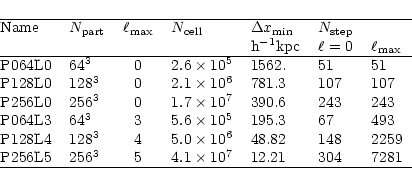
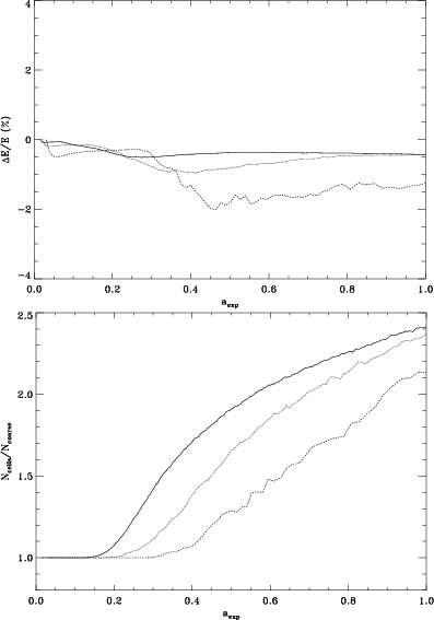
![\begin{figure}
\par\includegraphics[width=15.3cm]{fig11.ps}\end{figure}](/articles/aa/full/2002/13/aa1593/img155.gif)
![\begin{figure}
\par\includegraphics[width=15.5cm]{fig12.ps}\end{figure}](/articles/aa/full/2002/13/aa1593/img173.gif)
![\begin{figure}
\par\includegraphics[width=18cm]{fig13.ps}\end{figure}](/articles/aa/full/2002/13/aa1593/img184.gif)
![\begin{figure}
\par\includegraphics[width=17.2cm]{fig14.ps}\end{figure}](/articles/aa/full/2002/13/aa1593/img185.gif)