A&A 383, 296-301 (2002)
DOI: 10.1051/0004-6361:20011416
Q. Y. Peng1 - A. Vienne2 - K. X. Shen3
1 - Department of Computer Science, Jinan University, Guangzhou 510632, PR China
and
United Laboratory for Optical Astronomy, Chinese Academy of Sciences
2 -
Institut de mécanique céleste et de calcul des éphémérides, Observatoire
de Paris, UMR 8028 du CNRS and
Université de Lille, 59000 Lille, France
3 -
Shanxi Astronomical Observatory, Chinese Academy of Sciences, Lintong, Shanxi 710600, PR China and
Chinese National Astronomical Research Center
Received 25 July 2001 / Accepted 13 September 2001
Abstract
A positional measuring procedure for the eight major
satellites of Saturn (Mimas, Enceladus, Tethys, Dione, Rhea,
Titan, Hyperion and Iapetus) is developed. Using this procedure,
199 frames of CCD images, obtained with the 1-meter telescope at
the Yunnan Observatory from 1996-2000, are measured. These
positions are compared to the ones computed with the Vienne &
Duriez ephemerides (TASS1.7). The calibrated parameters of the CCD
scale and orientation are determined by the comparison of their
measurement coordinates with computed positions of four bright
satellites: Tethys, Dione, Rhea and Titan. A catalog of 913
differential positions has been obtained. Analysis of the data as
inter-satellite positions shows that these observations of the
above-mentioned four satellites have root-mean-square residuals of
0.04 arcsec in the sense of (O-C) (Observed minus Computed). The
positional measuring procedure is shown to be good enough to
obtain a small dispersion in the observations for the major
Saturnian satellites.
Key words: planets and satellites: individual: Saturn - techniques: image processing - astrometry
Astrometric observations of the eight major Saturnian satellites (S1-S8) have a long history of more than 100 years. Usually, traditional meridian observations, photographic observations, high precision mutual observations and CCD observations can be obtained. Nowadays, a CCD chip has been adopted as a regular receptor for many long-focus telescopes as a replacement for a photographic plate. Probably, CCD chips will be mainly used for a long time for the astrometry of the satellites. To refine their ephemerides to be compatible with the existing and planned spacecraft missions (CASSINI, for example), a large number of observations with high precision for the major saturnian satellites are continuously needed. Theoretical research on the Saturnian satellites has made a great progress. For instance, the theories of Taylor & Shen (1988), Dourneau (1993), Harper & Taylor (1993) and TASS 1.7 (Vienne & Duriez 1995; Duriez & Vienne 1997) have been developed in less than one decade. The internal precision for these theories are quite good. For example, TASS presents high precision of about ten kilometers (Vienne & Duriez 1995).
It is well known that, since the scattered light from Saturn and its rings can cause a strong gradient in the background level near its satellite, the center of its satellite is shifted towards the planet center. The shift is very significant and systematic in nature and needs to rectify to a flat background by subtracting the scattered light contributed by the planet and its rings.
Various techniques have been devised over the years for making this type of subtraction for other planets as well as Saturn. For example, an analytic subtraction of a planet and its scattered light was successfully adopted by Pascu et al. (1987) for Miranda. A similar method, which made a supposition of circular symmetry for the scattered light (see Eqs. (2) and (3) in Stone & Harris 2000), was developed for FASTT CCD observations at the USNO, Flagstaff. Another successful example was a planet-symmetry method devised by Veiga & Martins (1995) for Uranian satellites. Also, Colas & Arlot (1991) found the center of Phobos and Deimos from CCD observations, calculating the center of light after the subtraction of the background that is fitted by a polynomial surface. In addition, Beurle et al. (1993) calculated the center of each Saturnian satellite by using a centroid algorithm that chooses a small box in order to minimize the effects of gradients in the background close to the heavily over-exposed image of Saturn and its rings.
This paper presents an alternate positional measuring procedure, which is expected to remove the halo light of Saturn and its rings. Section 2 gives some specifications of the telescope and CCD chip for experimental observations. In Sect. 3, the procedure is described in detail. The following section includes the solution for calibration parameters for the CCD chip used. Section 4 deals with the calibrated positions. We present in Sect. 5 the comparison of the obtained positions with those deduced from the ephemerides. We also compare our results with some previous important ones and give a catalog of the corresponding astrometric data. Finally, concluding remarks are given in Sect. 6.
| Focal length | 1300 cm |
| F-Ratio | 13 |
| Diameter of Primary mirror | 100 cm |
| CCD field of view | 6
|
| Size of pixel | 24 |
| Size of CCD array | 1024 |
| Angular extent per pixel | 0
|
During the years 1996-2000, 5 nights of observations with 199 frames of CCD
images in total were obtained with the 1-meter telescope at the Yunnan observatory
(Longitude E102 47
![]() 3, Latitude N25 1
3, Latitude N25 1
![]() 5 and Height
2000 m above sea level). In Table 1, some specifications for
the telescope and CCD chip are given.
5 and Height
2000 m above sea level). In Table 1, some specifications for
the telescope and CCD chip are given.
| Subset | Date | Filter | Exp-time (s) | Mimas | Enceladus | Tethys | Dione | Rhea | Titan | Hyperion | Iapetus |
| 1996 | 10/30 | I | 5-10 | 54 | 54 | 0 | 54 | 54 | 0 | 0 | 54 |
| 1997 | 10/10 | I | 1-5 | 0 | 24 | 24 | 24 | 24 | 24 | 0 | 0 |
| 1999 | 12/1 12/2 | B | 5-10 | 0 | 49 | 49 | 49 | 49 | 49 | 49 | 0 |
| 2000 | 11/17 | I | 5-8 | 0 | 34 | 72 | 34 | 72 | 72 | 72 | 72 |
| total | 54 | 161 | 145 | 161 | 199 | 145 | 121 | 126 |
For experimental observations, Johnson I-type and B-type filters were used. The use of the B-type filter was originally devised to decrease the brightness for both the primary planet and its satellites and to increase the exposure time so that the relative positions between satellites have quite good precision. We will see in Sect. 5.1 that the design is not profitable. Table 2 gives the raw measurement statistics for the number of pairs of pixel coordinates (x,y) of each satellite, observational dates, filter used and exposure time.
Unfortunately, Titan did not appeared in the CCD field of view for the data subset of 1996 due to the lack of experience.
![\begin{figure}
\par\includegraphics[width=7.8cm,clip]{fig1.eps}
\end{figure}](/articles/aa/full/2002/07/aa1731/img6.gif) |
Figure 1: A CCD image for Saturn and its rings is displayed after its brightness and contrast are adjusted. The observation date for this image is Nov. 17, 2000. |
| Open with DEXTER | |
In order to obtain raw pixel coordinates for some Saturnian satellites in the proximity of the planet and its rings (usually, Mimas, Enceladus, Tethys, Dione and Rhea), the following steps are adopted.
Step 1: by adjusting image brightness and contrast, we can see Saturn and its rings or parts of its rings (see Fig. 1). The pixel coordinates of two terminal points for the rings' maximum axis can be measured visually by a + type cursor. Therefore, the equations for the maximum axis and the minimum axis of the Saturnian ring image can be solved easily.
Step 2: suppose that the count distribution I(i,j) in the
pixel coordinates (i,j) on an image is symmetric relative to
the ring maximum axis or/and minimum axis. Then, the halo light in
the area of a measured satellite is thought to be removed by a
simple abstraction of its count distribution by its symmetric area
(Fig. 2). The symmetric area may be chosen relative
to the ring maximum or minimum axis, depending on which area is
nearer to the measured satellite. The reason is that the
above-mentioned supposition is thought to be satisfied better in
this manner.
![\begin{figure}
\includegraphics[width=7.8cm,clip]{fig2.eps}
\end{figure}](/articles/aa/full/2002/07/aa1731/img7.gif) |
Figure 2: The image in Fig. 1 is displayed once again after the removal of halo light. In the image, a very faint satellite, Enceladus, can be seen in the bottom rectangle enclosing it. The upper left rectangle of Enceladus is used for the determination of the satellites' mean background and its rms error. |
| Open with DEXTER | |
Step 3: determination of the satellite center. Theoretically, several centering
algorithms for a star image can be used to determine the satellite center after
the above two steps. However, a satellite, especially one close to Saturn and
its rings is still located on an uneven background. Moreover, the planetary
motion during the observation can elongate the satellites image. According to
Stone (1989), a modified moment, method which suppressed the sky background
through a process of image thresholding is a very good routine for dealing with
high sky background levels. The method offers a significant gain in accuracy,
particularly for weak images over the traditional treatment of the moment (Auer
& van Altena 1978). Specifically, once the background level bis determined in the I(x,y) data array, each pixel in the array is thresholded
according to the following precepts:
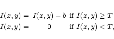
Now, a further modified version of the moment is developed in which Treplaces the b in the first precept. Experiment tests with actual observations
(Ji & Wang 1996; Peng & Mao 1998) have shown that the new
version of the moment method is even better, especially for weak stars or natural
satellites. For Saturnian satellites, another slight modification is made to
the threshold T. For Mimas, Enceladus and Hyperion,
![]() or even
or even
![]() is used depending on the signal-noise-ratio of the
measured satellites. During our image processing, the moment method for a measured
satellite center chooses a small rectangle, and the mean background band its rms (root-mean-square) error
is used depending on the signal-noise-ratio of the
measured satellites. During our image processing, the moment method for a measured
satellite center chooses a small rectangle, and the mean background band its rms (root-mean-square) error ![]() are determined with another
small rectangle near the satellite. The sizes of the two small rectangles can
be conveniently adjusted. Usually, we keep them approximately equal (see Fig. 2). Last, for the satellites Titan, Hyperion and Iapetus, Step 1 and Step 2 are usually neglected.
are determined with another
small rectangle near the satellite. The sizes of the two small rectangles can
be conveniently adjusted. Usually, we keep them approximately equal (see Fig. 2). Last, for the satellites Titan, Hyperion and Iapetus, Step 1 and Step 2 are usually neglected.
Most often, there is no good reference star on the frames which would allow us to do a complete astrometric reduction. So, we use an astrometric reduction for the case of inter-satellite measurements. The detailed description of this reduction can be seen in Vienne et al. (2001b). One can see also Vienne et al. (2001a) in which the reduction has been applied.
The frames registered and measured in pixels are comparable with ephemeris after taking into account some local effects: the atmospheric refraction, the stellar aberration, the central projection (projection of the celestial sphere on the tangential plane of the focal point), the light traveling time between the satellites and the diurnal parallax. These differential astrometric corrections done here were not automatically taken into account in previous works (see Vienne et al. 2001a).
We use TASS1.7 (Vienne & Duriez 1995; Duriez & Vienne 1997) for the saturnicentric positions of the satellites. According to Shen et al. (2001), TASS is now the best contemporary dynamical theory for Saturnian satellites and it is suggested to use TASS alone in the CCD reduction. We use the four satellites Tethys, Dione, Rhea and Titan to calibrate the scale and orientation of the CCD chip in each data subset. As we stated before, Titan was not observed in the 1996 data subset and only Dione and Rhea were used for the calibration. The positions of Saturn are given by the ephemerides SLP96 from the "Institut de mécanique céleste (IMCCE)'' (available at ftp://ftp.bdl.fr/pub/ephem/sun/slp96/) based on the VSOP87 planetary theory (Bretagnon & Francou 1988).
At a given date corrected for the light-travel time between the satellites,
we compute the apparent coordinates, ![]() and
and ![]() ,
of the satellites.
We use the corresponding positions
,
of the satellites.
We use the corresponding positions
![]() given in pixels from
the observed frame. So, with the relation
given in pixels from
the observed frame. So, with the relation
![]() ,
we compute an estimation
,
we compute an estimation
![]() of a and
b by a least square procedure. We deduce the scale factor
of a and
b by a least square procedure. We deduce the scale factor
![]() and the orientation of the receptor (the angle from the
and the orientation of the receptor (the angle from the ![]() -axis of
the camera to the true equator)
-axis of
the camera to the true equator)
![]() .
This procedure is applied for a set of frames. A series of frames can cover
several nights. So, we suppose that the receptor has been mounted in the same
way for all frames of the series. Table 3 gives the solved scale
and orientation for each data subset.
.
This procedure is applied for a set of frames. A series of frames can cover
several nights. So, we suppose that the receptor has been mounted in the same
way for all frames of the series. Table 3 gives the solved scale
and orientation for each data subset.
| Subset | ||
| (arcsec/pixel) | (radian) | |
| 1996 |
|
-3.12607864 |
| 1997 |
|
-3.10915524 |
| 1999 |
|
+3.12735097 |
| 2000 |
|
+3.10169865 |
The astrometric positions
![]() we have obtained are given in the J2000 system and all significant astrometric
corrections have been done. But, for a given series, they are given apart from
a scale factor and from a rotation. One can find in Vienne et al. (2001b)
more details and a discussion of the method for the case of inter-satellites
measurements. For example, as it is explained there, if we want to compute the
astrometric coordinates in any other way (e.g.: with other ephemerides), we have
only to touch up
we have obtained are given in the J2000 system and all significant astrometric
corrections have been done. But, for a given series, they are given apart from
a scale factor and from a rotation. One can find in Vienne et al. (2001b)
more details and a discussion of the method for the case of inter-satellites
measurements. For example, as it is explained there, if we want to compute the
astrometric coordinates in any other way (e.g.: with other ephemerides), we have
only to touch up ![]() and
and ![]() .
.
| 1996 |
|
|
|||
| satellites | N | means | rms | means | rms |
| S1-Mimas | 54 | -21 | 58 | -16 | 47 |
| S2-Enceladus | 54 | -6 | 24 | -45 | 51 |
| S4-Dione | 54 | +0 | 20 | +0 | 17 |
| S8-Iapetus | 54 | -150 | 150 | -81 | 83 |
| 1997 |
|
|
|||
| satellites | N | means | rms | means | rms |
| S2-Enceladus | 24 | +1 | 92 | +20 | 90 |
| S3-Tethys | 24 | +4 | 42 | -2 | 42 |
| S4-Dione | 24 | -10 | 65 | -4 | 68 |
| S5-Rhea | 24 | +8 | 86 | +5 | 81 |
| S3 S4 S5 S6 | 72 | +1 | 67 | +0 | 66 |
| 1999 |
|
|
|||
| satellites | N | means | rms | means | rms |
| S2-Enceladus | 49 | +9 | 46 | -11 | 49 |
| S3-Tethys | 49 | +9 | 37 | +0 | 53 |
| S4-Dione | 49 | +6 | 34 | -1 | 36 |
| S5-Rhea | 49 | -19 | 38 | -5 | 45 |
| S7-Hyperion | 49 | -38 | 92 | +104 | 138 |
| S3 S4 S5 S6 | 147 | -1 | 36 | -2 | 45 |
| 2000 |
|
|
|||
| satellites | N | means | rms | means | rms |
| S2-Enceladus | 34 | -57 | 62 | +12 | 42 |
| S3-Tethys | 72 | -5 | 23 | -5 | 29 |
| S4-Dione | 34 | -34 | 37 | -5 | 25 |
| S5-Rhea | 72 | +26 | 31 | +1 | 20 |
| S7-Hyperion | 72 | +2 | 22 | -26 | 43 |
| S8-Iapetus | 72 | -8 | 23 | -20 | 39 |
| S3 S4 S5 S6 | 178 | +2 | 29 | -3 | 25 |
Table 4 gives the mean residuals (O-C) (Observed minus Computed)
and rms (root-mean-square) errors for each satellite with respect to Titan or
Rhea (only for 1996 subset).
| N | mean | rms | mean | rms | |
|
|
|
||||
| S1 to S8 | 913 | 58 | 56 | ||
| S3 S4 S5 S6 | 451 | 39 | 40 | ||
Table 5 gives the statistics of all eight satellites relative
to Rhea or Titan and Table 6 gives the comparison of this work with some previous
important photographic data or the latest CCD observations.
| data set |
|
|
||||
| N | mean | rms | N | mean | rms | |
| AOC28 | 192 | -40 | 90 | 192 | +10 | 70 |
| A29 | 108 | -30 | 90 | 109 | +0 | 60 |
| VD92 | 434 | -7 | 130 | 434 | +12 | 100 |
| H+97 | 891 | -7 | 70 | 891 | +1 | 90 |
| Q+99, | 381 | 80 | 381 | 90 | ||
| this work | 451 | +1 | 40 | 451 | -2 | 40 |
Tables 5 and 6 show that our residual dispersion between the inter- satellites of Tethys, Dione, Rhea and Titan is quite small in comparisons to the best photographic or the latest CCD observations. Poor tracking probably causes the slightly bigger rms error in the 1997 data subset (Table 4). Even so, no obvious systematic difference is found in the mean residuals. It shows that our positional measuring procedure would be good to deal with the situation. By comparing Table 2 with Table 4, when I-type and B-type filters are used, no obvious systematic difference is found, either.
| opp | year | m | day (utc) | tt-utc | obs. | ref. | t | obj. | fl | obs1 | obs2 | s | f | O-C1 | O-C2 | r | - | s | xpix | ypix |
| s | arcsec (degree for C*) | arcsec | pixel | |||||||||||||||||
| 119 | 1996 | 10 | 30.5749132 | 62.184 | 286 | 302 | 1 | 15 | 11 | -46.9204156 | 5.9172545 | 2 | 1 | -0.118 | 0.049 | 5 | 0 | 1 | 125.874 | -13.889 |
| 119 | 1996 | 10 | 30.5749132 | 62.184 | 286 | 302 | 1 | 25 | 11 | -110.7493305 | 10.4010887 | 2 | 1 | -0.009 | -0.011 | 5 | 0 | 1 | 296.961 | -23.235 |
| 119 | 1996 | 10 | 30.5749132 | 62.184 | 286 | 302 | 1 | 45 | 11 | -132.9961025 | 12.0523440 | 2 | 1 | -0.015 | 0.021 | 5 | 0 | 1 | 356.595 | -26.729 |
| 119 | 1996 | 10 | 30.5749132 | 62.184 | 286 | 302 | 1 | 85 | 11 | -45.2907571 | -73.3128335 | 2 | 1 | -0.178 | -0.047 | 5 | 0 | 1 | 18.229 | 198.165 |
| 119 | 1996 | 10 | 30.5749132 | 62.184 | 286 | 302 | 1 | C5 | 11 | 165.2981011 | 156.5448468 | 2 | 1 | 999.999 | 999.999 | 5 | 0 | 1 | -436.203 | -426.105 |
| 119 | 1996 | 10 | 30.5749132 | 62.184 | 286 | 302 | 0 | C* | 11 | 2.5913720 | -1.6771020 | 2 | 1 | 999.999 | 999.999 | 5 | 0 | 1 | 99999.999 | 99999.999 |
| 119 | 1996 | 10 | 30.5791782 | 62.184 | 286 | 302 | 1 | 15 | 11 | -46.6083017 | 5.8987671 | 2 | 1 | 0.065 | 0.005 | 5 | 0 | 1 | 125.038 | -13.853 |
| ... | ||||||||||||||||||||
| 123 | 2000 | 11 | 17.7913715 | 64.184 | 286 | 302 | 0 | C* | 11 | 55.9767122 | 17.4245495 | 2 | 1 | 999.999 | 999.999 | 6 | 0 | 4 | 99999.999 | 99999.999 |
| 123 | 2000 | 11 | 17.7926910 | 64.184 | 286 | 302 | 1 | 86 | 11 | -144.3442720 | 102.5517423 | 2 | 1 | 0.004 | -0.038 | 6 | 0 | 4 | 374.639 | -289.620 |
| 123 | 2000 | 11 | 17.7926910 | 64.184 | 286 | 302 | 1 | 76 | 11 | 26.3411600 | -128.1610231 | 2 | 1 | -0.011 | -0.026 | 6 | 0 | 4 | -56.637 | 345.324 |
| 123 | 2000 | 11 | 17.7926910 | 64.184 | 286 | 302 | 1 | 36 | 11 | -184.5224289 | -78.6382809 | 2 | 1 | -0.001 | -0.053 | 6 | 0 | 4 | 501.580 | 190.230 |
| 123 | 2000 | 11 | 17.7926910 | 64.184 | 286 | 302 | 1 | 56 | 11 | -134.3295440 | -26.6458330 | 2 | 1 | 0.048 | -0.035 | 6 | 0 | 4 | 361.828 | 56.721 |
| 123 | 2000 | 11 | 17.7926910 | 64.184 | 286 | 302 | 1 | 26 | 11 | -119.7285179 | -69.6868116 | 2 | 1 | -0.011 | -0.026 | 6 | 0 | 4 | 327.454 | 173.319 |
| 123 | 2000 | 11 | 17.7926910 | 64.184 | 286 | 302 | 1 | 46 | 11 | -125.4039624 | -84.4916109 | 2 | 1 | -0.023 | -0.034 | 6 | 0 | 4 | 344.219 | 212.269 |
| 123 | 2000 | 11 | 17.7926910 | 64.184 | 286 | 302 | 1 | C6 | 11 | 117.9793628 | 131.0317168 | 2 | 1 | 999.999 | 999.999 | 6 | 0 | 4 | -329.373 | -337.667 |
| 123 | 2000 | 11 | 17.7926910 | 64.184 | 286 | 302 | 0 | C* | 11 | 55.9763859 | 17.4246366 | 2 | 1 | 999.999 | 999.999 | 6 | 0 | 4 | 99999.999 | 99999.999 |
Using ![]() and
and ![]() determined in Table 3,
and applying once more, but inversely, the local deformations, we get the coordinates
determined in Table 3,
and applying once more, but inversely, the local deformations, we get the coordinates
![]() of each measured object. The coordinates
of each measured object. The coordinates
![]() are astrometric, but there is an absolute part
are astrometric, but there is an absolute part
![]() and
and
![]() which does not come from the observations. C is defined so the frame
is the tangential plane of the celestial sphere at C. In order to not
interpret the observations as absolute ones, we give them in inter-satellite
form. That is
which does not come from the observations. C is defined so the frame
is the tangential plane of the celestial sphere at C. In order to not
interpret the observations as absolute ones, we give them in inter-satellite
form. That is
![]() and
and
![]() .
The index
.
The index ![]() is for the satellite object, and the index
is for the satellite object, and the index ![]() for the reference satellite. The catalog contains astrometric coordinates, in
the J2000 system, of the observations. All raw pixel coordinates are also included
in it. The dates correspond to the mid-time of the exposure. This date is not
light-time corrected. Table 7 gives an extract from the
first and last parts of the catalog of the 913 Saturnian satellites' differential
positions for all observed satellites. The format of the catalog is the same
as (Vienne et al. 2001a), and it is similar to that of Strugnell &
Taylor (1990). The full catalog is available on request at the CDS via
anonymous ftp to cdsarc.u-strasbg.fr (130.79.128.5). In FORTRAN code, one line
is read with the format:
for the reference satellite. The catalog contains astrometric coordinates, in
the J2000 system, of the observations. All raw pixel coordinates are also included
in it. The dates correspond to the mid-time of the exposure. This date is not
light-time corrected. Table 7 gives an extract from the
first and last parts of the catalog of the 913 Saturnian satellites' differential
positions for all observed satellites. The format of the catalog is the same
as (Vienne et al. 2001a), and it is similar to that of Strugnell &
Taylor (1990). The full catalog is available on request at the CDS via
anonymous ftp to cdsarc.u-strasbg.fr (130.79.128.5). In FORTRAN code, one line
is read with the format:
(i3,i5,i3,f11.7,f7.3,2i4,i2,1x,a2,a1,i2,i1,
2(1x,f13.7),2i2,2(1x,f7.3),3i3,2f10.3).
Here is a rapid description of the content of each record:
A positional measuring procedure is developed with the main aim of removing the halo light effect from Saturn and its rings on the background of its near satellites. In the procedure, a modified moment method for centering algorithm for Saturnian satellites is used. When the procedure is applied to 199 frames of CCD observational images obtained with the 1-meter telescope at the Yunnan Observatory during the years 1996-2000, 913 pairs of inter-satellites observations were obtained. The root-mean-square residual for four satellites of Tethys, Dione, Rhea and Titan is 0.04 arcsec after analysis of the data. It is proved that the procedure is good enough to obtain high accuracy observations for Saturnian satellites. Besides, no obvious difference between the two residuals from the I type filter and the B-type filter is found. Even so, the use of B-type filter is not profitable. We will use a I-type filter in future observations.
Acknowledgements
The first author would like to acknowledge Prof P. S. Chen, Prof W. Y. Zhang and their staff at the Yunnan Astronomical Observatory for giving us financial support and care during the observing run. this work was carried out with financial support partly from the College of Information Science and Technology, Jinan University.